Article

Compressive Sound Speed Profile Inversion Using Beamforming Results

1
Department of Defense System Engineering, Sejong University, Seoul 05006, Korea
2
Department of Naval Architecture and Ocean Engineering and Research Institute of Marine System Engineering, Seoul National University, Seoul 08826, Korea
*
Author to whom correspondence should be addressed.
Remote Sens. 2018, 10(5), 704; https://doi.org/10.3390/rs10050704
Submission received: 9 April 2018 / Revised: 24 April 2018 / Accepted: 2 May 2018 / Published: 4 May 2018
(This article belongs to the Special Issue Advances in Undersea Remote Sensing)

Abstract

:
Sound speed profile (SSP) significantly affects acoustic propagation in the ocean. In this work, the SSP is inverted using compressive sensing (CS) combined with beamforming to indicate the direction of arrivals (DOAs). The travel times and the positions of the arrivals can be approximately linearized using their Taylor expansion with the shape function coefficients that parameterize the SSP. The linear relation between the travel times/positions and the shape function coefficients enables CS to reconstruct the SSP. The conventional objective function in CS is modified to simultaneously exploit the information from the travel times and positions. The SSP is estimated using CS with beamforming of ray arrivals in the SWellEx-96 experimental environment, and the performance is evaluated using the correlation coefficient and mean squared error (MSE) between the true and recovered SSPs, respectively. Five hundred synthetic SSPs were generated by randomly choosing the SSP dictionary components, and more than 80 percent of all the cases have correlation coefficients over 0.7 and MSE along depth is insignificant except near the sea surface, which shows the validity of the proposed method.

Graphical Abstract

1. Introduction

It is crucial to estimate the sound speed profile (SSP) of a water column to reliably locate a source or to conduct geoacoustic inversion [1,2,3,4,5]. Many studies have used acoustic measurement data to infer the SSP (i.e., acoustic tomography) [6,7,8,9,10]. Originally, ocean acoustic tomography is conducted using travel times of arrivals measured at a single hydrophone [6]. Its application is limited by ocean noises that mask the arrivals. To mitigate the problem, multiple measurement at sensors in array is used with matched field inversion (MFI) [8,9]. In the SSP inversion process, replicas (synthetic acoustic data at the sensors of array) are generated according to the SSPs using underwater acoustic propagation model [11], and an objective function is defined to evaluate the similarity between the measured data and the replicas. The replicas corresponding to the maximum (or minimum) value from the objective function should then resemble the SSP from the ocean. In general, a genetic algorithm or simulated annealing is applied to solve the optimization problem [2,3]. It estimates the SSP more robustly at the cost of computational burden resulting from iterative use of propagation model. However, its performance relies on the propagation model and it cannot be applied to environments, where the propagation model is restricted owing to complexities of the ocean including geoacoustic parameters (sound speed, density, and attenuation) of sediment. This work suggests a novel inversion scheme for SSP, which employs compressive sensing (CS) with beamforming results (i.e., direction of arrivals (DOAs)). It inverts the SSP with enhanced signal-to-noise ratio (SNR) due to the beamforming and without intensive use of propagation model as well as geoacoustic parameters.
CS is a method that can solve an underdetermined linear system ( y = A x ) by using a sparsity promoting objective function [12,13]. y is a measurement vector, and x is an unknown vector that is to be recovered. A is a sensing matrix that shows the linear relation between x and y , and these are defined differently according to the given problem. In underwater acoustics, CS has been applied to obtain a high-resolution DOA with a limited number of sensors in an array [14,15,16,17,18], and the applicability of CS has been expanded to source localization [19,20] and ocean parameter inversion [10,21,22].
Recently, CS has been applied to obtain the SSP represented as a linear combination of shape functions in the SSP dictionary, with a sparsity-promoting objective function used to exploit the sparsity of the solution after constructing a linear relation between the (given) measurement and (unknown) parameter [10]. The measurement and the parameter to be recovered in the compressive SSP estimation are the acoustic fields at the sensors of a vertical line array (VLA) and the shape function coefficients, respectively. The acoustic fields are approximately linearized in terms of the shape function coefficients parameterizing the SSP. The SSP is reconstructed using the compressive SSP estimation that replicates the acoustic pressures at the sensors. During the process of replicating the pressures, information of geoacoustic parameters is needed.
In this work, beamforming results from the array are used with CS to infer the SSP. Practically, the DOAs are estimated with various beamforming schemes [11,14,15,16,17,18]. Here, the DOAs are calculated with eigenrays from a ray model. For convenience, a numerical experiment showing the DOAs matching the arrival angles of the eigenrays is illustrated. While the SSP is represented as a linear combination of the shape functions (e.g., empirical orthogonal functions (EOFs)) in the SSP dictionary [1,2,4,8,10,23], the travel time and position are linearized at a specific DOA using their Taylor expansion with the shape function coefficients, respectively. Thus, the proposed method eliminates the need for geoacoustic parameter information. The scheme on the inversion of SSP with the given beamforming results is delineated as follows. Section 2 introduces the detailed process for compressive SSP inversion using the beamforming results. A conventional objective function in CS is modified to simultaneously exploit the information from the position and travel time. Numerical experiments are conducted in the SWellEx-96 environment to examine the performance of the compressive SSP inversion. Finally, Section 4 summarizes this work.

2. Compressive SSP Inversion

This work adopts CS to recover the fine-scale structure of the SSP since the CS demonstrates a good performance for the SSP inversion with a limited number of observations [10]. However, instead of using acoustic fields that require geoacoustic parameters, the beamforming results from the VLA are used. The DOAs can be obtained using frequency-domain beamforming with the VLA, and the travel times (or relative delay times) of the arrivals can be acquired according to the DOAs using time-domain beamforming. The information for the arrivals regarding the travel times and positions is highly dependent on the SSP, and it is used in the current compressive SSP estimation.

2.1. Formulation of the Compressive SSP Inversion

SSP is represented using a linear combination of the shape functions in the SSP dictionary as below [10,23]:
c ( x ) = c 0 + Q x ,
where c ( x ) R K and c 0 R K are ocean and reference SSPs, respectively, that are evenly captured at K points along the depth. In this work, the source is located near the array (in the numerical experiment of Section 3, and they are apart by a horizontal range of 2 km), and variations of SSPs along the range are neglected. Q R K × N is an SSP dictionary composed of N unique shape functions ( q 1 , , N R K ) and x R N is a set of coefficients that correspond to the N shape functions. The shape functions are defined to express SSP with their linear combination, which enable SSP to be parameterized with the coefficients corresponding to the shape functions. The SSP dictionary is a matrix holding the shape functions as its columns. Recently, a dictionary learning in the form of unsupervised machine learning is applied to obtain the shape functions with SSP data, which are beneficial for CS by representing the SSP sparsely [23]. However, in this work, synthetic EOFs as Gaussian functions and conventional EOFs from principle component analysis are separately used as the N shape functions as those in Bianco and Gerstoft [10].
The travel time and arrival position of a ray are highly dependent on x (or SSP), and rays with the same arrival angles show distinct trajectories for different x . Figure 1 shows ray trajectories for the ocean SSP (dotted line) and reference SSP (solid line). Consider a ray that emanates from the source to the receiver for the ocean SSP. However, the backpropagated ray from the receiver using the reference SSP deviates from the source position in both the vertical and horizontal directions (Figure 1b,c). When overall SSP differences are small, the ocean SSP can be approximated by the reference SSP using Taylor expansion based on shape function coefficients. The depth and travel time for the ocean SSP at the source range can be denoted as follows:
D ( x ; θ j ) = D ( 0 ; θ j ) + i = 1 N D ( x ; θ j ) x i | x = 0 x i + e D ( x ; θ j ) ,
T D ( x ; θ j ) = T D ( 0 ; θ j ) + i = 1 N T D ( x ; θ j ) x i | x = 0 x i + e T D ( x ; θ j ) ,
where D ( x ; θ j ) and T D ( x ; θ j ) are the depth and travel time corresponding to the arrival for which the DOA is θ j . x i is an element of x . e D and e T D are higher order terms in the Taylor expansion for the depth and travel time, respectively, and are deviations of the linearization from the exact expressions.
The depths and travel times for all arrivals after backpropagation from the center of the VLA (representative position of the array) can be expressed using Equations (2) and (3) with vector and matrix notation as follows:
Δ D = A D x + e D ,
Δ T D = A T D x + e T D .
The components of Δ D R M and Δ T D R M are the differences between the depths ( D ( x ; θ j ) D ( 0 ; θ j ) ) and travel times ( T D ( x ; θ j ) T D ( 0 ; θ j ) ) for the ocean and reference SSPs at a specific DOA, respectively, where M is the number of arrivals. Note that D ( x ; θ j ) is the same as the source depth regardless of θ j since the backpropagated arrivals for the ocean SSP converge at the source position. Δ D is referred to as vertical position difference and is related to ray information on position. The elements of A D , T D R M × N are first partial derivative terms with respect to x i in Equations (2) and (3), respectively. e D , T D consist of e D , T D .
Similarly, the range ( R ( x ; θ j ) ) and travel time ( T R ( x ; θ j ) ) for a specific DOA ( θ j ) at the source depth can be linearized using the Taylor expansion and can be denoted in vector and matrix form as follows:
Δ R = A R x + e R ,
Δ T R = A T R x + e T R .
The range difference ( R ( x ; θ j ) R ( 0 ; θ j ) ) and horizontal travel time difference ( T R ( x ; θ j ) T R ( 0 ; θ j ) ) are components of Δ R R M and Δ T R R M , respectively. R ( x ; θ j ) is equivalent to the source range. T R ( x ; θ j ) is the same as T D ( x ; θ j ) due to their identical travel paths for the ocean SSP. Δ R is referred to as horizontal position difference and is related to ray information on position. Elements of A R R M × N and A T R R M × N are R ( x ; θ j ) x i | x = 0 and T R ( x ; θ j ) x i | x = 0 , respectively. Higher order terms e R , T R ( x ; θ j ) in the Taylor expansion constitute e R , T R .
The linear relationship between the ray information and shape function coefficients are constructed as Equations (4)–(7), which enable the CS to be applied to estimate the ocean SSP. However, the linear relationship has the inherent error owing to higher order terms in the Taylor series. The validity of the approximated expression is examined numerically according to the DOAs before reconstruction of the SSP using CS.
The exact difference in the vertical travel time is calculated using a conventional ray model [11] according to the coefficients of the first EOF in SWellEx-96; the SSP is represented by c = c 0 + q 1 x 1 , where q 1 and x 1 are respectively the first EOF among 26 EOFs formed by CTD (Conductivity, Temperature, Depth) casts from SWellEx-96 and the corresponding coefficient. It is compared to the approximated value from the linear expression, as in Equation (3). The numerical environment is the same as that in the paper [10] except for the number and position of the receiver, as shown in Figure 2. The center of the VLA is used as a representative position of the receiver. Figure 3 shows comparisons of results for arrivals with low (DOA of 7 . 5 , Figure 3a), moderate (DOA of 13 . 7 , Figure 3c), and high arrival angles (DOA of 56.3 , Figure 3e) and their corresponding ray trajectories for the reference SSP (i.e., x 1 = 0 ). Here, instead of using beamforming, DOAs are calculated with eigenrays from the ray model, which connect the source to the receiver. The rays are backpropagated from the receiver with their arrival angles. The first order derivatives in the linear approximation are calculated numerically according to the DOAs, which correspond to gradients at 0 in Figure 3a,c,e, respectively. A ray trajectory for a low grazing angle tends to have a turning point in the water column as shown in Figure 3b, which is sensitive to the variation in the SSP. Since the ray information depends nonlinearly on the shape function coefficient, the linear approximation is inappropriate at a low grazing angle (Figure 3a). The ray for the moderate angle spans over full water column, and the turning is a result of the reflection by the boundaries of the waveguide (Figure 3d). Its trajectory is less sensitive to the SSP, and its information can be linearized for a small fluctuation in the SSP as seen in Figure 3c. Nonlinearity is shown with the increase in absolute value of the shape function coefficient (i.e., increment of | x 1 | ), as expected. The ray trajectory at a high grazing angle is insensitive to the variation in the SSP, and no notable difference is observed in the results of the comparison (Figure 3e).
The numerical experiment demonstrates that the valid region for the approximation is dependent on the DOA, whose accuracy increases with an increase in the DOA. While the ray information at a high grazing angle can be linearized as in Equations (4)–(7), it is unavailable due to the large reflection loss by multiple reflections (Figure 3f). Thus, in this work, DOAs of less than 30 are used for the CS SSP inversion. Rays having turning points within the water column are excluded since the approximated expressions are improper for these rays. The results of the inversion with moderate DOAs will be shown in Section 3.

2.2. Objective Function in the Compressive SSP Inversion

In a standard approach, the CS is applied individually to each ray information to recover the ocean SSP as follows:
x ^ ( μ ) = argmin x R N y A x 2 + μ x 1 .
Here, a measurement vector y is the difference in Equations (4)–(6), or (7) corresponding to Δ D , Δ T D , Δ R , or Δ T R , respectively. The corresponding sensing matrix A is A D , A T D , A R , or A T R , respectively. l 0 -norm of x which counts the number of non-zero elements in x is originally used in CS to impose the sparsity on the recovery solution x ^ . l 0 -norm of x is relaxed to l 1 -norm of x with the assumption of a sufficiently low coherence of the sensing matrix for the spare solution, which enables convex optimization. Regularization parameter μ controls the sparsity of the solution. When μ is small, the sparsity is less important, and this should result in overfitting of x ^ to the measurement vector. The opposite occurs as μ increases.
The SSP can be obtained from the mean of the solution for the ray information after a separate application of CS. Note that an unknown parameter x is common for all linear transformation. To exploit the property of the commonality, the conventional optimization in CS as Equation (8) is modified as follows:
x ^ ( μ ) = argmin x R N Δ D A D x 2 + Δ T D A T D x 2 + Δ R A R x 2 + Δ T R A T R x 2 + μ x 1 .
Equation (9) is a convex problem, which can be solved with the CVX tool [24]. An optimal value from Equation (9) is supposed to be simultaneously fitted to the measurement vectors. However, since the ray travel distance is roughly proportional to the corresponding travel time multiplied by the speed of sound (3 orders of magnitude), a scale of inherent error of the higher order term in the approximation is different according to the ray information, and the optimization of Equation (9) is inclined to reduce the errors in the depth and range more than those in the vertical and horizontal travel times. In order for each ray information to equally influence the optimization process, each l 2 -norm in Equation (9) is normalized by the l 2 -norm of the corresponding measurement vector as follows:
x ^ ( μ ) = argmin x R N Δ D A D x 2 Δ D 2 + Δ T D A T D x 2 Δ T D 2 + Δ R A R x 2 Δ R 2 + Δ T R A T R x 2 Δ T R 2 + μ x 1 .
Here, y / y 2 = ( A / y 2 ) x is solved instead of the original problem y = A x , which does not affect the solution from the original problem. Thus, Equation (10) is used for reconstructing the SSP to exploit the ray information simultaneously.

3. Numerical Experiments: SWellEx-96

As shown in Figure 2, the numerical environment is identical to that of Bianco and Gerstoft [10], and similar numerical experiments are conducted to examine the performance of the compressive SSP estimation. The sediment geoacoustic parameters including sound speed, density, and attenuation denoted in Figure 2 are unnecessary using present compressive SSP inversion. The average of 26 CTD casts from SWellEx-96 is used as the reference SSP, and the ocean SSP to be recovered by the CS is synthetically generated using a shape function, such as Gaussian functions or EOFs using the 26 CTD casts. Geometry for experimental site is known a priori for the inversion, which includes source and array positions and bottom bathymetry.
The SSP is inverted using the formulation in Section 2, which requires beamforming results that indicate the incident angles and travel times of the arrivals. While the travel times can be replaced by the relative delay times from a specific arrival (e.g., the earliest arrival) with slight modification of Equations (5) and (7), the travel times are used in numerical experiments. Figure 4 shows vertical arrival structures at an array for the reference SSP and their corresponding DOAs. The synthetic acoustic signals are generated with the conventional ray model [11] for the array composed of evenly spaced 10 sensors from 10 m to 150 m. Matched filter is applied to the acoustic signals with the transmitted signal of 0.5–2 kHz LFM waveform to show the arrival structures clearly. After applying a simple delay-and-sum beamforming [11], DOAs are revealed in a time domain, which have much higher intensities compared to regions around them. It is helpful to refine the DOAs to exploit frequency-domain beamforming based on advanced techniques [14,15,16,17,18] and high-resolution channel impulse response [21] for the center of the array simultaneously with the delay-and-sum beamforming result.
Practically, the DOAs should be used with the compressive SSP inversion. However, in this work, the inversion scheme after acquiring the DOAs is focused and examined. Eigenrays connecting the source to the receiver are shown in Figure 5a. Their arrival angles are overlaid on the DOAs from the beamforming according to their travel times, which are marked with the circles in Figure 5b. In particular, later arrival angles match well with the DOAs, and thus, instead of the DOA estimation via beamforming, the arrival angles and travel times of eigenrays are used for a convenient numerical experiment to examine the compressive SSP inversion while they are not perfectly identical to those from the beamforming; actually, DOAs and corresponding travel times from Figure 4 have inevitable deviations from the actual values owing to plane-wave approximation in the beamforming and uncertainties in experimental environments and the proposed scheme will be applied to more realistic situations after examining its performance with exact arrival angles and travel times from the ray model. On the other hand, indistinctive DOAs observed around 1.35 s correspond to refracted rays (dashed lines in Figure 5a) and are discarded during the inversion.
The steps for the inversion is summarized as follows: first, the beamforming is conducted for detection of DOAs (in this work, DOAs are replaced with the arrival angles and travel times of eigenrays from the ray model). Then, the detected arrivals are respectively backpropagated with their arrival angles from the center of the array for the reference SSP. The arrivals inappropriate for the approximation (e.g., the refracted rays in Figure 5a) explained in Section 2 are removed and the first derivatives in the sensing matrices are calculated for the remaining arrivals. Finally, the ocean SSP is inverted (or the deviation of SSP from the reference SSP is estimated) with information of the remaining arrivals using CS.
Note that information of arrivals is used for the inversion. When the ocean noises are dominant over acoustic signals from the source, they mask the arrivals after beamforming and the proposed scheme cannot be applied. Thus, in the following simulations, SNR sufficient to identify the arrivals is assumed.

3.1. SSP Dictionary: Gaussian Shape Functions

At first, the ocean SSP is generated by adding two Gaussian functions both with the same standard deviation as shown in Figure 6a. The peak positions of the Gaussian functions are 63.3 m and 126.7 m, respectively, and the peak values are +2 m/s and as −2 m/s, respectively, as in the paper [10].
The SSP dictionary is composed of Gaussian functions with the same peak/width and different peak positions. The peak is 1, the standard deviation related to the width is 5, and the peak position is from 10 m to 150 m every 1.5 m.
The sound speed fluctuation from the reference SSP is estimated using Equation (10) with the SSP dictionary composed of 94 shape functions ( N = 94 ). The inversion uses 12 rays ( M = 12 ). The rays with DOAs less than 30 are used, and the rays for which the turning points are within the water column are excluded. Thus, 12 is the number of eigenrays from the ray model satisfying the aforementioned conditions. Practically, the number of rays used for the inversion should be determined with the DOA estimation as Figure 4b. μ is chosen as 0.01 . Note that the two Gaussian functions used to generate the ocean SSP do not match those in the SSP dictionary, and perfect recovery of the ocean SSP is impossible. The activated components of x to reconstruct the ocean SSP and the sound fluctuation by the activated components are shown in Figure 7. The solid and dotted lines are respectively the true and estimated values. There is a notable difference because of the basis mismatch and the inherent error terms in the approximation. The correlation coefficient between the solid and dotted lines in Figure 7b is 0.43 , which is calculated to evaluate the similarity between the true and estimated SSPs. However, components near the true values (Figure 7a) are selected for the estimation, which results in a modest correspondence between the true and estimated sound speed fluctuations in terms of their structures. The two peak positions in the estimated SSP are shifted upward from those in the true SSP (Figure 7b). Figure 8a,b show backpropagated ray trajectories from the receiver for the reference SSP and the estimated SSP, respectively. Backpropagated rays for the reference SSP do not converge exactly at the source position and one ray highlighted by the circles misses the source position greatly (Figure 8a). While the estimated SSP does not perfectly match the true ocean SSP, the backpropagated rays for the estimated SSP converge to the source position, including the ray highlighted by the circles, as shown in Figure 8b (see the inset parts of Figure 8).

3.2. SSP Dictionary: EOFs

A more realistic ocean SSP is generated by using EOFs based on the 26 CTD casts from SWellEx-96. The first, third, and seventh components out of 26 EOFs composing the SSP dictionary ( N = 26 ) are used to produce the ocean SSP (Figure 6b), and their coefficients are +6, −6, and +6, respectively, as in the paper [10]. The SSP fluctuates over the whole depths, and some arrivals deviate far from the source vertically at the source range, unlike in the previous case when the ocean SSP is replaced by the reference SSP. The arrivals for which the DOAs are less than 30 are used to recover the SSP. An arrival with a turning point within the water column or arrival for which the vertical difference from the source at the source range is more than 10 m is excluded for the inversion. The number of arrivals satisfying the conditions and μ used for the inversion are 11 ( M = 11 ) and 0.01 , respectively. Figure 9 shows the inversion results and true values. Six components are used to reconstruct the SSP, and the largest three of these correspond to the actual components (Figure 9a). The inherent error terms in the linear approximation are attributed to an imperfect reconstruction of the SSP. However, the recovered sound speed captures the major features of the true SSP, as shown in Figure 9b, and the correlation coefficient between the sound speed fluctuations is 0.81 .
Figure 10 shows the ray trajectories corresponding to the reference and estimated SSPs. Differences of ray trajectories between the reference and estimated SSP are more significant than the previous case. Rays are not focused on the source position, as shown in Figure 10a. However, when the SSP is rectified by compressive SSP estimation (Figure 10b), 14 arrivals out of 15 arrivals, of which the DOAs are less than 30 , come closer to the source. Most of the backpropagated rays for the reconstructed SSP converge at the source position, and the rays highlighted with circles are notably enhanced by the recovered SSP.
By comparing Figure 7 and Figure 9 with Figure 2 and Figure 4 in Bianco and Gerstoft [10], the proposed scheme shows almost equivalent performance with their method. Note that the proposed scheme does not require geoacoustic parameters of sediment and replicas at VLA for SSP inversion. Thus, when the geoacoustic parameters are unknown or the proper propagation model is unavailable for an experimental environment, the proposed scheme can be applied with identified arrivals from beamforming to estimate an SSP.
Now, consider a situation where the DOAs are estimated with errors. To investigate the effects of errors on the performance of compressive SSP inversion, Equation (3) is slightly modified with an additional Taylor expansion for DOA as follows:
T D ( x , θ t r ) = T D ( 0 , θ e s t ) + i = 1 N T D ( 0 , θ e s t ) x i x i + ϵ T D ( x , θ e s t ) + T D ( 0 , θ e s t ) θ + i = 1 N 2 T D ( 0 , θ e s t ) x i θ x i ( θ t r θ e s t ) + ,
where θ t r and θ e s t are respectively true arrival angle and estimated arrival angle including an error by array tilt, etc. Note that extra error terms emerge, which are proportional to the error in DOA. The same error analysis can be conducted on the other ray information used for the inversion.
Figure 11 shows comparison results between true and estimated values in terms of sound speed difference along depth from the reference SSP when exact DOAs are contaminated with uniformly distributed error angles between 0.05 and + 0.05 . The same SSP in Figure 9 is used. First, the ocean SSP is estimated with compressive SSP inversion neglecting the errors in DOAs as before (Figure 11a). As expected, the CS performance deteriorates owing to the extra error terms. However, the estimated SSP still captures major sound speed variation near sea surface and corresponding ray trajectories tend to merge at the source position as in Figure 10b.
A simple method to mitigate the error effects on the inversion performance is to estimate the errors in DOAs as well as SSP (or x ) during the inversion process; θ t r θ e s t is treated as an unknown parameter. The terms related to the errors in DOAs are added to Equations (4)–(7), respectively. Here, the first derivative with respect to θ is calculated numerically as the first derivative with respect to x i whereas the second derivative terms are ignored. The measurement vectors ( Δ D , Δ T D , Δ R , and Δ T R ) are still linearly approximated with unknown parameters related to the SSP and errors in DOAs. The sparsity condition is imposed on x as before. On the other hand, l 2 -norm of the errors in DOAs multiplied by regularization parameter is added to Equation (10) and it prevents the errors from growing too large during the inversion. The CVX tool [24] is used for finding the unknown parameters. By the simple consideration of the errors in DOAs, the CS inversion performance is improved as shown in Figure 11b; the correlation coefficient between true and estimated sound speed increases from 0.4 to 0.64 .
The errors in DOAs are increased to be between 0.5 and + 0.5 . The modified inversion scheme is applied to estimate the DOA errors as well as the SSP. Backprogated rays deviate more from the source position as the increment of the DOA errors and the number of available rays for the inversion is reduced to 5 ( M = 5 ) in the simulation for Figure 12 showing estimation results. While the errors are included in DOAs and the number of eigenrays used for the inversion is decreased, the estimated SSP still shows a good agreement with the true SSP (Figure 12a). The error effects on the SSP inversion is diminished with reliable error estimation for DOAs (Figure 12b). It is beneficial for reconstructing the SSP using beamforming results.
To enhance the CS inversion performance, the errors in DOAs should be suppressed via refining beamforming results through advanced schemes [14,15,16,17,18,21]. Furthermore, the sparsity in the solution can be exploited with probability distribution of the errors as well as its probability distribution (i.e., sparse Bayesian learning) [25]. However, here, the focus is on the inversion process after accurate DOA detection and the advanced schemes on alleviating the error effects are beyond the scope of this work.

3.3. Examination of the Compressive SSP Estimation

To examine the performance of the compressive SSP estimation, 500 synthetic SSPs are generated using the EOFs. Three randomly-selected components out of the 26 EOFs are activated for each SSP, and a half-normal distribution is used for the random selection to consider relative importance of the EOFs. The amplitude of the activated component is +6 or −6.
Three experiments are conducted with different objective functions for the compressive SSP inversion, with 500 SSPs used for each experiment. In the first experiment, part of the information related to the positions of the rays (vertical and horizontal position differences) is used for the objective function. Then, all of the ray information is exploited for the objective functions of the second and the third experiments without and with normalization, respectively.
Similarity between the true and estimated SSPs is evaluated with their correlation coefficient. Figure 13 shows a portion of the cases corresponding to the correlation coefficients on the x-axis. No errors are in arrival angles and travel times. As in the previous cases, the rays with DOAs less than 30 are used for the inversion, and the ray with the turning point in the water column or vertically far from the source at the source range is excluded. The number of available eigenrays for the inversion is different according to the randomly generated SSP. The average number of rays used for the inversion is 10.5 . A proper μ has to be chosen for each SSP to provide better performance for the compressive SSP estimation. However, for convenience, 0.005 , 0.05 , and 0.01 are used for all cases in the first, second, and third experiments, respectively. The most frequent cases in the first experiment have correlation coefficients between 0.8 and 0.9 (Figure 13a). The cases with correlation coefficients of more than 0.7 occur 302 times out of the 500 cases during the first experiment. The compressive inversion using limited information regarding the position shows a fairly good performance, and this performance can be improved by exploiting all ray information, as shown in Figure 13b, where normalization is not applied (Equation (9)). The correlation coefficients of most frequent cases in the second experiment are between 0.9 and 1, and the number of cases for which the correlation coefficients are over 0.7 increases slightly (316 times). In the second experiment, the information of the position is more important than that of the travel times in the compressive SSP estimation. To use all information equally, normalization is conducted on the objective function, as in Equation (10). Figure 13c shows the result from the third experiment, which demonstrates much better performance than the other two experiments. The cases with correlation coefficients over 0.9 appear more than twice compared to those in the second experiment. More than 80 percent of the cases have a correlation coefficient over 0.7 .
Mean squared errors (MSE) of estimated SSPs from true values are also calculated according to objective functions and the number of available rays (Figure 14). As expected, inversion using all ray information after normalization outperforms the others. Surprisingly, the reduction in the number of available rays insignificantly affects on the performance of our inversion scheme except peaks near the sea surface when it is estimated with MSE.
In this work, underdetermined linear system is solved with CS. For better CS performance, it is desirable to have more arrivals, making fat sensing matrices thinner. However, to investigate the effect of arrival number on its performance, arrivals with angles less than 20 are used to estimate the ocean SSP while satisfying other necessary conditions. The average number of rays used for the inversion is 5.5 . Inversion performances for the three experiments with different objective functions deteriorate in terms of similarity (Figure 15). Number of cases with correlation coefficients over 0.7 drops from 302 to 252 cases for the first experiment, and from 316 to 298 cases for the second experiment, and from 411 to 381 cases for the third experiment. On the other hand, the reduction of available ray number has the slight effect on the performance when it is evaluated with MSE (Figure 14). Regardless of the estimation methods on the performance, the inversion exploiting all ray information equally demonstrates better results.
The inversion scheme delineated in this work cannot be applied when DOAs are unavailable. However, the inversion using all ray information shows a good performance in the numerical environment with relatively few arrivals.

3.4. Application: SSP in SWellEx-96

In previous simulations, incident grazing angles and travel times of arrivals from ray model are used and they are ideal for the CS SSP estimation. Practically, to obtain them, a beamforming is applied. DOAs and corresponding travel times from the beamforming are not exactly the same as the actual values owing to plane-wave approximation in the beamforming. Furthermore, the difference is increased by uncertainties in experimental environment including source/array position, array tilt, and bottom depth, etc.
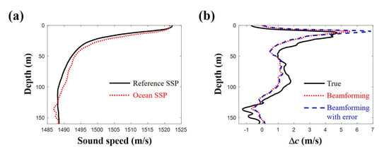
To demonstrate the feasibility of the proposed scheme to real application, peak values of beamforming results as in Figure 4b are used to recover one of SSPs in SWellEx-96 as shown in Figure 16a; the SSP has the largest deviation from the mean SSP. Eleven arrivals less than 30 are detected and two arrivals are filtered out after backpropagation. The estimated DOAs and corresponding travel times of nine arrivals whose backpropagated rays are within 10 m from the source position are used for the inversion. As shown in Figure 16b, the sound speed difference along depth evaluated with the modified scheme shows a good agreement with the true values while it overestimates major SSP variation near the sea surface. To account for the uncertainties in experimental environments, random errors between 2 and + 2 are added to the DOAs, which make the backpropagated rays deviate far from the source at the source range. Here, to acquire the arrivals used for the SSP inversion, the criterion increases from 10 m to 20 m. The number of available arrivals is reduced to six and their backpropagated rays are located farther from the source position. Still, the estimated SSP are in good agreement with the true values by capturing the major variation in SSP near the sea surface and following the overall trend.

4. Conclusions

In this work, the sound speed profile (SSP) is represented by a linear combination of shape functions in an SSP dictionary. The range/depth and horizontal/vertical travel time of arrival are linearly approximated from the reference SSP using Taylor series with the shape function coefficients at the corresponding arrival angle. Compressive sensing (CS) is applied to estimate the ocean SSP with the linear approximations for all direction of arrivals (DOAs). Thus, the inversion scheme proposed in this work can be used when the DOAs are resolved. The objective function is normalized to equally consider all the ray information.
The performance of present compressive SSP estimation is examined for the SWellEx-96 experimental environment. For simplicity, the beamforming results needed for the inversion are calculated using a conventional ray model by treating arrival angles from the ray model as DOAs, which are assumed to be identifiable. Five hundred sound speed profiles are generated synthetically using empirical orthogonal functions. Three numerical experiments are conducted using different objective functions. In the first experiment, the information on the position of the arrival is used. All ray information on the position and travel times is used without normalization and with normalization in the second and third experiments, respectively. The performance of the compressive SSP estimation is enhanced by simultaneous usage of position and travel time of ray. In particular, in the third experiment, over 80 percent of 500 cases show a correlation coefficient exceeding 0.7 . The performance is degraded with decrease in the number of arrivals when it is estimated with the correlation coefficient. However, the inversion scheme using all ray information shows a reliable result with relatively few arrivals.

Author Contributions

Y.C. conceived of the inversion scheme and conducted the numerical experiment. W.S. initiated this work, reviewed the paper and discussed the results.

Funding

This work was supported by the Defense Acquisition Program Administration and Ministry of Trade, Industry and Energy under the project “Development of towed Interferometric Synthetic Aperture Sonar (InSAS)” grant number [15-CM-SS-01].

Conflicts of Interest

The authors declare no conflict of interest.

References

  1. Collins, M.D.; Kuperman, W.A. Focalization: Environmental focusing and source localization. J. Acoust. Soc. Am. 1991, 90, 1410–1422. [Google Scholar] [CrossRef] [PubMed]
  2. Huang, C.F.; Gerstoft, P.; Hodgkiss, W.S. Effect of ocean sound speed uncertainty on matched-field geoacoustic inversion. J. Acoust. Soc. Am. 2008, 123, EL162–EL168. [Google Scholar] [CrossRef] [PubMed]
  3. Park, C.; Seong, W.; Gerstoft, P.; Hodgkiss, W.S. Geoacoustic inversion using backpropagation. IEEE J. Ocean. Eng. 2010, 35, 722–731. [Google Scholar] [CrossRef]
  4. Tan, B.A.; Gerstoft, P.; Yardim, C.; Hodgkiss, W.S. Broadband synthetic aperture geoacoustic inversion. J. Acoust. Soc. Am. 2013, 134, 312–322. [Google Scholar] [CrossRef] [PubMed]
  5. Tolstoy, A. Sensitivity of matched field processing to sound-speed profile mismatch for vertical arrays in a deep water Pacific environment. J. Acoust. Soc. Am. 1989, 85, 2394–2404. [Google Scholar] [CrossRef]
  6. Munk, W.; Wunsch, C. Ocean acoustic tomography: A scheme for large scale monitoring. Deep-Sea Res. 1979, 26A, 123–161. [Google Scholar] [CrossRef]
  7. Shang, E.C. Ocean acoustic tomography based on adiabatic mode theory. J. Acoust. Soc. Am. 1989, 85, 1531–1537. [Google Scholar] [CrossRef]
  8. Tolstoy, A.; Diachok, O.; Frazer, L.N. Acoustic tomography via matched field processing. J. Acoust. Soc. Am. 1991, 89, 1119–1127. [Google Scholar] [CrossRef]
  9. Tolstoy, A. Linearization of the matched field processing approach to acoustic tomography. J. Acoust. Soc. Am. 1992, 91, 781–787. [Google Scholar] [CrossRef]
  10. Bianco, M.; Gerstoft, P. Compressive acoustic sound speed profile estimation. J. Acoust. Soc. Am. 2016, 139, EL90–EL94. [Google Scholar] [CrossRef] [PubMed]
  11. Jensen, F.B.; Kuperman, W.A.; Porter, M.B.; Schmidt, H. Wave Propagation Theory, Ray Method, and Signals in Noise. In Computational Ocean Acoustics; Springer: New York, NY, USA, 2011; pp. 32–58. [Google Scholar]
  12. Donoho, D.L. Compressed sensing. IEEE Trans. Inf. Theory 2006, 52, 1289–1306. [Google Scholar] [CrossRef]
  13. Candes, E.J.; Wakin, M.B. An introduction to compressive sampling. IEEE Sign. Process. Mag. 2008, 25, 21–30. [Google Scholar] [CrossRef]
  14. Edelmann, G.F.; Gaumond, C.F. Beamforming using compressive sensing. J. Acoust. Soc. Am. 2011, 130, EL232–EL237. [Google Scholar] [CrossRef] [PubMed]
  15. Gerstoft, P.; Xenaki, A.; Mecklenbrauker, C.F. Multiple and single snapshot compressive beamforming. J. Acoust. Soc. Am. 2015, 138, 2003–2014. [Google Scholar] [CrossRef] [PubMed]
  16. Malioutov, D.; Cetin, M.; Willsky, A.S. A sparse signal reconstruction perspective for source localization with sensor arrays. IEEE Trans. Signal Process. 2005, 53, 3010–3022. [Google Scholar] [CrossRef]
  17. Xenaki, A.; Gerstoft, P.; Mosegaard, K. Compressive beamforming. J. Acoust. Soc. Am. 2014, 136, 260–271. [Google Scholar] [CrossRef] [PubMed]
  18. Xenaki, A.; Gerstoft, P. Grid-free compressive beamforming. J. Acoust. Soc. Am. 2015, 137, 1923–1935. [Google Scholar] [CrossRef] [PubMed] [Green Version]
  19. Choo, Y.; Seong, W. Compressive spherical beamforming for localization of incipient tip vortex cavitation. J. Acoust. Soc. Am. 2016, 140, 4085–4090. [Google Scholar] [CrossRef] [PubMed]
  20. Gemba, K.L.; Hodgkiss, W.S.; Gerstoft, P. Adaptive and compressive matched field processing. J. Acoust. Soc. Am. 2017, 141, 92–103. [Google Scholar] [CrossRef] [PubMed]
  21. Park, Y.; Seong, W.; Choo, Y. Compressive time delay estimation off the grid. J. Acoust. Soc. Am. 2017, 141, EL585–EL591. [Google Scholar] [CrossRef] [PubMed]
  22. Yardim, C.; Gerstoft, P.; Hodgkiss, W.S.; Traer, J. Compressive geoacoustic inversion using ambient noise. J. Acoust. Soc. Am. 2014, 135, 1245–1255. [Google Scholar] [CrossRef] [PubMed]
  23. Bianco, M.; Gerstoft, P. Dictionary learning of sound speed profiles. J. Acoust. Soc. Am. 2017, 141, 1749–1758. [Google Scholar] [CrossRef] [PubMed]
  24. Grant, M.; Boyd, S. CVX: Matlab Software for Disciplined Convex Programming, version 2.1. Available online: http://cvxr.com/cvx (accessed on 3 April 2018).
  25. Tipping, M.E. Sparse Bayesian learning and the relevance vector machine. J. Mach. Learn. Res. 2001, 1, 211–244. [Google Scholar] [CrossRef]
Figure 1. (a) the reference (solid line) and ocean (dotted line) sound speed profiles. The corresponding ray trajectories given in (b,c) show the vertical difference at the source range and the horizontal difference at the source depth, respectively.
Remotesensing 10 00704 g001
Figure 2. Numerical experiment environment: The sound speed profile is calculated as the mean of 26 CTD (Conductivity, Temperature, Depth) casts from SwellEx-96. The horizontal range between source and receiver is 2 km and their depths are 30 m and 80 m, respectively. The water depth is 160 m. Sound speed, density, and attenuation are 1800 m/s, 2.0 g/cm 3 , and 0.1 dB/ λ , respectively.
Remotesensing 10 00704 g002
Figure 3. The differences in the vertical travel times at the source range for (a) low, (c) moderate, and (e) high arrival angles. The corresponding ray trajectories for the reference sound speed profile are shown in (b), (d), and (f), respectively.
Remotesensing 10 00704 g003
Figure 4. (a) simulated arrival structures for the reference sound speed profile and (b) their corresponding direction of arrivals, which show high intensities compared to regions around them. The direction of arrivals are estimated using a simple delay-and-sum beamforming with the above arrival structures.
Remotesensing 10 00704 g004
Figure 5. (a) trajectories of eigenrays with arrival angles less than 30 . Dashed lines correspond to ray trajectories for refracted rays; (b) arrival angles of eigenrays according to their travel times (o marks) overlaid on Figure 4b. They match well with the direction of arrivals from the beamforming.
Remotesensing 10 00704 g005
Figure 6. (a) sound speed profile generated by the two Gaussian functions and (b) sound speed profile generated by the three components of empirical orthogonal functions.
Remotesensing 10 00704 g006
Figure 7. (a) actual activated components (solid line) among the 94 Gaussian shape functions in sound speed profile dictionary and estimated components (dotted line) from the compressive sound speed profile estimation; (b) the sound speed differences along depth from the reference sound speed profile. The solid and dotted lines are actual and reconstructed values, respectively.
Remotesensing 10 00704 g007
Figure 8. Backpropagated ray trajectories of arrivals less than 30 . The reference and estimated sound speed profiles are used for (a) and (b), respectively. The inset shows an enlarged diagram revealing incorrect/correct convergence to the source position.
Remotesensing 10 00704 g008
Figure 9. (a) actual activated components (solid line) among the 26 empirical orthogonal functions in sound speed profile dictionary and estimated components (dotted line) from the compressive sound speed profile estimation; (b) the sound speed differences along depth from the reference sound speed profile. The solid and dotted lines are actual and reconstructed values, respectively.
Remotesensing 10 00704 g009
Figure 10. Backpropagated ray trajectories of arrivals less than 30 . (a) reference and (b) estimated sound speed profile cases.
Remotesensing 10 00704 g010
Figure 11. Sound speed differences from the reference sound speed profile estimated from compressive sound speed profile inversion (a) without and (b) with considering errors in arrival angles. Error angles are uniformly distributed between 0.05 and + 0.05 .
Remotesensing 10 00704 g011
Figure 12. (a) sound speed differences from the reference sound speed profile estimated from compressive sound speed profile inversion with considering errors in arrival angles. Error angles are uniformly distributed between 0.5 and + 0.5 ; (b) estimated errors in direction of arrivals used for the inversion. They are in good agreement with the actual errors.
Remotesensing 10 00704 g012
Figure 13. Arrivals less than 30 are used for the inversion of sound speed profile. Percentages of cases corresponding to correlation coefficients (x-axis) according to three numerical experiments using different objective functions. Limited information related to the position is used for (a) and all available information is used (b) without and (c) with the normalization, respectively.
Remotesensing 10 00704 g013
Figure 14. Mean squared errors of estimated sound speed profiles from true values are calculated according to different objective functions using arrivals less than (a) 30 and (b) 20 , respectively. The inversion using all ray information after normalization outperforms the others. The reduction of available ray number has a slight effect on the performance in terms of mean squared error.
Remotesensing 10 00704 g014
Figure 15. Arrivals less than 20 are used for the inversion of sound speed profile. Percentages of cases corresponding to correlation coefficients (x-axis) according to three numerical experiments using different objective functions. Limited information related to the position is used for (a) and all available information is used (b) without and (c) with the normalization, respectively.
Remotesensing 10 00704 g015
Figure 16. (a) one sound speed profile case in SWellEx-96, which has the largest deviation from the mean SSP; (b) sound speed differences along depth from the reference sound speed profile estimated with compressive sound speed profile inversion using beamforming results. The sound speed profile (dotted line) is reconstructed in the situation, where inevitable deviations from actual arrival angles and travel times exist owing to plane-wave approximation in beamforming. Random errors between 2 and + 2 are added to direction of arrivals from the beamforming to account for the uncertainties in experimental environments (dashed line).
Remotesensing 10 00704 g016