Article

Wear Analysis of a Heterogeneous Annular Cylinder

1
Department of System Dynamics and Friction Physics, Berlin University of Technology, Berlin 10623, Germany
2
Tomsk State University, Tomsk 634050, Russia
*
Author to whom correspondence should be addressed.
Lubricants 2018, 6(1), 28; https://doi.org/10.3390/lubricants6010028
Submission received: 28 February 2018 / Revised: 14 March 2018 / Accepted: 15 March 2018 / Published: 18 March 2018
(This article belongs to the Special Issue Computer Simulation in Tribology and Friction)

Abstract

:
Wear of a cylindrical punch composed by two different materials alternatively distributed in annular forms is studied with the method of dimensionality reduction (MDR). The changes in surface topography and pressure distribution during the wear process is obtained and validated by the boundary element method (BEM). The pressure in each annular ring approaches a constant in a stationary state where the surface topography does not change any more. Furthermore, in an easier manner, using direct integration, the limiting profile in a steady wear state is theoretically calculated, as well as the root mean square (RMS) of its surface gradient, which is closely related to the coefficient of friction between this kind of surface and an elastomer. The dependence on the wear coefficients and the width of the annular areas of two phases is obtained.

Graphical Abstract

1. Introduction

Friction between a vehicle’s tire and the road is an everyday contact problem. The skid resistance of an asphalt pavement plays an important role in the driving safety [1]. Due to the movement, the road is polished and its resistance against skid of the contact is decreased. To improve the quality and durability of the contact between road and tire, knowledge about the time-dependent behavior of the contact is vital. In the last few decades, many tests have been carried out to study the tire-road interaction, e.g., by changes in the structure of aggregates and asphalt binders [2], and the addition of additives [3]. Recent research [4,5] covers an experimental approach to this contact problem to determine the long-term behavior of different construction materials being exposed to the polishing effects of the tires of vehicles. The behavior of the road material’s skid resistance is examined. Do et al. [4] studied the dominating effect of the aggregates on friction, as soon as the binder is polished after a given time of usage, which is explained by a modification of the aggregate’s microtexture. Kane [5] examines the relation between the composition of the asphalt and the friction that it provides in the tire to road contact. It results in the introduction of a hardness parameter related to the friction coefficient.
It is well known that a typical dependency of the coefficient of friction is non-monotonous: as very small velocities, the coefficient of friction first increases with velocity, has than a long plateau and falls down at very high sliding velocities [6]. The constant coefficient of friction at the plateau is of main interest for application. In [7] it is shown that this plateau value of the friction coefficient is mainly determined by the mean square root slope of the surface of the rigid rough surface. In the present paper we consider development of the square root value of the slope due to wear and interpret this as development of the coefficient of friction. We investigate the wear of a multi-phase cylinder in sliding contact with an elastic half space. To achieve a general understanding of the governing parameters, we consider a simple axially symmetric heterogeneity of the material. We investigate both the wear process and the limiting profile, which is achieved under a long enough running-in process. In the stationary state, the wear continues but the shape of indenter does not change any more. We assume the simplest Archard’s law of wear [8] in its local form, stating that the volume of the material loss Δ V is proportional to the normal load F N and sliding distance s , and inversely proportional to the hardness of the material σ 0 :
Δ V = k w e a r F N s σ 0
Using this law of wear, the change of the surface topography of the heterogeneous specimen during the sliding is calculated numerically using the method of dimensionality reduction (MDR). The MDR was proposed by Popov and Heß for the fast calculation of various contact problems [9]. Note that it provides not approximation but exact solutions for axisymmetric contacts by mapping of three-dimensional contacts onto one-dimensional contacts, and has been applied to studying on different wear problems, e.g., fretting wear [10] and gross slip wear [11], which were also validated by experiment [12] or by the finite element method [13]. The advantage of the MDR is very fast calculation; the disadvantage is that (for wear problems) it can only be applied to axially-symmetric contact problems. This is the reason for the use of the set-up described below. We consider a heterogeneous annular cylinder with rings of alternating material representing aggregate and binder, respectively, to study the effects of material composition. Furthermore, to study the surface gradient of the contact body in the final stationary state, a direct integration is applied to calculate the final surface topography quickly.
The parts of this paper are organized as follows: Section 2 describes the model of heterogeneous cylinder. Section 3 presents the simulation of wear process from the first contact to the final stationary state using the MDR. Section 4 gives a method for direct calculation of the profile in stationary state and discusses the influence of ratio of wear coefficients of two materials and their area ratio on the surface gradient. At last a short conclusion is presented in Section 5.

2. Model of Heterogeneous Cylinder

We consider the following system, Figure 1a, a heterogeneous cylinder is pressed into the elastic half space with the normal force F N , and moves tangentially with a constant velocity v 0 . The initially flat cylinder surface will be worn and approaches a limiting profile over time that is to be found. The cylinder has the radius a and consists of a number of rings-aped cylinders N R with the radius r i = i a / N R , composed alternatively of two materials having similar elastic properties, but different wear coefficients k 1 , 2 . Furthermore, the widths h 1 , 2 of the rings can be variable, as shown in Figure 1b. In the case of a tire-asphalt contact, these materials could correspond to the rock particles and binder of the asphalt. In Figure 1, a sample with flat surface is shown. The initial surface topography, however, does not have any influence on the topography in the stationary state; only the material composition does matter.

3. Calculation of the Wear Process Using the MDR

3.1. Method of Dimensionality Reduction

The method of dimensionality reduction gives an exact solution of axially-symmetric contact problems [9,14], including the case of this annular cylinder with rings. In this study it will be used to quickly determine the stress distribution of a contact.
In the framework of MDR the real three-dimensional elastic body is equivalently represented by a one-dimensional linearly elastic foundation. The foundation is handled as a linear array of spring elements with an equal distance Δ x , Figure 2. In a normal contact of a rigid body and an elastic half space, the stiffness of the springs is only considered in z-direction with E * being the effective elastic modulus:
Δ k z = E * Δ x   with   E * = E 1 ν 2
where E and ν are the elastic modulus and Poisson’s ratio of the elastic half space. In the following analysis of this section, we assume that the two phases have the same E * . The second step in an MDR calculation is transformation of the three-dimensional contact profile f ( r ) into the one-dimensional MDR-profile g ( x ) :
g ( x ) = | x | 0 | x | f ( r ) x 2 r 2 d r
This profile can be used to calculate the relevant parameters of the contact problem. The displacement in z-direction can be found by the following equation with d being the indentation depth:
u z ( x ) = d g ( x )
The proportionality of displacement u z ( x ) and force at this point Δ F z ( x ) can be used to define the linear force density q z ( x ) :
Δ F z ( x ) = Δ k z u z ( x ) = E * u z ( x ) Δ x
q z ( x ) = Δ F z ( x ) Δ x = E * u z ( x ) = E * [ d g ( x ) ]
Finally, this linear force density is used to calculate the stress distribution p ( r ) :
p ( r ) = 1 π r q ( x ) x 2 r 2 d x

3.2. Simulation Procedure

The algorithm employed to solve the contact problem with the method of dimensionality reduction (MDR) is outlined in the flowchart in Figure 3.
Single steps will be explained in the following. Steps (2)–(6) are repeated until the profile reaches the limiting profile within a given tolerance.

3.2.1. Defining Initial State (0)–(1)

The initial cylindrical profile f ( r ) and the respective one-dimensional MDR-profile g ( x ) are given by:
f ( 0 ) ( r ) = { 0 for   r < a for   r > a
g ( 0 ) ( x ) = { 0 for   x < a for   x > a
The initial indentation depth under a constant normal force f ( r ) can be estimated according to [6]:
d ( 0 ) = F N 2 a E *
The initial pressure distribution is:
p ( 0 ) = p 0 ( 1 r 2 a 2 ) 1 / 2   with   p 0 = F N 2 π a 2

3.2.2. Change of Profile Due to Wear: Steps (2)–(3)

The heterogeneous, cylindrical indenter with profile f ( r ) is pressed into an elastic half space with a constant normal force F N and then moved sideways with a constant velocity v 0 . Archard’s law of wear (1) for this heterogeneous indenter can be written as:
Δ V = k w e a r ( r ) F N s σ 0 ( r )
where k w e a r ( r ) and σ 0 ( r ) are the radius-dependent wear coefficient and hardness. Introducing notation k ( r ) = k w e a r ( r ) / σ 0 ( r ) , the linear wear can be written as:
d f ( r ) = k ( r ) p ( r ) d x = k ( r ) p ( r ) v 0 d t
where p ( r ) is the normal stress. This equation is used to calculate the profile change at any time step d t . Thus the profile change of the k-th time step is:
d f ( k ) ( r ) = k ( r ) p ( k 1 ) ( r ) v 0 d t
with a piecewise constant distribution of wearing coefficients as depicted in Figure 1. The profile is updated by:
f ( k ) ( r ) = f ( k 1 ) ( r ) + d f ( k ) ( r )

3.2.3. Stress Distribution of the Updated Profile: Steps (4)–(6)

In order to obtain the profile change in Equation (14), the new one-dimensional profile g ( k ) ( x ) and the new indentation depth d ( k ) are needed. The former one can be calculated by transformation of the updated profile f ( k ) ( r ) with Equation (3), and the latter can be found by using the equilibrium of constant normal force and linear force density q z ( x ) (see Equation (6)):
F N = a a q z ( x ) d x = 2 E * d ( k ) a 2 E * 0 a g ( k ) ( x ) d x
Thus the new indentation depth is:
d ( k ) = F N 2 E * a 1 a 0 a g ( k ) ( x ) d x
Now, the pressure distribution p ( k ) ( r ) can be calculated by integrating Equation (7) numerically.

3.3. Numerical Results

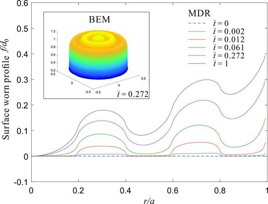
Figure 4 shows an example of the time-dependence of wear of the indented cylinder with five rings as described in Figure 1b: 3D profiles f ( r ) , and corresponding 1D profile g ( x ) , as well as stress distributions p ( r ) at distinct time steps. The analytical solution for an unworn cylinder is displayed by a dotted line for comparison. The profiles are normalized with the initial indentation depth d 0 calculated as in Equation (10), the stress is normalized by p 0 as in Equation (11) and r and x , respectively, by the radius of the cylinder a . Furthermore, the numerical results from the simulation with the boundary element method [15] are added in this figure for comparison. It can be seen that the MDR the BEM match within a small tolerance. However, the simulation with the MDR is much faster than the BEM.
Two parameters are monitored in each time step: Firstly, the difference of maximal displacement of the elastic half-space u z , max and initial indentation depth d 0 and secondly the elapsed time t w which is equivalent to the sliding distance due to constant sliding velocity. Both parameters are normalized by the according values of the limiting profile u z , max s t a t and t w s t a t .
As indicated by Equation (13), wear occurs on all parts of the cylinder. The profile however changes only as long as the product C ( r ) = p ( r ) k ( r ) is not constant. Thus, for the piecewise constant distribution of wear coefficients the resulting stress distribution of the limiting profile must be piecewise constant as well with p 1 > p 2 in this case ( k 1 < k 2 ). This can be observed for the limiting profile.
In the investigated case the stress level of rings with the lower wear coefficient is more than three times larger than p 0 and less than half for rings with the higher coefficient. A closer look at the time steps shows that the profile changes very quickly close to the edge of the body where the stress is theoretically infinite in the beginning. Further, it changes quicker in regions with higher wear coefficient (in this case k 2 ). This profile change results in a reduction of stress in these regions. Due to the constant normal force and considering the equilibrium of forces, this also results in a rise of stress in regions that are not subjected to a great deal of profile change, initially. As a consequence, these regions are in the following also subjected to profile change.
The constant stress level of rings with the higher wear coefficient (in this case k 2 and p 2 ) is reached significantly faster. Therefore, the time needed to reach the limiting profile is mostly dependent on the lowest wear coefficient.
Looking at the monitored parameters Δ u ˜ z and t ˜ z we observe that the profile change slows down significantly as the stress differences within the rings are getting smaller. For 70% of the displacement difference, only 27% of the time is needed to reach the limiting profile. This behavior can also be observed in Figure 5 which shows the change of the surface gradient of the cylinder, where the cycles indicates the states at the time moment of the Figure 4. The root mean square (RMS) of the surface gradient is defined as:
d ( k ) = F N 2 E * a 1 a 0 a g ( k ) ( x ) d x
f = ( d f s t a t ( r ) d r ) 2

4. Limiting Profile and Surface Gradient

4.1. Calculation of the Limiting Profile by Direct Integration

As shown in [7], the surface displacement u z of an elastic half space at a certain point r generated by a thin ring is given by:
u z ( r ) = F N 2 r ˜ E * 4 π 2 ( 1 + r / r ˜ ) K ( 2 r / r ˜ 1 + r / r ˜ )
Therein, r ˜ is the radius of the ring and K is the elliptic integral:
K ( κ ) = 0 π 2 d φ 1 κ 2 sin 2 φ
In order to find the surface displacement at point r resulting from an entire cylinder rather than just a thin ring Equation (19) is integrated:
u z , t o t ( r ) = 4 π E * 0 a K ( 2 r / r ˜ 1 + r / r ˜ ) p ( r ˜ ) 1 + r / r ˜ d r ˜
with the normal force F N being:
F N = 2 π 0 a r ˜ p ( r ˜ ) d r ˜
The shape of the given cylinder alters until a steady wear, and thus a profile change:
d f ( r ) d t = k 1 , 2 ( r ) p ( r ) v 0 const
is reached. Consequently, for the limiting profile, the stress within each ring needs to be constant:
p stat ( r ) = { p 1 for   r k 1 = { r | k ( r ) = k 1 } p 2 = k 1 / k 2 p 1 for   r k 2 = { r | k ( r ) = k 2 }
Here, k1 and k2 are the sets of r corresponding to, respectively, odd and even rings. By inserting Equation (24) in the equation for the normal force:
F N = 2 π 0 a 0 2 π p s t a t ( r ) r d r
The stress in rings with odd numbers can be calculated as:
p 1 = F N 2 π ( k 1 r d r + k 1 k 2 k 2 r d r ) 1
This stress distribution can now be inserted in Equation (21) to find the stationary solution for the surface displacement u z , t o t ( r ) . Finally, the limiting profile of the indenter is given by:
f s t a t ( r ) = u max u z , t o t ( r )
where u max is the maximum value of u z , t o t ( r ) .

4.2. Results

With the direct integration method described above, the limiting profiles, as well as their surface gradient for a variety of parameters k 2 / k 1 and h2/h1 were determined. Dependence of friction on wear coefficients and ring widths are shown in Figure 6 and Figure 7. The surface gradient is normalized by f 0 , and the case of a homogeneous cylinder ( k 2 / k 1 = 1 ) is plotted versus the ratio of wear coefficients k 2 / k 1 and ring widths h2/h1, respectively. Each curve represents the number of rings used as it was introduced in Figure 1.
For a fixed ratio of ring widths h2/h1 = 1 and variable ratio of wear coefficients k 2 / k 1 (Figure 6) the plots are symmetrical for large numbers of rings. In all cases the surface gradients are converging towards different values for k 2 / k 1 > 100 and k 2 / k 1 < 0.01 . This means for very large or very small ratios the influence of the faster wearing rings can be neglected and the problem is equivalent to single rings of the slower wearing material. The limiting value for large numbers of rings is f / f 0 2.4 . For ratios in the range 0.01 < k 2 / k 1 < 100 the surface gradient is obviously very susceptible to the materials chosen.
In the case of very few rings the plots are asymmetrical and depend on the order of materials within the cylinder. This can be observed in the smaller figures for N R = 4 showing the limiting profiles. For a body with the same materials one subplot shows the case of the faster wearing material on the outside ( k 2 / k 1 = 100 ) and the other one shows the case of the slower wearing material on the outside ( k 2 / k 1 = 0.01 ). Obviously, the slope of the combination with the slower wearing material on the outside is much smaller because the outer ring “limits” profile change in the inner rings. The result is a much smaller surface gradient. For the case of only two rings there are even some ratios resulting in a slightly lower surface gradient than that of a homogeneous cylinder.
The variation of ring widths shown in Figure 7 is done with a fixed ratio of wear coefficients k 2 / k 1 = 0.01 . Therefore, for h2/h1 = 1 the values for the different ring numbers are the same as in Figure 6. For this configuration the outer ring is always consisting of the slower wearing material. If the ratio h2/h1 is increased, the share of slower wearing material is increased. Again, looking at the limiting profiles depicted for N R = 8 it is obvious that for h2/h1 = 10 the parts of faster wearing materials are suppressed and have almost no influence on the profile. This means the surface gradient is very close to that of a homogeneous body. Thus, in all cases, convergence towards f / f 0 = 1 can be observed.
However, if the share of slower wearing material is increased, the surface gradient is significantly higher. From the limiting profile for N R = 8 and h2/h1 = 0.1. It is obvious that in these cases the problem is equivalent to only the thin rings with the number N R / 2 pressed into the elastic half-space. In this case there is no convergence and the surface gradient increases with the number of rings.

5. Conclusions

In this paper, wear of an annular cylinder made of alternating rings of materials with different wear coefficients was analyzed. This was done by implementing two different methods. The method of dimensionality reduction (MDR) was used to analyze the time-dependent wear and to understand the influence of stress distribution and distribution of wear coefficients on the profile change. It was found that profile change slows down significantly as the limiting profile is approached. The limiting profile that is eventually reached is the state when the profile does not change anymore. In this state the stress distribution is piecewise constant.
As another approach to calculate the limiting profile, a method of direct integration was employed as well. Although the same limiting profile can be computed using both methods, this method of direct integration is much faster and was, thus, used to study the influence of the ratio of wear coefficients and ring widths on the limiting profile.
The root mean square of the surface gradient was the most important factor in this analysis as the friction coefficient is highly dependent on it. It was found that the surface gradient depends strongly on the ratio of wear coefficients. For coefficients with a difference of less than factor 10 the greatest dependence on the ratio of coefficients is observed. It was also found that for very few rings the order of rings is important and changes the surface gradient significantly.
The width of the rings has almost no influence on the RMS surface gradient. However, the RMS slope depends strongly on the ratio of width of rings of two phases. The highest RMS slope (and this the highest coefficient of friction is achieved if the width of the phase with small coefficient of wear is much smaller than the width of the rings with higher wear coefficient. Regarding the problem of the wear of pavement stated in the introduction, this means that the high stationary coefficient of friction will be achieved if hard (wear less) phase represents narrow “inclusions” in the bulk matrix with higher coefficient of wear.

Acknowledgments

This research was partially supported by “The Tomsk State University competitiveness improvement program” grant.

Author Contributions

Valentin L. Popov and Qiang Li conceived this study. Fabian Forsbach, Maximilian Schuster, and Daniel Pielsticker carried out the numerical simulation with the MDR. Qiang Li provided the numerical results by the BEM. All the authors discussed the results and wrote the manuscript.

Conflicts of Interest

The authors declare no conflict of interest.

List of Symbols

Δ k z Normal stiffness g , g ( 0 ) , g ( k ) One-dimensional profile
Δ F z Spring force h 1 , h 2 Widths of rings
Δ u ˜ z Normalized deformation i The index of rings
Δ V Material loss in volume k w e a r , k 1 , k 2 Wear coefficients
Δ x Spring distance N R Number of rings
f , f 0 Surface gradient p , p ( 0 ) , p ( k ) , p s t a t Pressure distribution
K Elliptic integral q z Linear force density
σ 0 Hardness r Polar coordinate
ν Poisson’s ratio r i Radius of rings
a Radius of cylinder s Sliding distance
d , d ( 0 ) , d ( k ) Indentation depth t w , t w s t a t Time
E Elastic modulus t ˜ w Normalized time
E * Effective elastic modulus u z , u z , t o t , u z , max , u z , max s t a t Vertical deformation
f , f ( 0 ) , f ( k ) , f s t a t Three-dimensional profile v 0 Sliding velocity
F N Normal load x Coordinate

References

  1. Wallman, C.G.; Åström, H. Friction Measurement Methods and the Correlation between Road Friction and Traffic Safety—A Literature Review Report of the Swedish National Road and Traffic Institute, VTI Meddelande 911A; Swedish National Road and Transport research Institute: Linköping, Sweden, 2001. [Google Scholar]
  2. Sarang, G.; Lekha, B.M.; Geethu, J.S.; Shankar, A.U.R. Laboratory performance of stone matrix asphalt mixtures with two aggregate gradations. J. Mod. Transp. 2015, 23, 130–136. [Google Scholar] [CrossRef]
  3. Kogbara, R.B.; Masad, E.A.; Kassem, E.; Scarpas, A.; Anupam, K.A. State-of-the-art review of parameters influencing measurement and modeling of skid resistance of asphalt pavements. Constr. Build. Mater. 2016, 114, 602–617. [Google Scholar] [CrossRef]
  4. Do, M.T.; Tang, Z.; Kane, M.; De Larrard, F. Pavement polishing–Development of a dedicated laboratory test and its correlation with road results. Wear 2007, 263, 36–42. [Google Scholar] [CrossRef]
  5. Kane, M.; Artamendi, I.; Scarpas, T. Long-term skid resistance of asphalt surfacings: Correlation between Wehner–Schulze friction values and the mineralogical composition of the aggregates. Wear 2013, 303, 235–243. [Google Scholar] [CrossRef]
  6. Li, Q.; Popov, M.; Dimaki, A.; Filippov, A.E.; Kürschner, S.; Popov, V.L. Friction Between a Viscoelastic Body and a Rigid Surface with Random Self-Affine Roughness. Phys. Rev. Lett. 2013, 111, 034301. [Google Scholar] [CrossRef] [PubMed]
  7. Popov, V.L. Contact Mechanics and Friction, Physical Principles and Applications, 2nd ed.; Springer-Verlag: Berlin, Germany, 2017; pp. 283–289. [Google Scholar]
  8. Archard, J.F.; Hirst, W. The Wear of Metals under Unlubricated Conditions. Proc. R. Soc. Lond. A 1956, 236, 397–410. [Google Scholar] [CrossRef]
  9. Popov, V.L.; Hess, M. Method of Dimensionality Reduction in Contact Mechanics and Friction; Springer-Verlag: Berlin, Germany, 2015; pp. 65–86. [Google Scholar]
  10. Popov, V.L. Analytic solution for the limiting shape of profiles due to fretting wear. Sci. Rep. 2014, 4, 3749. [Google Scholar] [CrossRef] [PubMed]
  11. Dimaki, A.V.; Dmitriev, A.I.; Chai, Y.S.; Popov, V.L. Rapid Simulation Procedure for Fretting Wear on the basis of the method of dimensionality reduction. Int. J. Solids Struct. 2014, 51, 4215–4220. [Google Scholar] [CrossRef]
  12. Dmitriev, A.I.; Voll, L.B.; Psakhie, S.G.; Popov, V.L. Universal limiting shape of worn profile under multiple-mode fretting conditions: theory and experimental evidence. Sci. Rep. 2016, 6, 23231. [Google Scholar] [CrossRef] [PubMed]
  13. Dimaki, A.V.; Dmitriev, A.I.; Menga, N.; Papangelo, A.; Ciavarella, M.; Popov, V.L. Fast High-Resolution Simulation of the Gross Slip Wear of Axially Symmetric Contacts. Tribol. Trans. 2016, 59, 189–194. [Google Scholar] [CrossRef]
  14. Popov, V.L.; Hess, M. Method of Dimensionality Reduction in contact mechanics and friction: A user’s handbook. FU Mech. Eng. 2014, 12, 1–14. [Google Scholar]
  15. Pohrt, R.; Li, Q. Complete boundary element formulation for normal and tangential contact problems. Phys. Mesomech. 2014, 17, 334–340. [Google Scholar] [CrossRef]
Figure 1. (a) The cylinder made of a number of ring-shaped cylinders with radii ri; and (b) exemplary surface with wear coefficients k1,2 and ring widths h1,2 for a cylinder with five rings.
Lubricants 06 00028 g001
Figure 2. (a) 3D contact problem and (b) its equivalent one-dimensional model.
Lubricants 06 00028 g002
Figure 3. Solution algorithm.
Lubricants 06 00028 g003
Figure 4. Worn profiles and pressure distribution during the wear process for the cylinder with 5 rings, k2/k1 = 10 and h2/h1 = 1.
Lubricants 06 00028 g004
Figure 5. Change of normalized RMS of the surface gradient during the wear process.
Lubricants 06 00028 g005
Figure 6. Normalized RMS of the surface gradient as a function of k2/k1 for different numbers of rings. The small figures show limiting profiles for extracted configurations.
Lubricants 06 00028 g006
Figure 7. Normalized RMS of the surface gradient as a function of h2/h1 for different numbers of rings. The small figures show limiting profiles for extracted configurations.
Lubricants 06 00028 g007