Figure 1.
Luojia 1-01 satellite coordinate system.
Figure 1.
Luojia 1-01 satellite coordinate system.
Figure 2.
Exploded view of the Luojia 1-01 Satellite.
Figure 2.
Exploded view of the Luojia 1-01 Satellite.
Figure 3.
Shock absorbers in the Luojia 1-01 satellite (without the side solar panels).
Figure 3.
Shock absorbers in the Luojia 1-01 satellite (without the side solar panels).
Figure 4.
Variation curve of heat flux density on the satellite’s surface.
Figure 4.
Variation curve of heat flux density on the satellite’s surface.
Figure 5.
Radiating regions of the Luojia 1-01 satellite. (a) Radiating region of the +Y panel. (b) Radiating region of the −Y panel.
Figure 5.
Radiating regions of the Luojia 1-01 satellite. (a) Radiating region of the +Y panel. (b) Radiating region of the −Y panel.
Figure 6.
Thermal analysis model of the Luojia 1-01 satellite.
Figure 6.
Thermal analysis model of the Luojia 1-01 satellite.
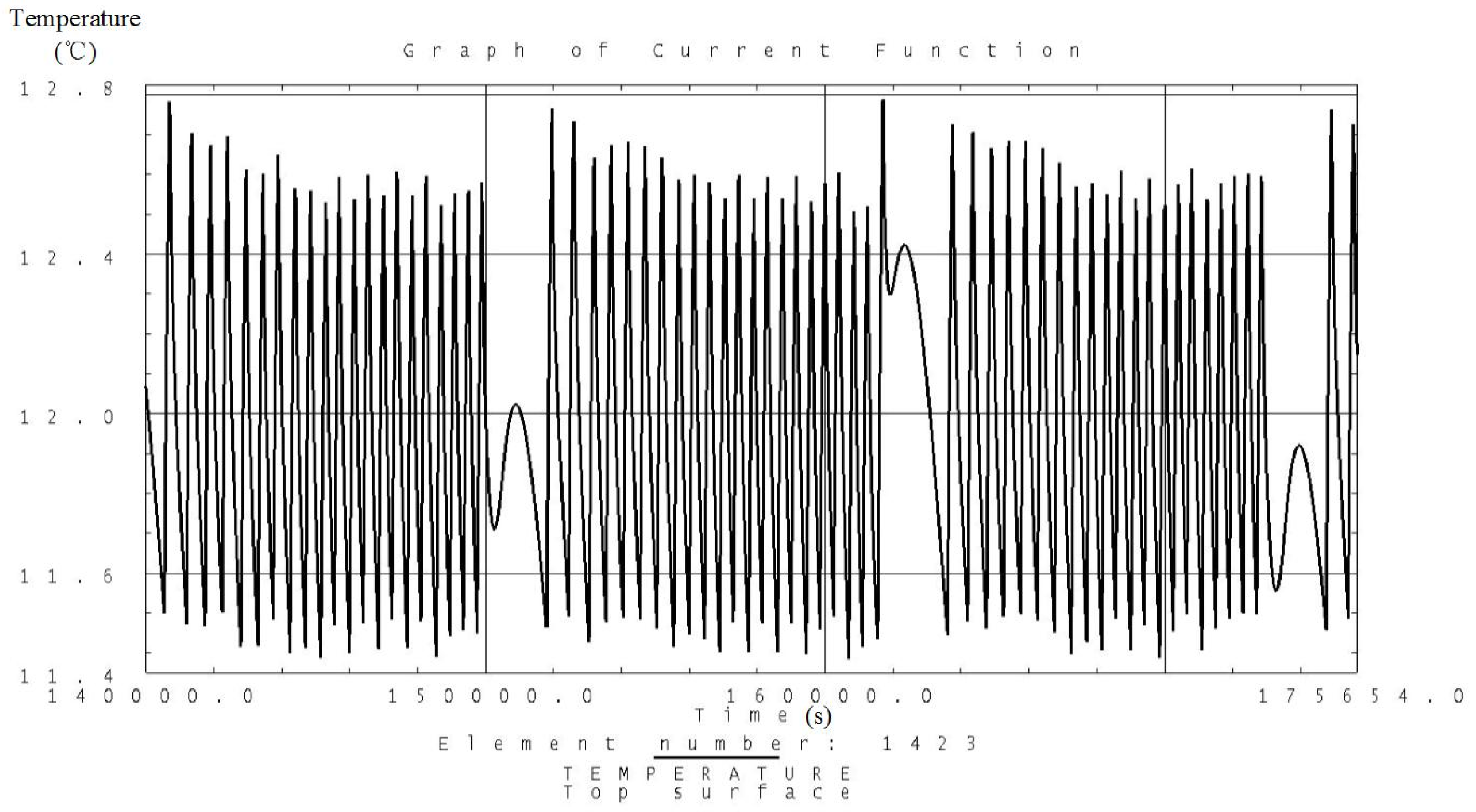
Figure 7.
Analysis result of the temperature variation curve of the camera under high temperature conditions.
Figure 7.
Analysis result of the temperature variation curve of the camera under high temperature conditions.
Figure 8.
Analysis result of the temperature variation curve of the camera under low temperature conditions.
Figure 8.
Analysis result of the temperature variation curve of the camera under low temperature conditions.
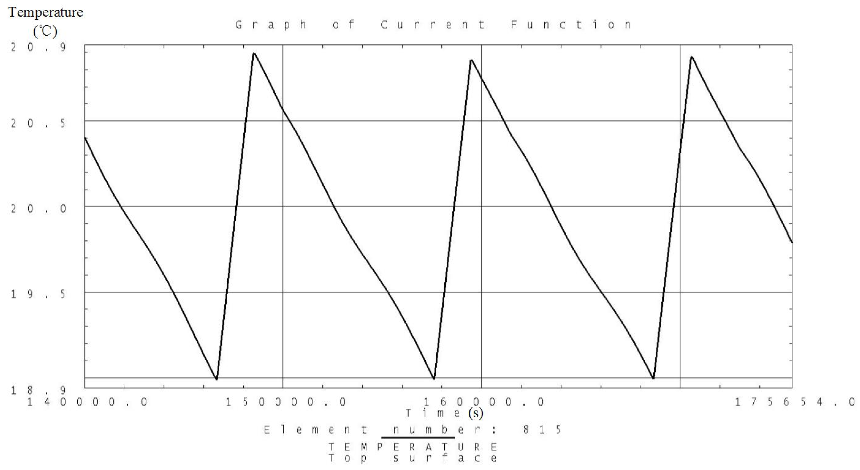
Figure 9.
Analysis result of the temperature variation curve of the battery under high temperature conditions.
Figure 9.
Analysis result of the temperature variation curve of the battery under high temperature conditions.
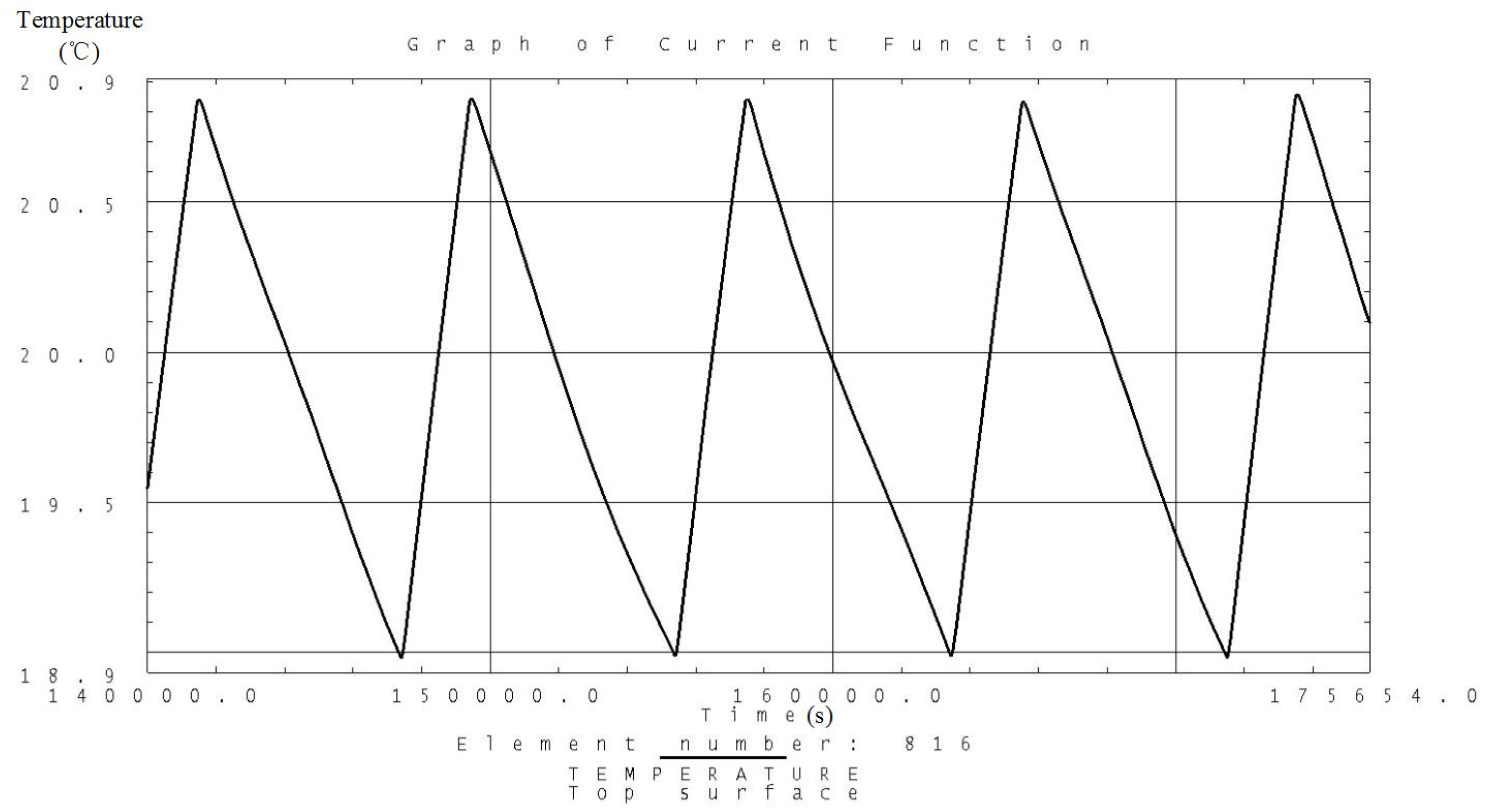
Figure 10.
Analysis result of the temperature variation curve of the battery under low temperature conditions.
Figure 10.
Analysis result of the temperature variation curve of the battery under low temperature conditions.
Figure 11.
Analysis result of the temperature variation curve of the solar panels under high temperature conditions.
Figure 11.
Analysis result of the temperature variation curve of the solar panels under high temperature conditions.
Figure 12.
Analysis result of the temperature variation curve of the solar panels under low temperature conditions.
Figure 12.
Analysis result of the temperature variation curve of the solar panels under low temperature conditions.
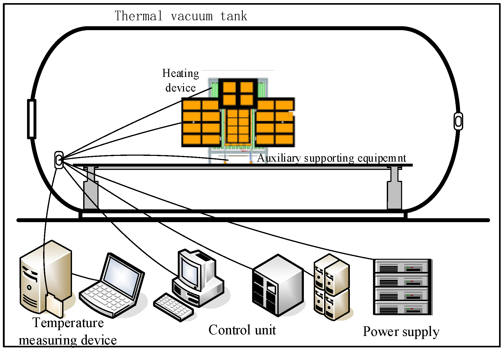
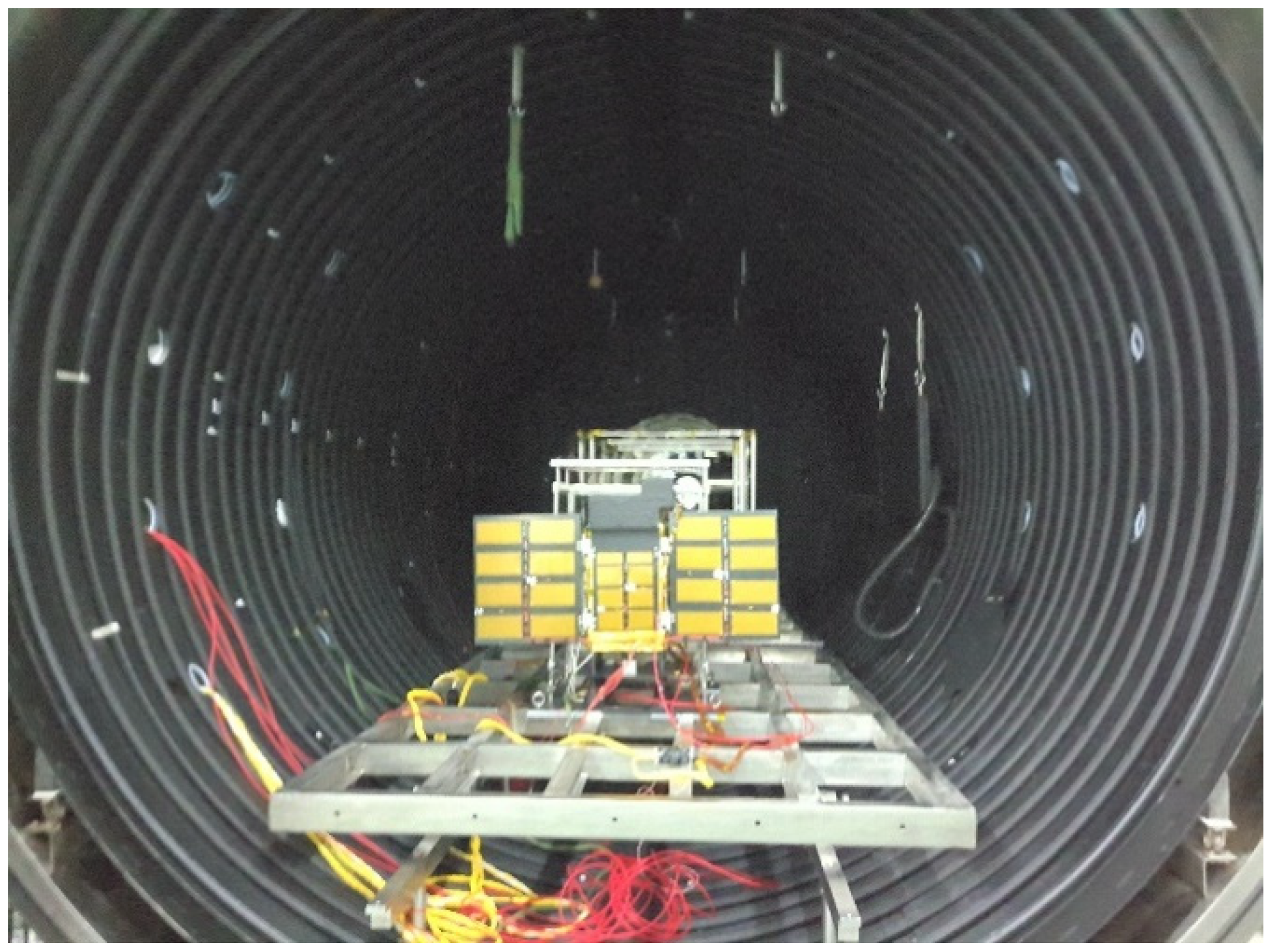
Figure 13.
Schematic diagram of the testing devices.
Figure 13.
Schematic diagram of the testing devices.
Figure 14.
Testing site of Luojia 1-01.
Figure 14.
Testing site of Luojia 1-01.
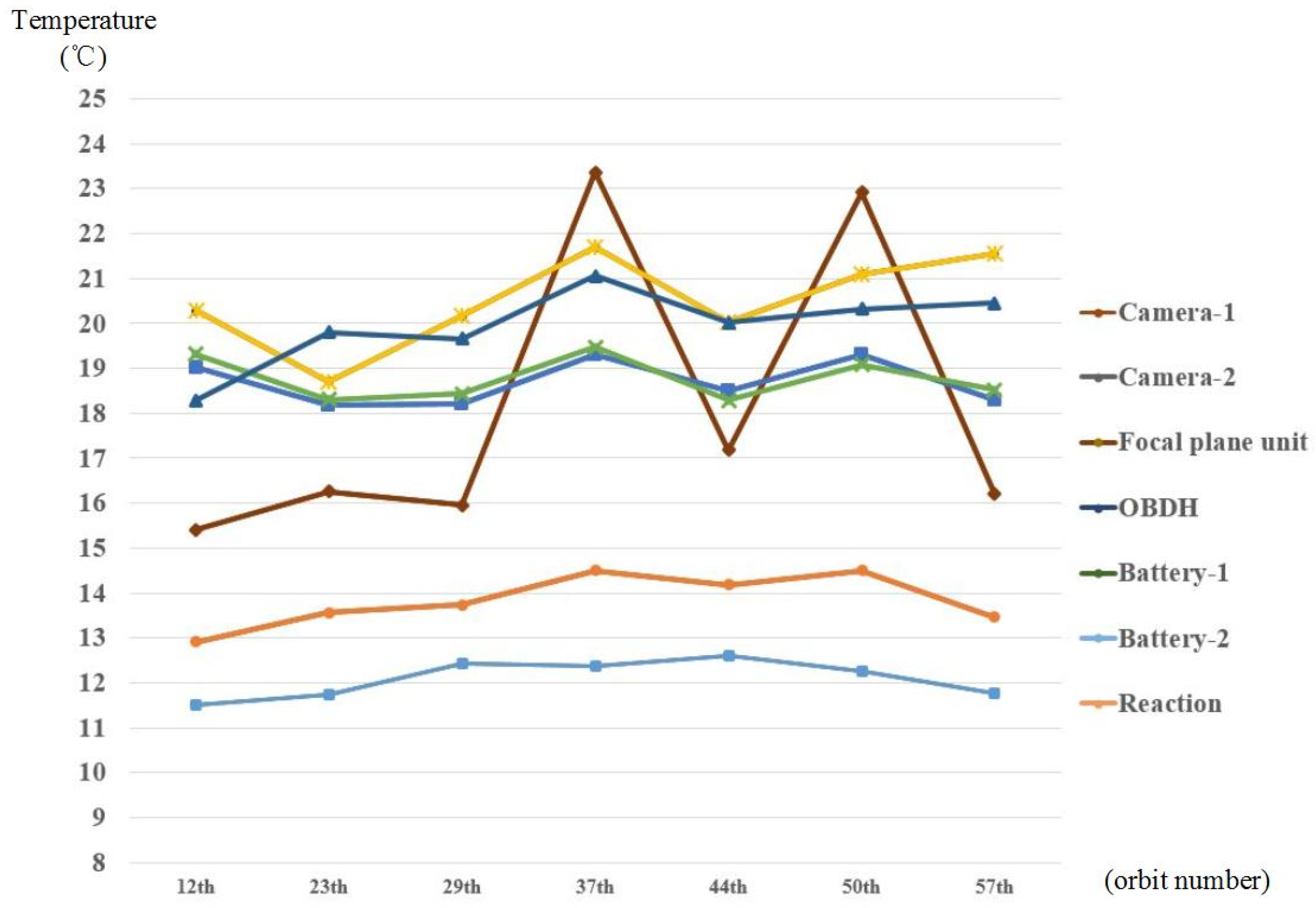
Figure 15.
Temperature variation curve of the inside instruments on the Luojia 1-01.
Figure 15.
Temperature variation curve of the inside instruments on the Luojia 1-01.
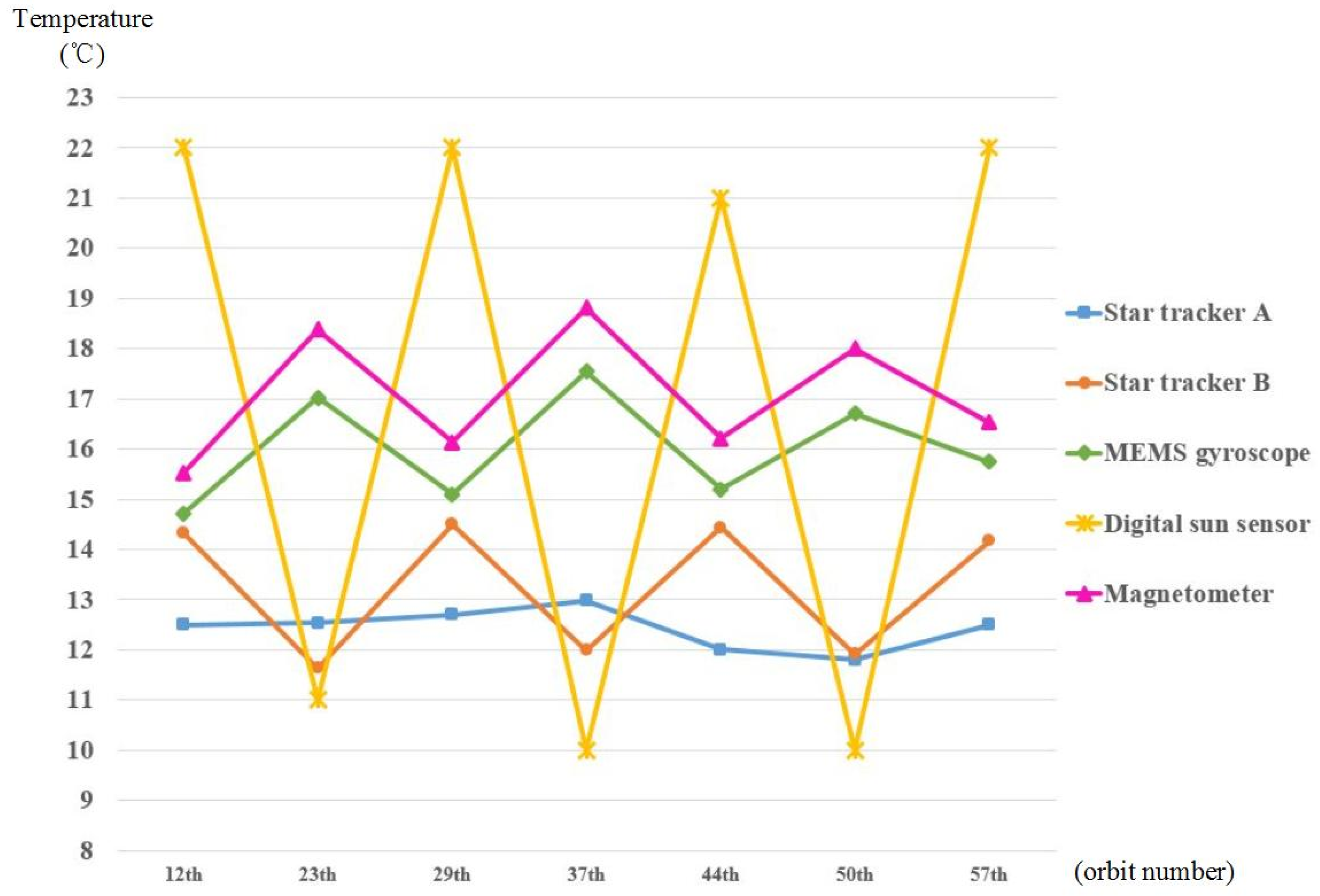
Figure 16.
Temperature variation curve of the outside instruments in the Luojia 1-01.
Figure 16.
Temperature variation curve of the outside instruments in the Luojia 1-01.
Table 1.
Orbit parameters of satellite in general.
Table 1.
Orbit parameters of satellite in general.
| Subjects | Parameters |
|---|
| Orbit height | 645 km |
| Orbit eccentricity | 0 |
| Orbit inclination | 98.04˚ |
| Orbit period | 5855.15 sec |
| Local time of descending node | 10:30 am |
Table 2.
Flight mode and attitude of the satellite orbit.
Table 2.
Flight mode and attitude of the satellite orbit.
| Flight Mode | Attitude | Working Mode |
|---|
| Sun pointing | -OZ axis points to the Sun, -OY axis points to the orbit normal, OX axis is defined by the right-hand rule | Long-term |
| Nadir pointing | -OZ axis points to the Earth, -OY axis points to the orbit normal, OX axis is defined by the right-hand rule | Short-term |
Table 3.
Material properties of the thermal subsystem.
Table 3.
Material properties of the thermal subsystem.
| Materials | Thermo-Optical Properties | Thermal Conductivity |
|---|
| Aluminum coated polyimide film (one side) | | —— |
| Argentum coated F46 film (one side) | | —— |
| 2A12 (black coated) | | 121 W·m−1K−1 |
| 2A12 (Natural aluminum anodized) | | 121 W·m−1K−1 |
| ZT4 (black coated) | | 8.8 W·m−1K−1 |
| T700 (black painted) | | 5 W·m−1K−1 |
Table 4.
Thermal contact conductance coefficient between elements.
Table 4.
Thermal contact conductance coefficient between elements.
| Subjects | Contacting Form | Thermal Contact Conductance Coefficient |
|---|
| Camera and satellite platform | Point contact/rough interface | 10 W/(m2·K) |
| Battery and satellite platform | Point contact/rough interface | 10 W/(m2·K) |
| Antenna stand and satellite platform | Point contact/rough interface | 10 W/(m2·K) |
| Structures and structures | Surface contact/smooth interface | 100 W/(m2·K) |
| Instruments and platform | Surface contact/smooth interface/heat conductivity grease | 1000 W/(m2·K) |
Table 5.
Equivalent thermal conductivity of MLI and heat conduction materials.
Table 5.
Equivalent thermal conductivity of MLI and heat conduction materials.
| Subjects | Equivalent Thermal Conductivity |
|---|
| MLI (20 units) | 0.04 W/(m·K) |
| MLI (10 units) | 0.048 W/(m·K) |
| Heat conductivity grease | 3 W/(m·K) |
| Heat conductivity membrane (horizontal direction) | 1000 W/(m·K) |
Table 6.
Parameters of TCS design requirements in general.
Table 6.
Parameters of TCS design requirements in general.
| Subjects | Parameters |
|---|
| Temperature inside the cabin | −10~+45 °C |
| Temperature of the battery | 10~+30 °C |
| Temperature of star trackers | −30~+30 °C |
| Temperature of camera body | 0~+30 °C |
| Temperature of solar panel | −85~+135 °C |
| Temperature of antennas | −90~+90 °C |
| Mass allocated to thermal control | ≤1 kg |
| Power allocated to thermal control | ≤2 W |
Table 7.
Average heat flux density (W/m2).
Table 7.
Average heat flux density (W/m2).
| Surface | December Solstice | June Solstice |
|---|
| Sun | Albedo | Infrared | Sum | Sun | Albedo | Infrared | Sum |
|---|
| +X | 0 | 37.8 | 76.2 | 114.0 | 0 | 34.5 | 76.1 | 110.6 |
| −X | 0 | 37.8 | 76.0 | 113.8 | 0 | 34.4 | 76.1 | 110.5 |
| +Y | 0 | 46.2 | 49.4 | 95.6 | 0 | 46.8 | 52.2 | 99.0 |
| −Y | 0 | 20.2 | 43.3 | 63.5 | 0 | 14.8 | 44.1 | 58.9 |
| +Z | 0 | 77.1 | 72.1 | 149.2 | 0 | 64.1 | 69.1 | 133.2 |
| −Z | 891.5 | 5.3 | 74.6 | 971.4 | 859.3 | 5.4 | 72.9 | 937.6 |
Table 8.
Regions and instruments of Luojia 1-01 covered by MLI.
Table 8.
Regions and instruments of Luojia 1-01 covered by MLI.
| Regions and Instruments | Amount of Layers |
|---|
| −X panel, ±Y panel, ±Z panel | 20 |
| Internal surface of +X panel | 20 |
| Baffle of the camera | 20 |
| Camera and its bracket | 20 |
| Battery (except the mounting suface) | 20 |
| Star trackers and its brackets (2) | 20 |
| Brackets of the GPS Antennas (3) | 20 |
| Bracket of the digital sun sensor | 20 |
Table 9.
Description of instruments mounting surfaces using heat insulated pads.
Table 9.
Description of instruments mounting surfaces using heat insulated pads.
| Subject | Material of Heat Insulated Pads |
|---|
| Mounting surface between camera bracket and −X panel | Polyimide |
| Mounting surface between baffle and camera | Polyimide |
| Mounting surface between camera and focal plane unit | Titanium alloy |
| Mounting surface between battery and −Y panel | Polyimide |
| Mounting surface between brackets of star trackers (2) and −X panel | Polyimide |
| Mounting surface between GPS brackets (3) and −X panel | Polyimide |
| Mounting surface between digital Sun sensor bracket and −X panel | Polyimide |
| Mounting surface between data transmission antenna and +Z panel | Polyimide |
| Mounting surface between TT&C antenna and +Z panel | Polyimide |
| Mounting surface between side −Z solar panel and −Z panel | Polyimide |
Table 10.
Description of regions and method of thermal conductivity applied in Luojia 1-01.
Table 10.
Description of regions and method of thermal conductivity applied in Luojia 1-01.
| Subject | Heat Conductivity Method |
|---|
| Mounting surface among ±Y and ±Z panels | Heat conductivity grease in contact surface and stickup of heat conductivity membrane |
| Mounting surface between OBDH and −Z panel | Heat conductivity grease in contact surface and stickup of heat conductivity membrane |
| Mounting surface between navigation unit and −Y panel | Heat conductivity grease in contact surface and stickup of heat conductivity membrane |
| Mounting surface between reaction wheels and +Y panel | Heat conductivity grease in contact surface and stickup of heat conductivity membrane |
| Mounting surface between MEMS gyroscope and −X panel | Heat conductivity grease in contact surface and stickup of heat conductivity membrane |
| Mounting surface between magnetometer and −X panel | Heat conductivity grease in contact surface and stickup of heat conductivity membrane |
| Mounting surface between star trackers and brackets | Stickup of heat conductivity membrane |
| Mounting surface between −Z panel and internal surface of the +X panel | Stickup of heat conductivity membrane |
Table 11.
Parameters of the heating regions of the Luojia 1-01 satellite.
Table 11.
Parameters of the heating regions of the Luojia 1-01 satellite.
| No. | Subject | Location | Temperature Threshold (°C) | Nominal Power Consumption (W) |
|---|
| 1 | Heating region of the camera | Tube of the camera | 11.5~12.5 | 2 |
| 2 | Backup for the heating region of camera | Tube of the camera | 9.5~10.5 | 2 |
| 3 | Heating region of the battery | Shell of the battery | 18.0~20.0 | 2 |
| 4 | Backup for the heating region of the battery | Shell of the battery | 15.0~17.0 | 2 |
| | Sum | 8 |
Table 12.
Analysis result of the temperature variation conditions of instruments inside and outside the satellite cabin.
Table 12.
Analysis result of the temperature variation conditions of instruments inside and outside the satellite cabin.
| Location | Instrument | Condition I (°C) | Condition II (°C) | Required Temp (°C) |
|---|
| Inside the satellite | OBDH | 19.1~23.4 | 10.2~15.3 | −10~45 |
| Reaction wheel I | 21.0~27.2 | 12.7~16.6 | −10~45 |
| Reaction wheel II | 14.0~17.5 | 8.2~12.1 | −10~45 |
| Navigation unit | 22.4~28.0 | 13.5~17.8 | −10~45 |
| Signal processing unit | 18.8~20.9 | 9.5~14.4 | −10~45 |
| Outside the satellite | MEMS gyroscope | 16.8~18.3 | 10.2~11.3 | −10~45 |
| Magnetometer | 10.1~12.6 | 5.7~7.9 | −10~45 |
| Star tracker A | 14.8~16.2 | 6.7~9.2 | −30~30 |
| Star tracker B | 15.5~17.4 | 9.7~12.1 | −30~30 |
Table 13.
Temperatures of the onboard instruments in thermal balance test.
Table 13.
Temperatures of the onboard instruments in thermal balance test.
| No. | Thermoscope | Subject | High Temp Condition (°C) | Low Temp Condition (°C) |
|---|
| 1 | T1 (Thermistor) | Camera-1 | 12.4 | 11.9 |
| 2 | T2 (Thermistor) | Camera-2 | 13.9 | 10.8 |
| 3 | T3 (Thermistor) | Focal plane unit | 24.9 | 7.7 |
| 4 | T4 (Thermistor) | OBDH | 26.7 | 6.1 |
| 5 | T5 (Thermistor) | Battery-1 | 19.9 | 18.2 |
| 6 | T6 (Thermistor) | Battery-2 | 20.6 | 18.4 |
| 7 | T7 (Thermistor) | Reaction wheel I | 28.0 | 8.3 |
| 8 | T8 (Thermistor) | Star tracker A | 18.4 | −0.5 |
| 9 | T9 (Thermistor) | Star tracker B | 20.3 | 0.3 |
| 10 | TC1 (thermocouple) | Camera holder | 13.5 | 9.0 |
| 11 | TC2 (thermocouple) | Reaction wheel II | 20.7 | 4.3 |
| 12 | TC3 (thermocouple) | Navigation unit | 29.3 | 5.5 |
| 13 | TC4 (thermocouple) | Signal processing unit | 21.4 | 5.2 |
| 14 | TC5 (thermocouple) | Magnetometer | 15.3 | 2.6 |
| 15 | TC6 (thermocouple) | MEMS gyroscope | 20.3 | 7.2 |
Table 14.
The duty cycle and power consumption of the heating regions.
Table 14.
The duty cycle and power consumption of the heating regions.
| No. | Subject | Heating Circuit | Assigned Power (W) | Duty Cycle | Actual Power Consumption (W) |
|---|
| High Temp | Low Temp | High Temp | Low Temp |
|---|
| 1 | Camera-1 | H1 | 2 | 0.34 | 0.70 | 0.68 | 1.4 |
| 2 | Camera-2 | H2 | 2 | 0 | 0 | 0 | 0 |
| 3 | Battery-1 | H5 | 2 | 0.30 | 0.66 | 0.60 | 1.32 |
| 4 | Battery-2 | H6 | 2 | 0 | 0 | 0 | 0 |
| sum | 1.28 | 2.72 |
Table 15.
Temperature of instruments from on-orbit, ground thermal balanced test and thermal analysis.
Table 15.
Temperature of instruments from on-orbit, ground thermal balanced test and thermal analysis.
| Subject | On-orbit Balanced Temp (°C) | High Temp in Test (°C) | Low Temp in Test (°C) | High Temp in Thermal Analysis (°C) | Low Temp in Thermal Analysis (°C) |
|---|
| Camera-1 | 12.20 | 12.4 | 11.9 | 12.8 | 11.3 |
| Camera-2 | 12.94 | 13.9 | 10.8 | 14.0 | 12.0 |
| Focal plane unit | 18.65 | 24.9 | 7.7 | 24.8 | 7.4 |
| OBDH | 20.54 | 26.7 | 6.1 | 23.4 | 10.2 |
| Battery-1 | 18.63 | 19.9 | 18.2 | 20.7 | 18.6 |
| Battery-2 | 18.68 | 20.6 | 18.4 | 21.2 | 18.0 |
| Reaction wheel I | 20.22 | 28.0 | 8.3 | 27.2 | 15.0 |
| Star tracker A | 12.72 | 18.4 | -0.5 | 14.2 | 6.7 |
| Star tracker B | 13.11 | 20.3 | 0.3 | 17.4 | 9.7 |
Table 16.
Temperature of instruments from on-orbit, ground thermal balanced test and thermal analysis.
Table 16.
Temperature of instruments from on-orbit, ground thermal balanced test and thermal analysis.
| Heating Region | Designed Power Consumption (W) | On-Orbit Power Consumption (W) | Power in High Temp of Test (W) | Power in Low Temp of Test (W) | Power in High Temp of Thermal Analysis (W) | Power in Low Temp of Thermal Analysis (W) |
|---|
| Heating region of the camera | 2 | 0.48 | 0.36 | 1.4 | 0.30 | 1.18 |
| Backup heating region of the camera | 2 | 0 | 0 | 0 | 0 | 0 |
| Heating region of the battery | 2 | 1.20 | 0.86 | 1.32 | 0.78 | 1.34 |
| Backup heating region of the battery | 2 | 0 | 0 | 0 | 0 | 0 |
| sum | 8 | 1.68 | 1.22 | 2.72 | 1.08 | 2.52 |
Table 17.
Amendment comparison of temperature of instruments from in-orbit and thermal analysis.
Table 17.
Amendment comparison of temperature of instruments from in-orbit and thermal analysis.
| Subject | On-orbit Balanced Temp (°C) | High Temp in Thermal Analysis (°C) | Low Temp in Thermal Analysis (°C) |
|---|
| Before | After | Before | After |
|---|
| Camera-1 | 12.20 | 12.8 | 12.5 | 11.3 | 11.9 |
| Camera-2 | 12.94 | 14.0 | 13.2 | 12.0 | 12.5 |
| Focal plane unit | 18.65 | 24.8 | 20.8 | 7.4 | 15.9 |
| OBDH | 20.54 | 23.4 | 22.3 | 10.2 | 18.4 |
| Battery-1 | 18.63 | 20.7 | 19.2 | 18.6 | 18.6 |
| Battery-2 | 18.68 | 21.2 | 19.7 | 18.0 | 18.5 |
| Reaction wheel I | 20.22 | 27.2 | 23.1 | 15.0 | 17.9 |
| Star tracker A | 12.72 | 14.2 | 13.0 | 6.7 | 9.9 |
| Star tracker B | 13.11 | 17.4 | 15.5 | 9.7 | 11.4 |


