The drone is controlled via a 9-channel remote/radio controller (RC) transmitter programmed for three flight modes: altitude hold mode (STD)—altitude hold mode and manual flying using the controller; loiter mode (LTR)—altitude hold mode and automatic positioning using global positioning system (GPS) signal, and mission mode (AUTO)—automatic mode for autonomous missions.
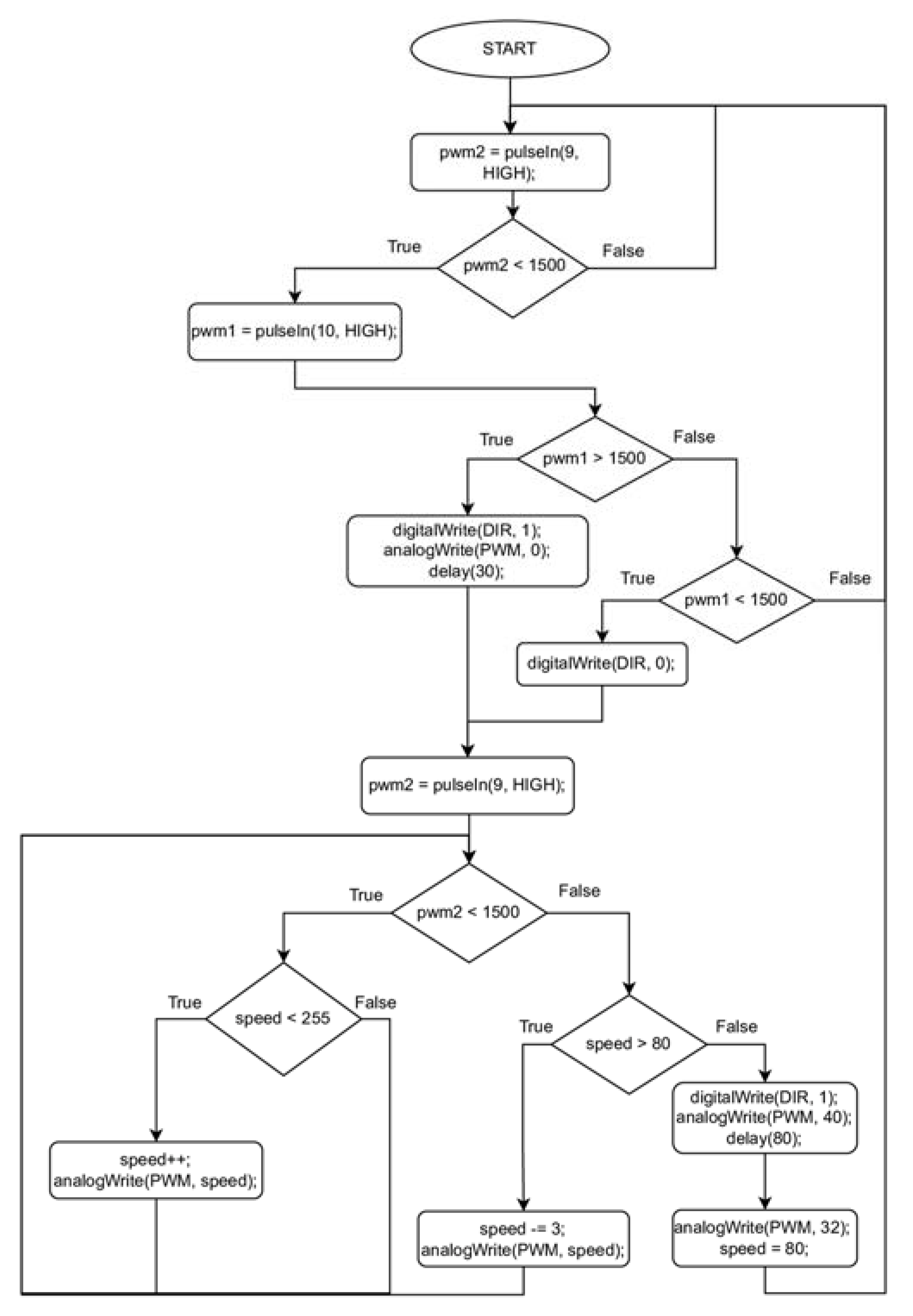
The two transmission channels of the RC transmitter, CH8, and Ch6, control the operation of the device for lowering and lifting the measurement platform by generating the corresponding pulse width modulation (PWM) signal at the output of the aircraft’s flight controller. The CH7 channel settings generate a signal in the range of 991 to 2015 depending on the position of the bi-stable button specifying the downward or upward direction in which the measurement platform is to move. Channel CH8 generates a signal in the range of 992 to 2016 depending on the position of another button, which controls the automatic process of lowering/lifting the measuring platform in a monostable manner. The button released starts an automatic sequence of breaking and finally stopping the direct current (DC) motor which powers the device for lowering and lifting the measuring platform.
With this solution the pilot can control the flight of the drone and the position of the measurement platform at the same time with great precision. This ensures the stable and safe operation of the entire system. For example, the developed solution allows for full control, during a sudden swing of the lowered measuring platform. The pilot can control the distance of the measurement platform from the UAV in real-time, so he can change the force vector causing the swaying of the measurement platform by shortening or unwinding the holding line at the end to which the platform is attached. In extreme cases, the system allows one to correct the position of the drone with the simultaneous lifting of the measurement platform in such a way that the pilot safely docks the swayed element, minimizing the risk of crashing the drone by losing control over it.
The sensing platform is equipped with an independent system and two-way radio frequency (RF) data transmission with a range identical to the RC transmitter controlling the drone. Such a solution makes it possible to control the measurement process and for a user equipped with an RF received connected to a laptop, tablet, or phone to view the collected data in real time. Real-time analysis and communication with the pilot can improve the quality of the acquired measurement data.
2.1. UAV (Drone)
A quadrocopter equipped with 850 kV motors was selected as the drone. It was used to carry a gas-sensing platform and auxiliary equipment to lower and raise the platform. Quadrocopters attracted our attention because of their vertical landing, good maneuverability, high agility, and takeoff capabilities, as well as their simple design, cost-effectiveness, and small size. In our setup, we used a quadcopter from 3DR Iris, 3D Robotics, Berkeley, CA, USA, see
Figure 1. The drone was controlled remotely. Control commands were issued by the operator at a distance of up to 1 km. Pixhawk Flight Controller v2.4.5, 3D Robotics, Berkeley, CA, USA, was used to control the flight. It is a controller designed as "open source", allowing the user to freely configure and modify the drone’s control system. The mission planning system allows for the configuration of autonomous flight along with the operation of peripheral devices without pilot control, in our case a sensor measurement system. The Ublox NEO-7N GPS, U-blox, Thalwil, Switzerland, module was used for flight positioning.
The weight of the drone, including the battery, was 1282 g. The total weight of the measurement system (drone and the measurement equipment including the winch) was 1642 g. The weight of the auxiliary measurement system including the winch did not exceed the lifting capacity limit of 400 g specified by the manufacturer of the 3DR Iris quadcopter. The drone was powered by a 5 Ah 11.1 V lithium-polymer battery, which, according to the manufacturer, should be sufficient for about 16–22 min of flight. During the tests, the maximum flight time was 9 min, leaving about 30–40% of the battery undischarged, depending on weather conditions. The maximum flight speed did not exceed 10 km/h.
During the measurements, the drone was controlled in LTR mode, providing constant altitude and automatic positioning using GPS signals.
To assure adequate space for the measurement system, between the drone body and the ground, a special landing gear was prepared, see
Figure 1. It was made of lightweight and strong fiberglass tubes. They had a length of 215 mm, an inner diameter of 3 mm, and walls of 1 mm thickness. The landing gear was attached to the quadrocopter’s four arms via dedicated adapters made of polyvinyl chloride (PVC).
2.2. Gas Sensing Platform
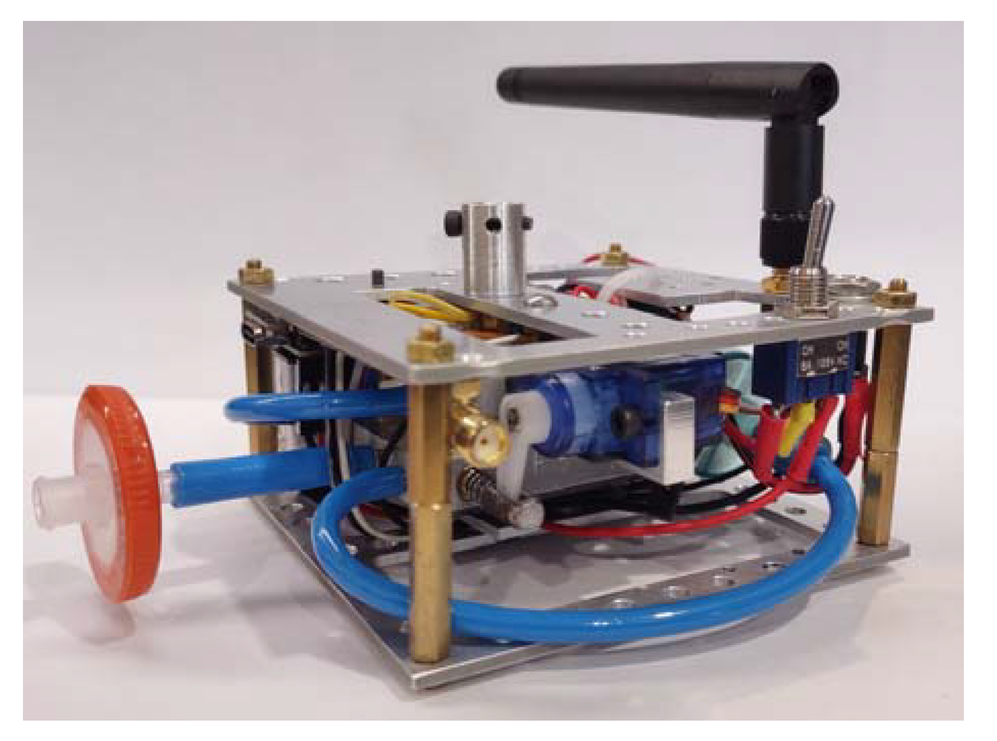
The developed gas sensing platform was dedicated to measuring air pollution. The view of the sensing platform is shown in
Figure 2. It was characterized by a compact design. Its size was 90 mm × 90 mm × 60 mm. The design was compatible with drone size, shape, and mobility. The elements used to build the measurement platform were lightweight, low-cost, and robust to be successful in use. The construction was based on a lightweight, damage-resistant aluminum frame. The weight of the entire sensing unit, including the power supply section and the battery, was 203 g. The sensory platform was equipped with a quick coupler, which allowed the element to be quickly connected to the holding line.
This module was designed to accomplish the following functions: (1) air sampling; (2) conditioning of a test air; (3) generation and measurement of sensor responses to a test gas; (4) signal conditioning; (5) data acquisition and transmission; (6) preparation of reference/cleaning gas, and (7) sensor regeneration. The functions of the gas sensing platform determined its construction. As shown in
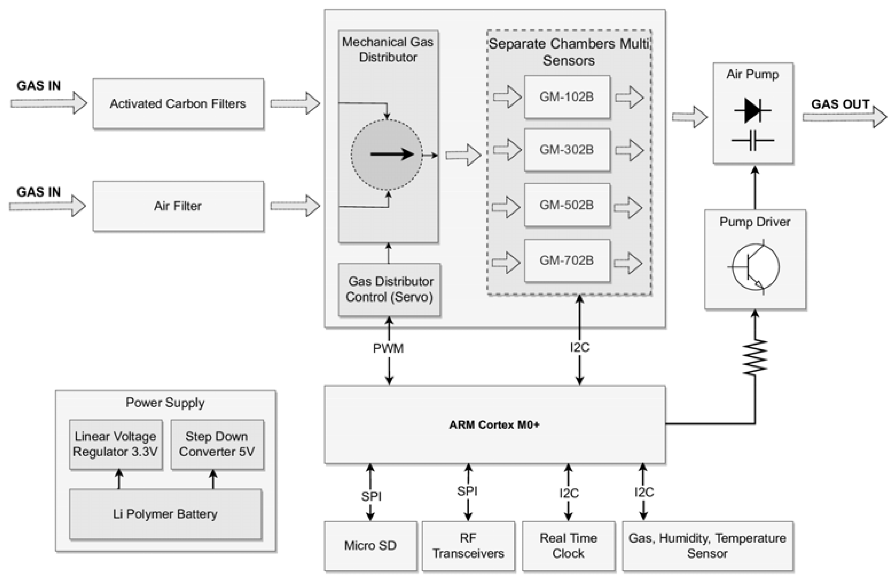
Figure 3, the gas sensing platform consisted of the following components: air intake; two filters; a three-way valve; a measurement chamber with a set of sensors inside; microcontroller; an air extracting pump; a gas transfer line; lithium polymer batteries, and enclosure with a mounting plate.
The specific modular design of the measurement platform made it possible to change the system configuration while maintaining a small size and low weight. All digital devices mounted on the platform were powered by 3.3 V, obtained through linear voltage stabilization of a 7.4 V li-pol battery with a capacity of 700 mAh. A step-down boost converter with an output voltage of 5 V was used to power the air pump and the servo controlling the three-way valve.
The average current consumption was 180 mAh, when the air pump was running at the default level of 66% of its power, while the instantaneous current consumption during data transfer and valve repositioning did not exceed 390 mAh.
All modules of the measurement platform communicated with the microcontroller through digital and analog interfaces. Using the serial peripheral interface (SPI), the microcontroller communicated with the RF module and transmitted real-time data directly to the user over a distance of up to 1 km. In addition, for security, the collected data were stored on a micro secure digital (SD) card on the measurement platform using the SPI bus with a specific chip select (CS) pin assigned to the module. The PWM signal was used to control the position of the three-way valve, managing the gas flow.
The digital-to-analog converter (DAC) output of the microcontroller, via a BC337 transistor, Diotec Semiconductor, Heitersheim, Germany changed the speed of the DC motor the air pump was equipped with, regulating the gas flow through the measurement system.
The Real-Time Clock (RTC) module supplemented any information stored on the micro-SD card with the current date and time. It was equipped with a DS1307 chip, Adafruit Industries, New York, NY, USA and a CR1220 backup battery, Baltrade, Gdansk, Poland. It communicated with the microcontroller via inter-integrated circuit (I2C) protocol buses.
To control the height of the measurement platform, a BME680 multifunctional environmental sensor from Bosch Sensortec, Reutlingen, Germany [
17] was added. It was mounted outside the sensing device. It communicated with the microcontroller using an I2C interface.
The dedicated computer application featured by the graphical user interface (GUI) was developed. It allows full control of the measurement process, data collection, and graphical visualization of measurement data in real time using dynamic line graphs. The application is compatible with Windows.
2.2.1. Air Intake and Gas Filters
The air intake diameter was 4 mm. The device air inlet was connected with two kinds of filters. Air filter 1 consisted of a membrane and it was intended to remove the particulate matter from the air at the intake. Air filter 2 was based on activated carbon and it was intended for the preparation of a cleaning/reference gas. This operation relied on the removal of volatile organic compounds (VOCs). The preparation of the cleaning gas was required for the regeneration of semiconductor gas sensors dedicated to VOCs measurement. Regarding reference gas, the filter was capable of removing VOCs from the air. Therefore, the reference measurement for VOCs sensors could be done in any circumstances, i.e., regardless of the composition of air at the intake. However, air filter 2 was not capable of removing NO2 and CO from the air passing through it. Therefore, the reference measurement for NO2 and CO sensors had to be performed in a location where the air was clean as compared to the air composition at the actual measurement point. During measurement, the test air was directed from intake via air filter 1 to the measurement chamber. During sensor cleaning, for reference measurement, the air was directed through air filter 1 and 2 in sequence, before reaching the measurement chamber. It was assumed that during measurement, air intake was positioned at the level of a measurement point, beyond the air turbulence zone, caused by the drone rotor.
2.2.2. Three-Way Valve
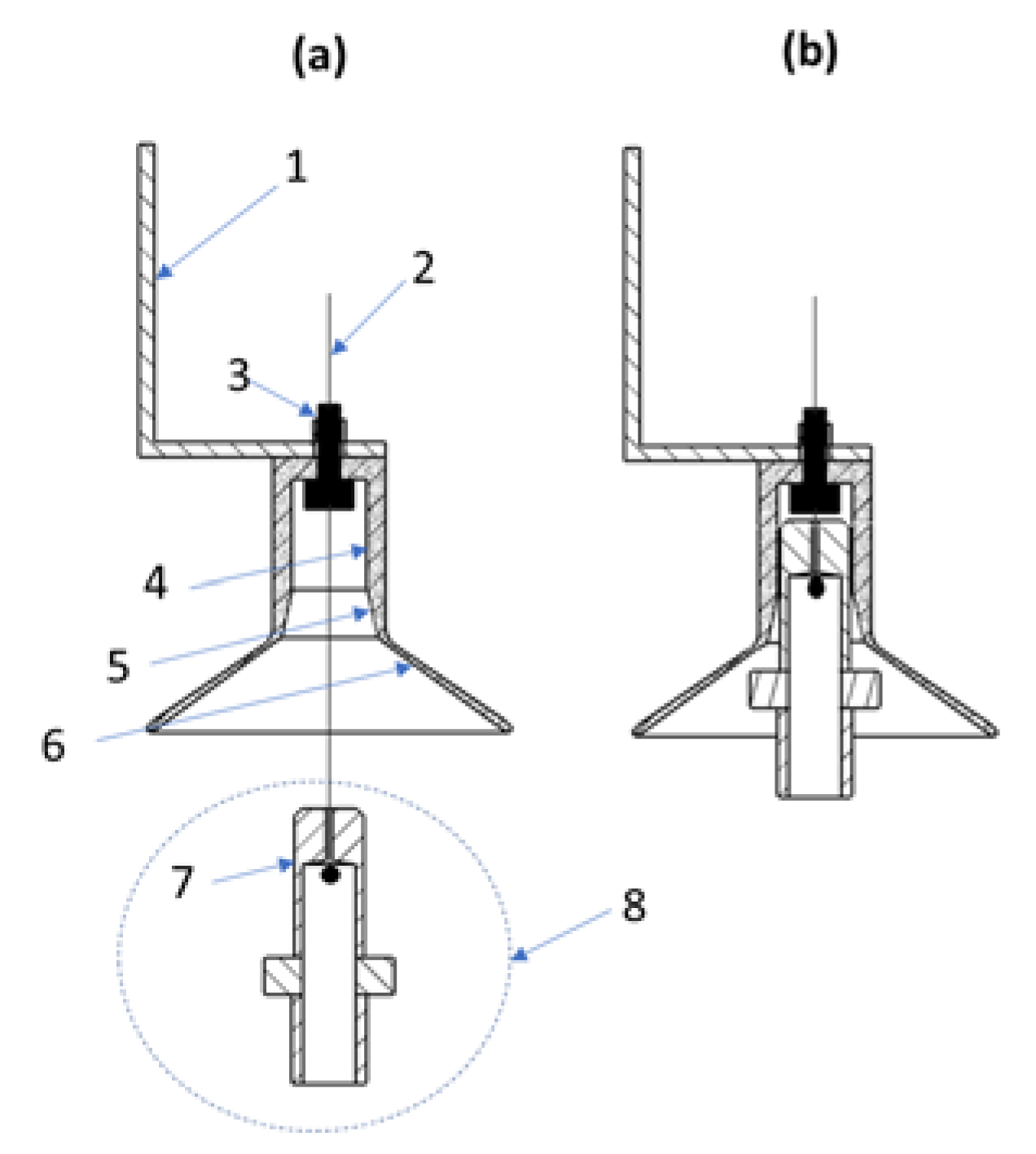
To control the flow of gas through the measuring chamber, a three-way valve was used. It was fixed in the corps of the measurement module next to the sensors chamber, as shown in
Figure 4. The moving element, with a diameter of 3.4 mm and an overall length of 54 mm, was made of hardened steel and moved in a bronze sleeve. The position of the valve was controlled by TowerPro’s SG90 micro servo, TowerPro, Ponte Vedra, FL, USA with a power of 1.8 kg*cm, speed, 0.1 s/60°, and a weight of 9 g. The servo power supply voltage was 5 V.
The fit design ensured smooth operation of the valve while maintaining full tightness of the system. By making special channels in the moving part of the valve, it was possible to control the flow of gas from two different inputs. This allowed the sensors to be exposed to the test gas or the cleaning/reference gas. This solution guaranteed the small size of the pneumatic system and low power consumption. A current of 100 mA was consumed only for a period of 100 ms when changing the valve position. After that, the control servo remained inert and the servo motor control system consumed only 10 mA of current.
2.2.3. Set of Sensors and Measurement Chamber
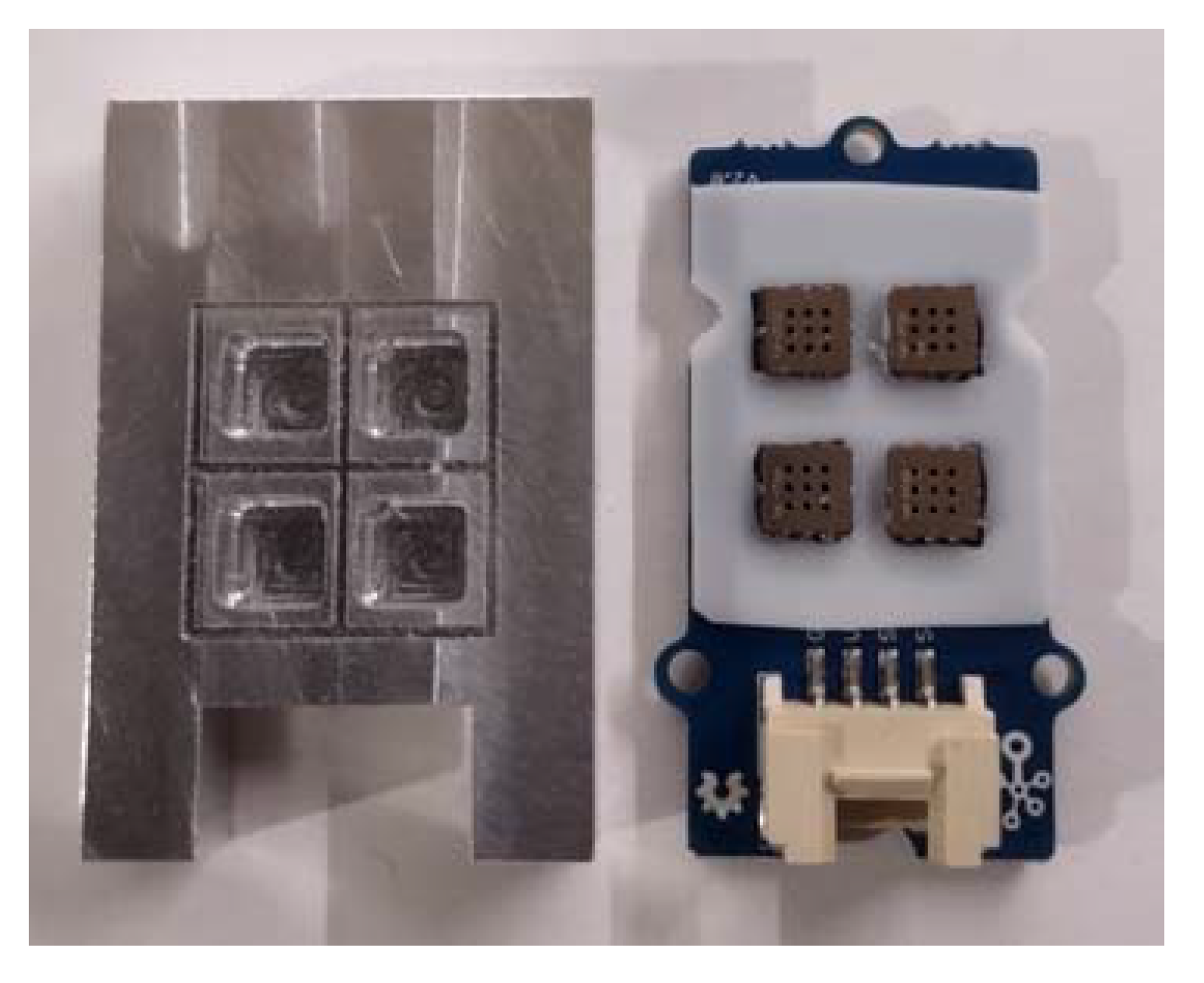
Figure 3 shows the schema of the measurement platform. Its key component was Grove’s 42 × 24 mm four-channel gas sensor module, as shown in
Figure 5 [
18]. It is a compact device equipped with an independent microcontroller TM32F030, Seed Studio, Shenzhen, China which converts analog signals generated by semiconductor sensors into digital form. The sensor module communicated via an I2C interface supported by the microcontroller that controlled the sensor module. It was equipped with four independent semiconductor gas sensors GM-102B (NO2) [
19], GM-302B (ethanol) [
20], GM-502B (ethanol, formaldehyde, toluene, and other volatile organic compounds) [
21], GM-702B (CO) [
22] from Winsen Inc., Zhengzhou, China. They can detect various gases such as carbon monoxide, nitrogen dioxide, ethyl alcohol, volatile organic compounds, etc., but they featured cross-sensitivity. The sensors were manufactured using micro-electro-mechanical systems (MEMS) technology. They are characterized by long life, fast response time, small size, and high sensitivity
The sensor module was equipped with a dedicated Teflon gasket, located between the printed circuit board (PCB) and the measurement chambers, to seal the pneumatic system.
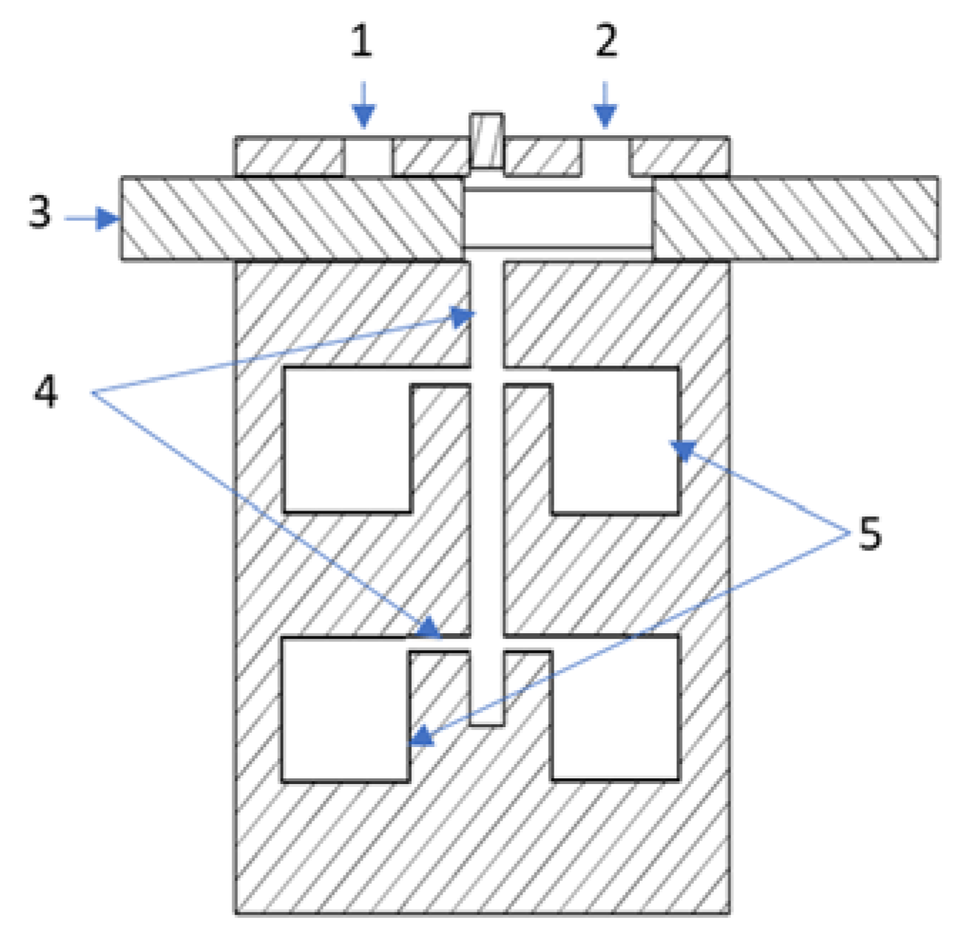
The chambers for the individual sensors were made of solid aluminum along with a built-in miniature three-way valve. It is a compact design in which gas flows through an internal 2 mm diameter channel system connecting the individual chambers to the three-way valve. The gas in the measuring chamber flowed from top to bottom, cutting across along the longest line, as shown in
Figure 6. This organization of gas movement in the sensor cell and the small size of the cell allowed for a quick and complete exchange of the analyzed gas sample. Thanks to this, the device was characterized by a very short response time to changes in the composition of gas sampled by the measuring platform.
Outside the measurement system operating in the dynamic mode, the BME680 environmental sensor was located. The module is a combination of a total volatile organic compounds (TVOC) sensor, temperature sensor, humidity sensor, and barometer. Its primary task in our application was to measure atmospheric pressure for determining the current height of the measuring platform, relative to a reference point. The reference height can be set by the operator, controlling the operation of the measuring platform. During the tests, the height of the measurement platform was counted from the ground, at the drone’s launch site.
The data sampling resolution of all sensors in the measurement system was set at 420 ms.
2.2.4. An Air-Extracting Pump
The gas outlet from the measurement chamber was connected to a miniature air extraction pump, operated via the digital-analog converter (DAC) output of the microcontroller controlling the measurement platform. The pump used the model JSB1015091, weighing 8 g and measuring 8 × 10 × 15 mm equipped with an M20 motor with an operating voltage of 3V–5V DC. The input and output manifolds had an outer diameter of 3.2 mm with a flow diameter of 1 mm. The pump was made with diaphragm technology. It used the reciprocating motion of the diaphragm, generated by a DC motor to allow air to flow using appropriate check valves. A DC motor controller based on a BC337 transistor was used to enable smooth control of the air flowing through the measurement system via the DAC output of the microcontroller.
During testing, the gas flow through the gas sensing module was set to 11 l/h. The pump’s supply voltage was 3.3 V and it consumed 65 mA of current. The pump was attached by an aluminum adapter to a corps including a sensor chamber and a three-way valve.
2.2.5. A Gas Transfer Line
The individual components of a sensing platform were connected by a gas transfer line prepared from tiny polytetrafluoroethylene (PTFE) tubes. The diagram of pneumatic connections is shown in
Figure 3. A gas transfer line allowed the gas sensors to be exposed to the incoming air due to the operation of an air-extracting pump. The gas line was relatively short to avoid water condensation and gas adsorption. Elimination of surface chemistry phenomena during the presence of the gas in the inner tube was especially important in the case of gas sampling for VOCs measurement. For this reason, the system was cleaned with clean air after each measurement. The duration of an individual measurement was several minutes due to the drone flight time limit.
2.2.6. Microcontroller
The gas-sensing platform was equipped with a small Seeeduino Xiao module with a 32-bit SAMD21G18 microcontroller based on the ARM Cortex-M0+ processor, which operates at up to 48 MHz. It features 256 kB of flash memory, 32 kB of static random-access memory (SRAM), and support for digital and analog interfaces. It is powered by 3.3 V and consumes a maximum of 20 mA of current. The module was used to control and manage the operation of the measurement platform, sensors, data acquisition, wireless transmission, and data processing, which were received via I2C buses using addresses and assigned to each device:
SeeedStudio multi-channel gas sensor module (address 0 × 55);
4-in-1 BME680 multifunctional environmental sensor (address 0 × 76);
DS1307 real-time clock (address 0 × 68).
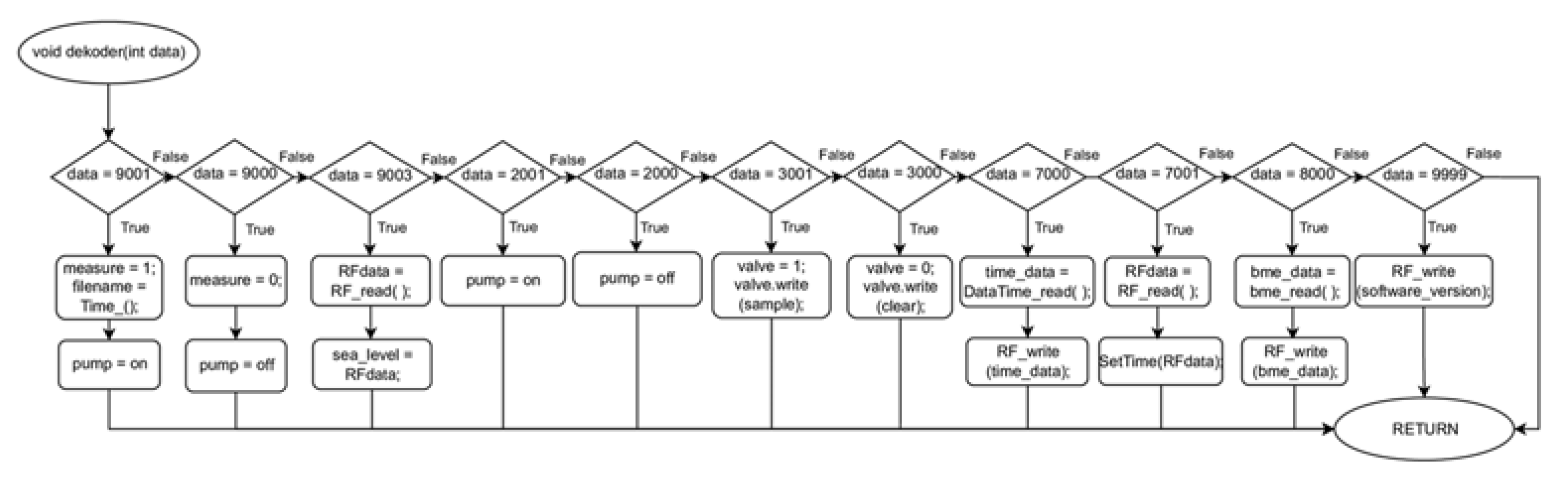
Figure 7 shows the algorithm of the program that managed the operation of the measurement platform. After starting the device, the system configured the operating parameters of all modules on the measurement platform, informing the user via the wireless communication system of the device’s configuration status. The main loop of the algorithm started by checking the register of the RF receiver. When a command was received from the user, the system passed a value of integer type to the function decoder (RFdata.toIn t( )); this is shown in
Figure 8 where the process of interpreting the transmitted information and taking appropriate action takes place:
9001–Change the parameter ‘measure’ (1- measure mode on and start the air pump, assign a value to the ’filename’ variable);
9000–Change the parameter ‘measure’ (0 - measure mode off and stop the air pump);
9003–Change the altitude above sea level, the command sets the altitude to zero at the current position;
2001–air pump on;
2000–air pump off;
3001–change the position of the three-way valve, the valve directs the air under test to the sensors chamber;
3000–changing the position of the three-way valve, the valve directs clean air from the activated carbon filter to the sensors chamber;
7000–sending the current date and time from the RTC module to the user;
7001–configuring the current date and time for the RTC module;
8000–sending the data from the BME680 sensor to the user;
9000–sending information about the current version of the measurement system to the user.
After receiving the 9001 command, the algorithm changed the value of the ‘measure’ register. This initiated the measurement procedure that collects information from the RTC, BME680, and multisensor module. After the data reading procedure was completed, the information from the sensors from the multisensor module, together with the value of the ‘valve’ register and the data from the BME sensor, was sent by radio, via the RF module, to the user. The next step was to save the sent information on the micro-SD card, adding at the end the ‘time–data’ variable specifying the current time and date. The data from each measurement process started and completed were saved in a separate file, the name of which specified the day and time the measurement started. The file name was specified by the ’filename’ variable, which was assigned the value of the current date each time a measurement process was started with the 9001 command.


