1. Introduction
A microgrid is an organic system composed of loads, distributed generations (DGs), and energy storage devices. Relative to the main network, a microgrid is an intelligent controlled unit. For customers, a microgrid can realize self-control, self-protection, and self-management in a flexible manner. It can meet the demands of a variety of load and specific power quality requirements [
1,
2]. In a microgrid, the inverter is one of the most important components. Yet it presents some drawbacks, such as the small output impedance, weak ability of overload, and lack of inertia [
3,
4]. The virtual synchronous generator (VSG) algorithm has been proposed to alleviate the above drawbacks by simulating the inertia element of the synchronous generator. As the extension of droop control, VSG enables it to respond to the abnormal frequency of the grid side and improves the stability of the power system [
5,
6,
7,
8].
Low-voltage microgrid lines present resistive or resistance-inductance properties, which can lead to strong coupling between active and reactive power outputs. This phenomenon may cause considerable impacts on the normal operation of microgrid, grid-connected control, and the power allocation among the DGs. Hence, it is important to investigate the power coupling effect for the improvement of operational stability and economic efficiency of the microgrid [
9].
In engineering practice, large inductance has been introduced to reduce the coupling extent. However, this effort increases the line voltage drop and the total cost. Traditional VSG control has not paid much attention to power decoupling. Research on the independent control between active and reactive powers has mostly been based on droop control. The specific decoupling methods can be divided into three categories. The first one is based on the coordinate transformation. A coordinate rotation matrix can be established according to the impedance angle of the line, and is used to transform the real power flows [
9,
10,
11] into decoupled virtual power flows. Similar results have also been developed to transform the output voltage into decoupled virtual voltage [
12,
13]. This approach can only realize the decoupling of the virtual power output, but not the real power output. Since the equivalent droop equations have been changed, the microgrid cannot be directly accessed by the distribution network that contains the traditional power generation, such as a steam turbine or diesel-driven generator. Moreover, complexity increases for the power control.
The second category is the virtual impedance-based decoupling control [
14,
15,
16,
17,
18]. Through introducing a virtual inductance and subtracting its voltage drop at the input side of the voltage loop, the system impedance can be adjusted for power decoupling. Although this approach is simple, a large virtual inductance is required in the resistive environment, which can aggravate the line voltage drop and causes harmonic pollution.
The inversion of droop control is categorized as the third type [
19,
20]. Traditional droop control contains an active power channel (
P–
f) and a reactive power channel (
Q–
V), which exists strong coupling between the power outputs in the microgrid. Hence, some scholars have proposed the
P–
V and
Q–
f droop control. This creates a good power decoupling effect in the resistive environment. However, it is only appropriate for the case in which the line resistive value is far greater than its inductance value. Moreover, the microgrid cannot be directly accessed by the distribution network that contains the traditional power generation, such as a steam turbine or diesel-driven generator, because the equivalent droop equations have been changed.
All three approaches do not realize the decoupling control by acting on the coupling component directly. Thus, they can be considered as the indirect decoupling method. This paper proposes a power decoupling method, which directly compensates for the coupling component of the power loop. The decoupling is attained by use of a decoupling matrix in the VSG control unit and making the power transfer matrix a diagonal matrix. This method is based on the linearized power transfer model. It possesses a simple structure and better stability compared to the existing decoupling methods. In addition, the proposed power decoupling method is suitable for power decoupling in the microgrid, which has variable loads and frequent small power fluctuations.
The rest of this paper is organized as follows. The principle of the VSG control method is described in
Section 2. The power/frequency and excitation controller are also introduced. In
Section 3, the mechanism of power coupling is studied and the small signal model of the power loop is established. The proposed decoupling method based on the diagonal decoupling matrix for VSG is analyzed in
Section 4. The feasibility analysis and improvement for power sharing are given. Simulation results are presented in
Section 5 to demonstrate the effectiveness of the proposed method, followed by the conclusion in
Section 6.
2. VSG Control Principle
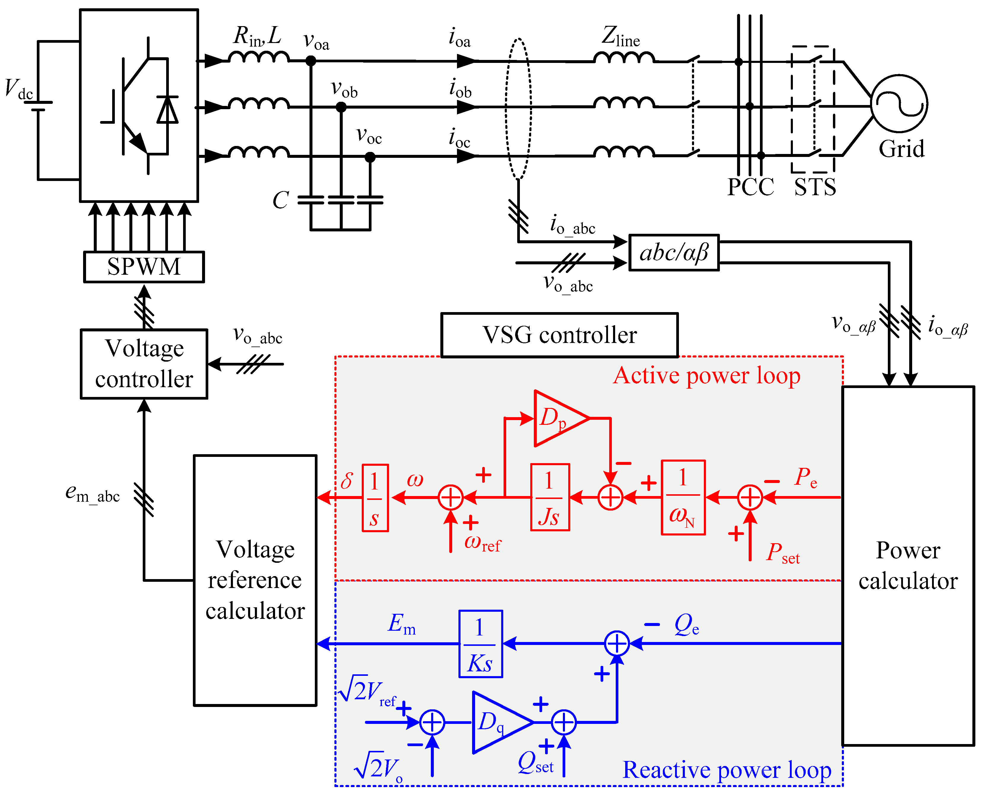
The main structure of one grid-connected inverter using the VSG control strategy is shown in
Figure 1. A distributed generator (DG) with stored energy is located at the direct current (DC) side. For simplicity of analysis, a DC source is used here instead. The three-phase voltage-source inverter is adopted in the main circuit.
Vdc is the voltage of the DC source;
Zline is the line impedance from DG to the point of common coupling (PCC);
Rin,
L, and
C denote the inductance internal resistance, the smoothing inductance, and the smoothing capacitance of the filter, respectively;
vo and
io are the filter capacitor voltage and the inverter’s output current, respectively;
ic denotes the filter capacitor current;
Pset and
Qset represent the input mechanical power and reactive power reference of the inverter, respectively; and
Pe and
Qe represent the active and reactive power output of the inverter, respectively. In this article, according to the instantaneous power theory,
Pe and
Qe can be calculated as:
The outer power loop generates the command voltage, which is used as the input signal of the voltage loop by controlling the instantaneous active and reactive power of the inverter. To ensure the accuracy, the voltage loop adopts the quasi-proportional-resonant (quasi-PR) controller which is characterized by an excellent tracking performance.
Figure 1 also shows block diagrams of the active power loop and the reactive power loop. The active power loop mainly simulates the rotor motion equation of synchronous generator (SG). A second-order model of SGs can be expressed as [
8]:
where
δ is the power angle of the SG
, ω is the electric angular frequency of the SG,
J is the moment of inertia of the SG,
Dp is the damping coefficient representing the function of damping winding,
ωref is the synchronization angular frequency of the power grid, and
ωN is the rated angular frequency. During normal operation, the angular frequency reference
ωref is equal to
ωN, which can implement the primary frequency modulation (PFM) of VSG. For the design of the active power loop of VSG, most existing researches on the design of the VSG active power loop are based on the PFM function.
The reactive power loop of VSG contains the floating voltage and the reactive power controlled unit. Its control operation can be expressed as:
where
Dq is the droop coefficient of voltage,
K is the reactive power regulation coefficient, and
Vo and
Vref are effective values of the output voltage and rated voltage, respectively. The input command signal
em of the voltage loop can be obtained by combining the amplitude information
Em generated by the reactive power loop and the phase information
δ by the active power loop as:
3. Output Power Model of Microgrid
To facilitate the analysis and ensure the generality, the simplified equivalent circuit of a micro-source is illustrated in
Figure 2.
In
Figure 2, the micro-source is equivalent to a controlled voltage source.
S =
P +
jQ is the line power of the microgrid.
e is the output voltage of the micro-source and
v is the voltage of PCC. The phasor form can be written as
E∠
δ and
V∠
0. The grid impedance is represented by
Z, which consists of the output impedance
Zout and the line impedance
Zline. Suppose that the grid impedance is referred to as
Z∠
θ =
R +
jX. A single phase study is given below. The output power equation can be written as:
In a high-voltage or mid-voltage power grid, the line impedance is generally considered to be inductive (
θ = 90°) because the impedance due to line inductance is much larger than that due to line resistance. Moreover, the phase angle difference
δ is normally under 30° for a synchronous generator and in this case, sin
δ ≈
δ and cos
δ ≈ 1. Then, (5) can be simplified as:
Consequently, the active power can be regulated by adjusting the phase angle δ and the reactive power can be regulated by adjusting the amplitude of the inverter output voltage, which is the basis of the droop characteristics of VSG. However, in the low-voltage microgrid, there is large resistance in the connecting line. The approximate decoupling cannot be obtained and strong coupling exists between active and reactive power controls. In this paper, to solve this problem, the linearized model of output power is established first.
The output power deviation matrix caused by the respective deviations
and
at the quiescent point (
Es,
δs) can be expressed as:
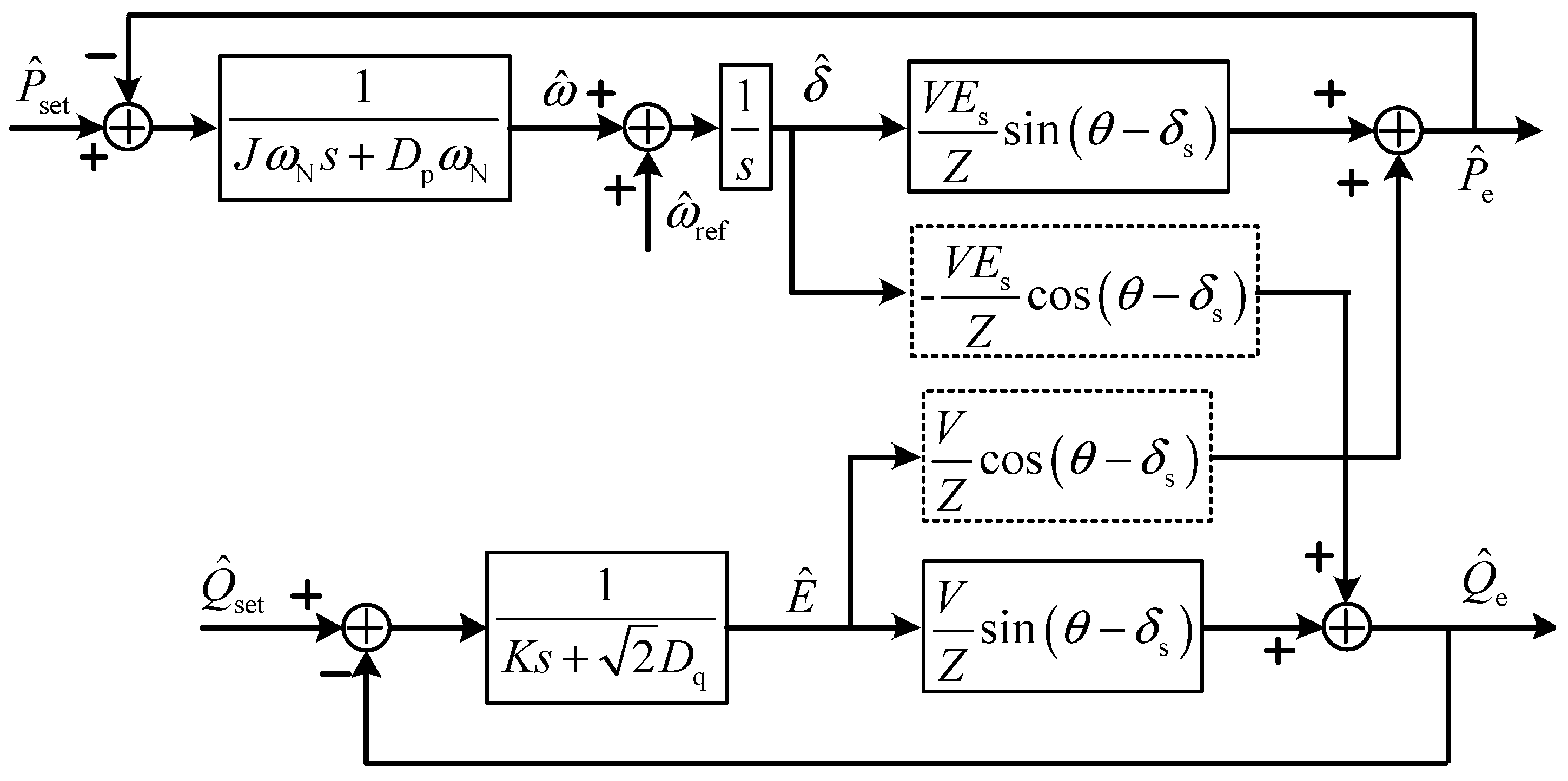
Equation (7) represents the output power model and the associated 2 × 2 matrix is called the power transfer matrix (PTM). Then, the small-signal VSG control structure of the power loop can be derived from (2), (3), and (7) and is illustrated in
Figure 3. The power coupling components in the dashed boxes can be observed clearly. When the impedance angle
θ decrease, the coupling components between the active and reactive power will increase. Moreover, the coupling component between the active power and the voltage amplitude is much smaller than that between the reactive power and the angular frequency.
4. Decoupling Control Method for VSG Control
This paper intends to compensate for the coupling component by adopting a direct power decoupling method. Direct decoupling control methods have two popular types: dynamic decoupling and static decoupling. Dynamic decoupling requires that the channels are decoupled in the transition process and in the steady-state process. This method deeply relies on the mathematical model of the system and cannot attain the desired effect if the model experiences errors or parameter perturbation. Static decoupling only requires the channels to be decoupled in the steady-state process. Although it may degrade the decoupling performance and incurs dynamic deviation, it has a lower sensitivity to model error and parameter perturbation. Thus, this paper adopts the static decoupling method.
4.1. Control Principle
A feed-forward decoupling compensator for a two-input and two-output (TITO) system was introduced to obtain the approximate decoupling [
21]. However, the influences on the original coupling channel in series with the compensator are not considered. This may change the proportional gain of the original channel and affect the stability of the power control loop. In the previous section, the power independent control can be realized when the PTM is a diagonal matrix. Borrowing from this thought and the modern control theory, a diagonal decoupling matrix is introduced.
It follows from (6) and
Figure 3 that the coupling channels of the output power can be regarded as a TITO system. Inputs are
and
and outputs are
and
in the complex frequency domain. Static decoupling requires that the transfer function matrix be a nonsingular diagonal constant matrix. The PTM of Equation (7) can be expressed as:
The decoupled transfer matrix can be expressed as a diagonal matrix
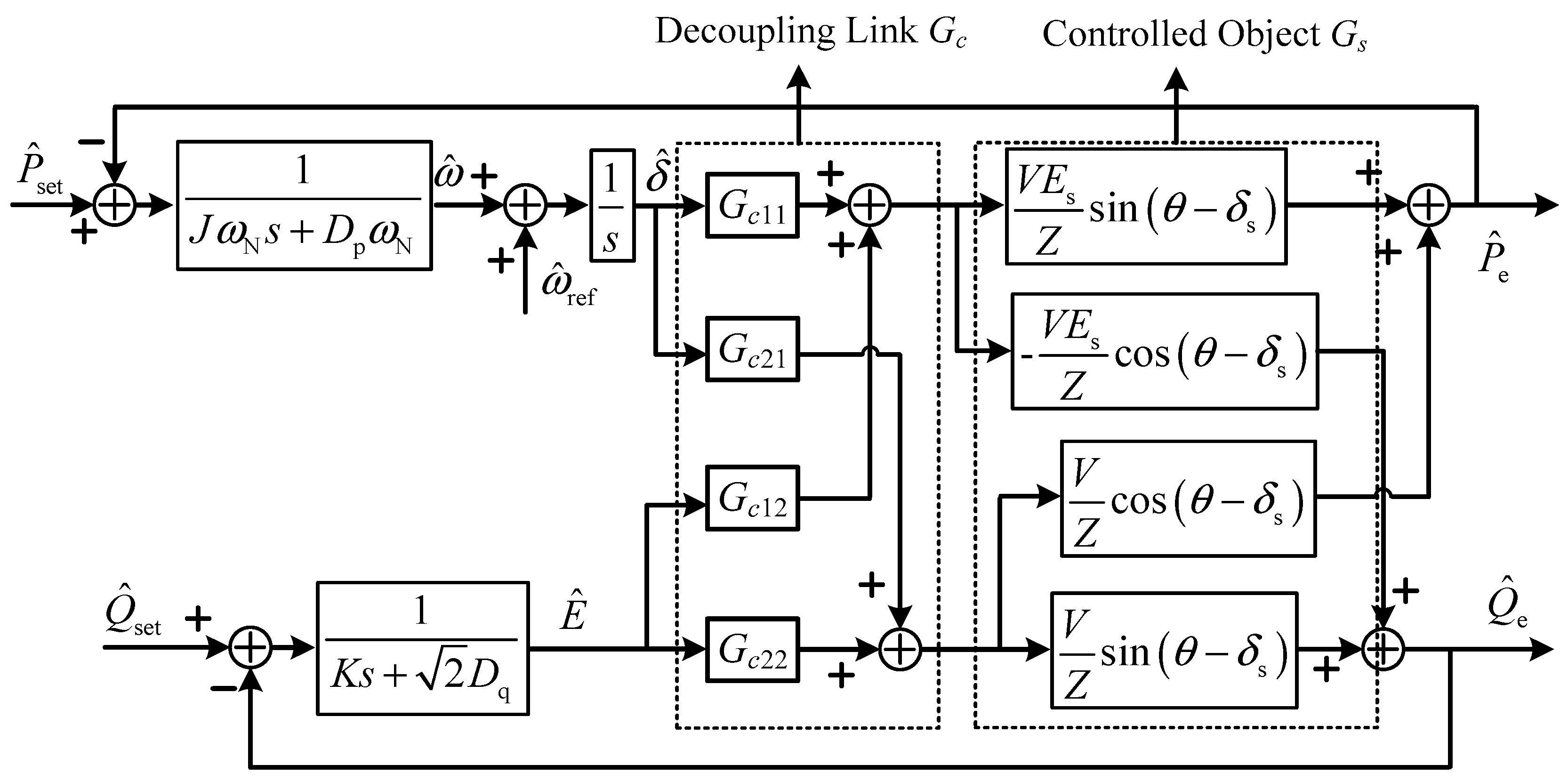
Then, the transfer function of controlled object in series with the decoupling link
Gc becomes
It is observed from (11) that only the impedance angle is needed and the definite length of the distributed line is not required. This method is based on compensating for the coupling component.
Figure 4 shows the control diagram of the power loop in series with the decoupling link.
4.2. Feasibility Analysis and Improvement Approach for Power Sharing
A diagonal compensated matrix has been introduced to attain power decoupling based on the quiescent operating point. According to the relative gain array (RGA) method of the decoupling control [
21], the RGA of the
Gc can be derived as:
From (12), the coefficients of RGA always vary in (0, 1), which means that the introduction of the decoupling link cannot affect the stability of the system. On the other hand, since (7) denotes the average values of the instantaneous power flows over half the fundamental frequency cycle, discussions can only reflect the characteristics of the system in the frequency range that is lower than two times the power frequency. The decoupling method based on the diagonal matrix is only applicable to the power regulation under small disturbance near the quiescent operating point. If the output voltage amplitude and power angle change over a wide range, the decoupling effect of the system may be reduced and it is necessary to dynamically adjust the coefficient of power decoupling link. Otherwise, the decoupling may be a failure. Nonetheless, due to its simple structure and better stability, this method is suitable for power decoupling in a microgrid which has a diversity of loads and frequent small power fluctuations.
The other issue considered by power decoupling control is power sharing. To guarantee the sharing of actual power, improved virtual power-based control with a unified rotation angle is proposed [
9]. Because the transformation matrix is nonsingular, the actual power will be shared equally as long as the virtual power is evenly shared among parallel inverters. Although the limitation of the actual power sharing performance heavily relies on the consistence of line impedance angles of the inverters is overcome, when the transmission lines among parallel inverters are different, the power decoupling effect will still be diminished.
Introduction of the decoupling link does not change the gain of the original channel. When the system reaches the steady state, a simplified equation can be derived:
Equation (13) describes the droop characteristic between the active power and frequency of VSG. The active power sharing can be achieved directly by making
Dp of each inverter proportional to its capacity. For
Q–
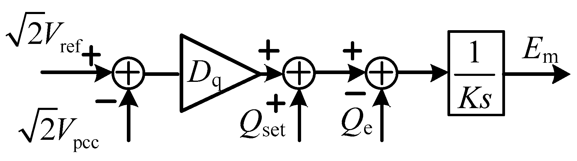
V control, however, the output voltage of the inverter will be not same due to the existence of line voltage drop. This phenomenon affects the reactive power sharing. To overcome this problem, the PCC voltage is introduced as a consistent variable.
Figure 5 shows the improved reactive power loop. The reactive power sharing can be ensured by making
Dq of each inverter proportional to its capacity.


