1. Introduction
Discrepancies in cell internal resistance and differences in cell capacity are common among cells connected in series. Cell inconsistencies might lead to cell overcharging and overdischarging. Without an effective balancing mechanism in the battery management system (BMS), the lifetime of battery modules could be prematurely shortened and this could lead to catastrophic disasters [
1,
2]. The BMS is therefore imperative for active or passive balance circuits to overcome the inconsistency problems among serially connected cells.
Passive balancing methods and active balancing methods are two frequently adopted types of balance method. In passive methods, low power resistors are used to shunt charging currents to overcome the inconsistency among cells in series [
3,
4,
5]. Due to the severe limitation of power ratings, passive methods are slow and inefficient. If fast balance is needed, high resistors with high heat generation are required with passive methods. High heat generation in the BMS necessitates costly heat dissipation mechanisms within the BMS. With passive methods, if the inconsistency level is high among cells, overcharging is unavoidable in practice. Overcharging has a negative effect on cell lifespan, so if possible, any level of overcharging should be avoided. Overall passive methods have low efficiency and are not suitable for large storage capacity applications.
Active balance methods equalize inconsistencies among cells in series by moving electrical energy from higher state of charge (SOC) cells to lower SOC cells. References [
5,
6,
7,
8] used small capacitors and inductors as storage medium to actively transfer electrons between neighboring cells. However, usually the capacitors or inductors adopted in active balance schemes are small and the resulting balance currents are small. Texas Instruments Inc. (Dallas, TX, USA) developed a PowerPump™ balance IC which used two MOSFETs and capacitors to pump charges between neighboring cells to equalize cell inconsistencies with a balance current of less than 200 mA [
9].
By moving electrons between cells with high efficiency active balance methods are intrinsically more efficient than passive balance methods. However, when electrical energy is transferred between cells that are not in the immediate neighborhood, active methods could be inefficient. Existing active balance methods work best for small numbers of cells in series. One more drawback of active methods is the frequency of exchanging electrical energy is too high in most active methods. High frequency of charging or discharging in lithium ion cells could accelerate the cell degradation rate. If the active balance scheme is not well planned, over discharging might result from cells with high levels of inconsistency.
Lin [
10] adopted a global type active balance method with a large balance current to improve the shortcomings of local type active balance methods.
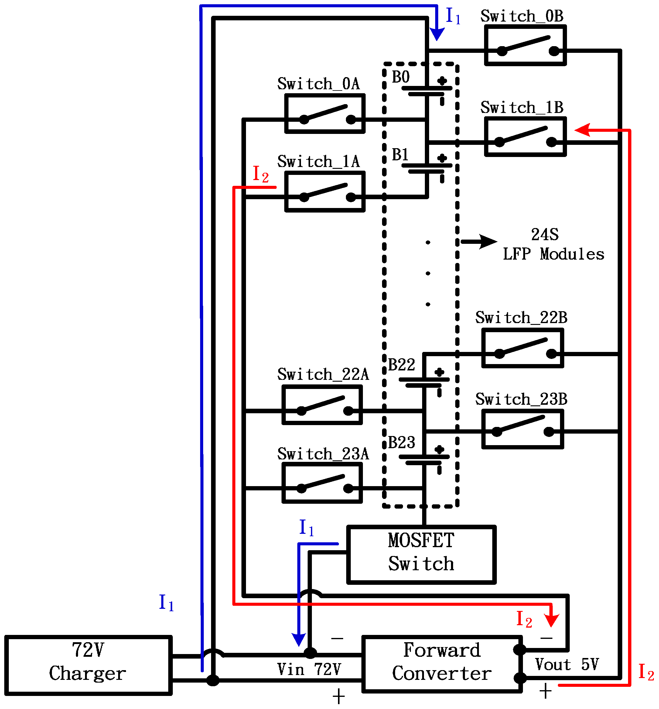
Figure 1 is a schematic of a globally active balance circuit. In
Figure 1, the power source of the balance block is the 72 V charger and the balance block is regulated by a forward converter with a 5 V output. The balance current can be large if the power rating of the forward converter is large too. A forward converter module FEWS-6005.5B30 made by Danube (Kaohsiung, Taiwan) [
11] is adopted in the current study.
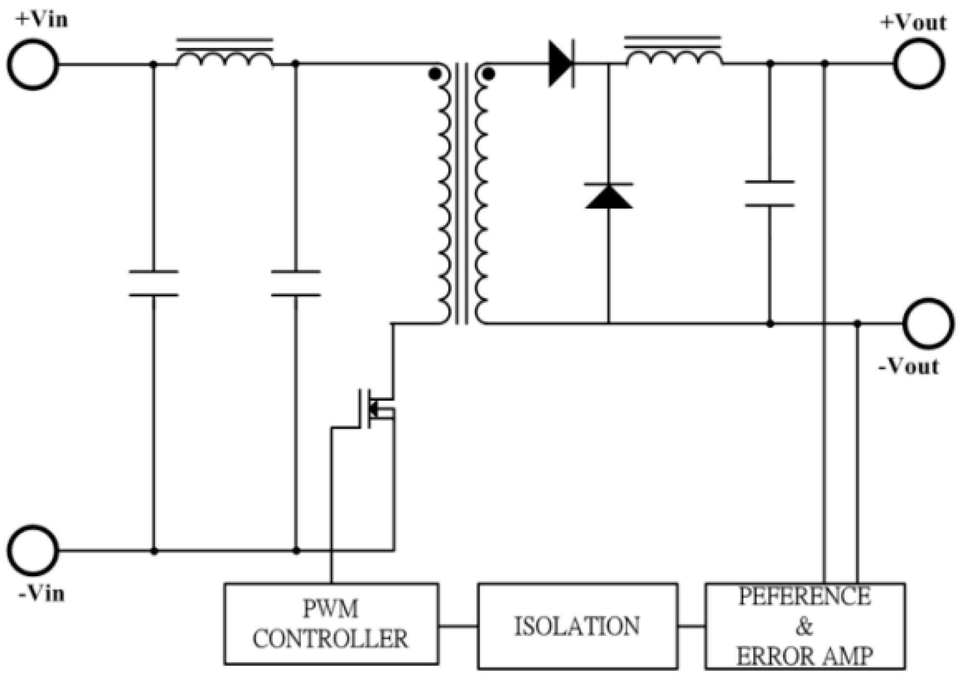
Figure 2 is the circuit of the adopted forward converter. In the forward converter circuit of
Figure 2, a transformer is used for voltage reduction and circuit isolation. This converter balances weak cells with a 6 A balance current with rated 85% efficiency. In
Figure 1, any weak cell is selected by two opto coupling type relays in the relay matrix. Since any cell in
Figure 1 can be selected to be balanced by the forward converter, this balance method is therefore a global type. This global type balance circuit selects the weak cell and transfers external energy until equalization among cells is reached. The MOSFET switch in
Figure 1 is used to cut off charging process when any cell is overcharged. Six NXP BUL956R1-100E N-MOSFETs (NXP Semiconductors N.V., Eindhoven, The Netherlands) [
12] in parallel are adopted along with a RCD snubber to suppress voltage spikes while switching on and off. The schematic of the MOSFET switch is shown in
Figure 3. The developed gloabal type balance circuit has the advantages of larger balance current, shorter balance time, and higher efficiency.
Table 1 compares the characteristics of the various balance methods.
Conventionally, balance circuits are built inside the BMS. However, balance circuits with large balance currents will occupy about 50% of the BMS PCB area and demand active heat dissipation. From in-house experience and commercial case observation, balance modules with large balance currents inside the BMS require roughly the same amounts of electronic components to construct as the rest of the BMS circuits. Therefore, the weight and space of the BMS PCB without balance module is roughly 50% of the original BMS PCB with balance module in the same PCB. In order to simplify the BMS inside the battery module, this study redesigns the structure of the BMS by separating the balance circuit from the BMS and integrating the balance module with a charger. In the charger end, problems associated with heat dissipation, space, and complexity for the BMS with built-in balance module can be easily resolved since off board charger has no space limitation and has a built in fan for cooling. In the following method section, a two-staged charging and balancing method facilitated by a globally active balance module for the current study is explained. The new BMS is tested on an electrical motorcycle and experimental results are detailed in
Section 3. Finally, conclusions are drawn in the last section.
3. Experiments and Results
A 72 V electric heavy motorcycle as shown in
Figure 8 was designed and fabricated in the current study to test the performance of the developed BMS. The current study utilizes the developed global type active balance method [
10] in developing a 72 V BMS. This 72 V BMS is controlled by an 8-bit PIC18F87K22 MCU. This BMS possesses accurate measurement of cell voltages and practical estimation of battery SOC. Data acquisition circuits were built in the main control subsystem to simplify testing. The accuracy of the self-made acquisition system is thoroughly tested and compares with calibrated high accurate instruments. Accuracies of measured parameters, voltages, currents and speeds, are all within 1% of respective full scale.
The test platform in
Figure 8 is composed of one complete electric motorcycle with a rear hub motor of 72 V, a 72 V/60 Ah recycled LFP battery module, the main control subsystem electrically connected with the battery module, a battery charger of 72 V, and an independent balance module in the charger end. When charging the battery module with the two staged charging method, the balance module is electrically connected to the main control system by 25 wires as balance conduits and RS-485 wire for communication between the main control subsystem and balance module. An electrically isolated RS-485 IC is adopted to avoid electromagnetic interferences.
Recycled LFP battery cells are adopted in the current study to demonstrate the unique feature of the developed balance method. The adopted LFP battery cells have a wide spread of characteristics. Cell capacity varies from 9 Ah to 12 Ah and internal resistance varies from 1.5 mΩ to 4.5 mΩ. For a 60 Ah module, six cells are connected in parallel and the average internal resistance for each module is about 0.5 mΩ. The wide variation of the LFP modules in series poses great challenges for any BMS’s balance capability. This study attempts to charge each module fully without overcharging any module in series.
3.1. Tests of a Two Stage Charging Method
Tests of the two stage charging method developed by the current study were conducted in the test platform of
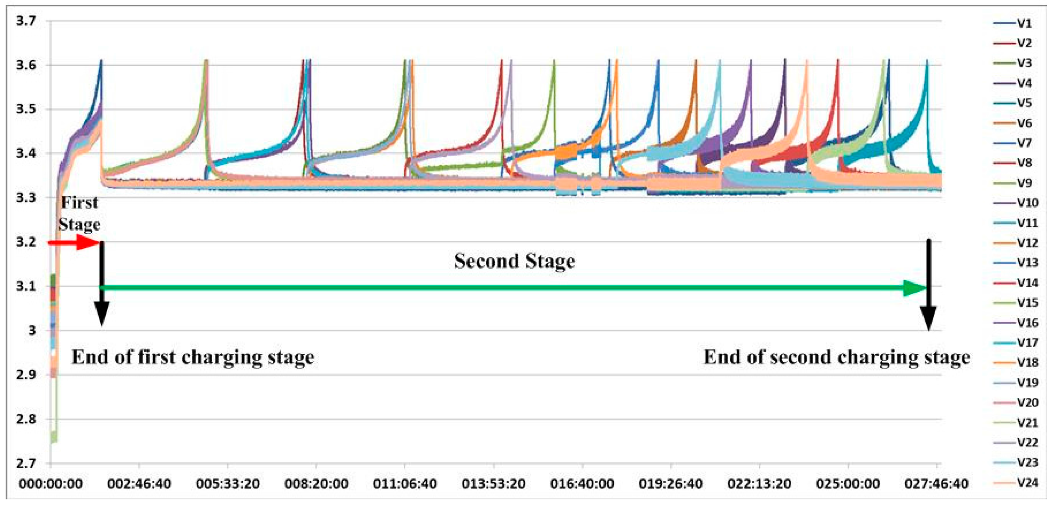
Figure 8. The charging process is monitored by a LabView-based HMI developed for this study. The results are presented in
Figure 9, where real-time values of 24 cell voltages during the charging process are plotted versus charging time in seconds. Initially, the maximum cell voltage difference of the battery is 360 mV before charging. In the first stage, after every cell reaches a predetermined overcharged voltage, first stage charging ends and second stage charging begins. In
Figure 9, twenty four peaks near 3.6 V characterize the completion of the second stage and the whole charging process. The voltage difference among the 24 cells stays smaller than 20 mV a few minutes after the whole charging process ends as indicated in
Figure 9.
3.2. Discharging Tests
The discharging tests were conducted on the 72 V heavy electrical motorcycle shown in
Figure 8. Battery and vehicle operation parameters were extracted by the main control subsystem and recorded at 1 second intervals in the built-in SD card for post-processing.
Figure 10,
Figure 11,
Figure 12 and
Figure 13 are the results for a typical test drive of the e-motorcycle over a regular road in Taiwan.
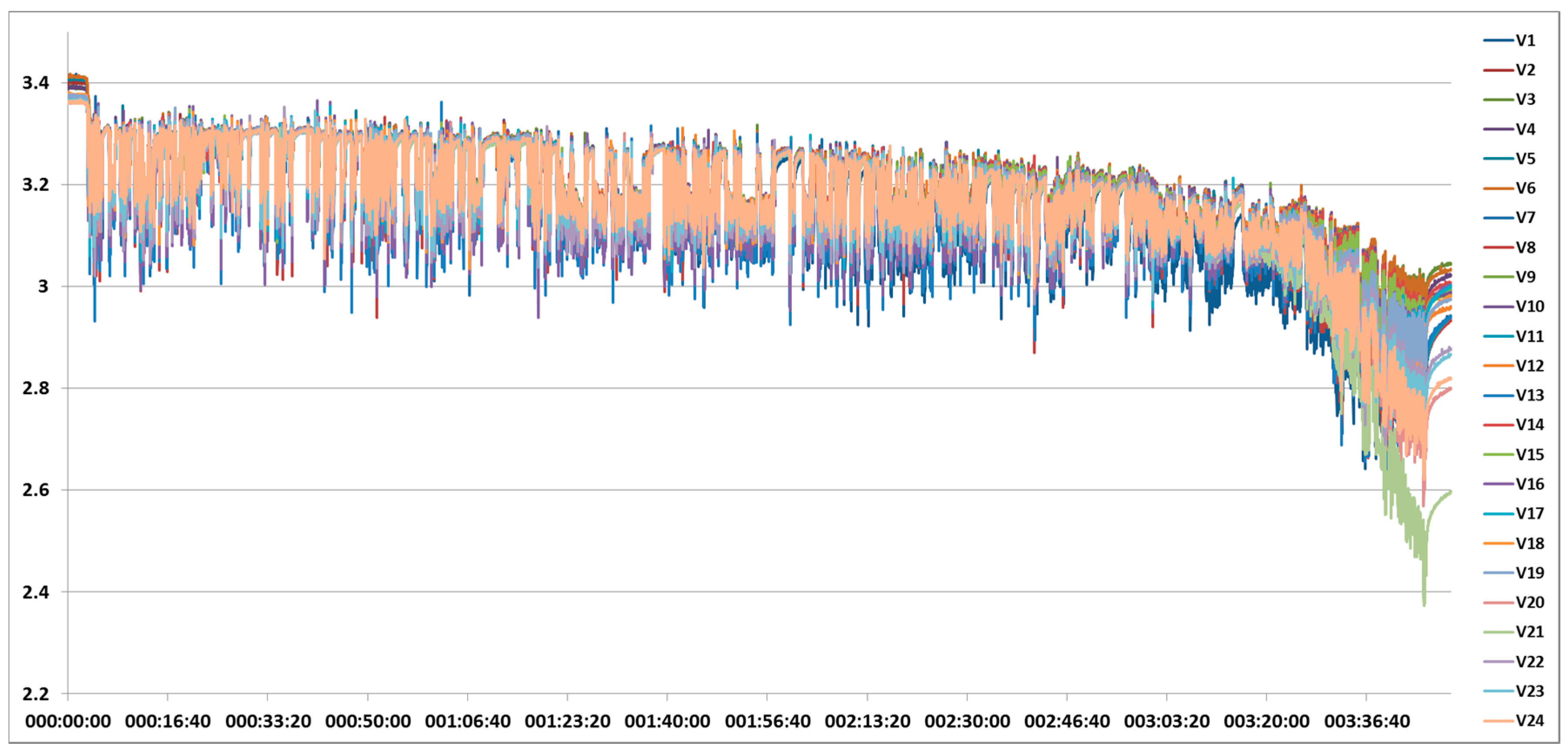
Figure 10 is the cell voltage discharging history. Initially the maximum cell voltage difference among the 24 cells was about 20 mV and at the end the voltage difference was more than 530 mV as shown in
Figure 10.
Figure 11 shows the voltage and current histories for the main battery. The complete trip takes about 3 h and 47 min before undervoltage is approached. The average power consumption of the hub wheel motor is about 3.9 kW, obtained from multiplying the battery voltage and current and taking average over the complete trip.
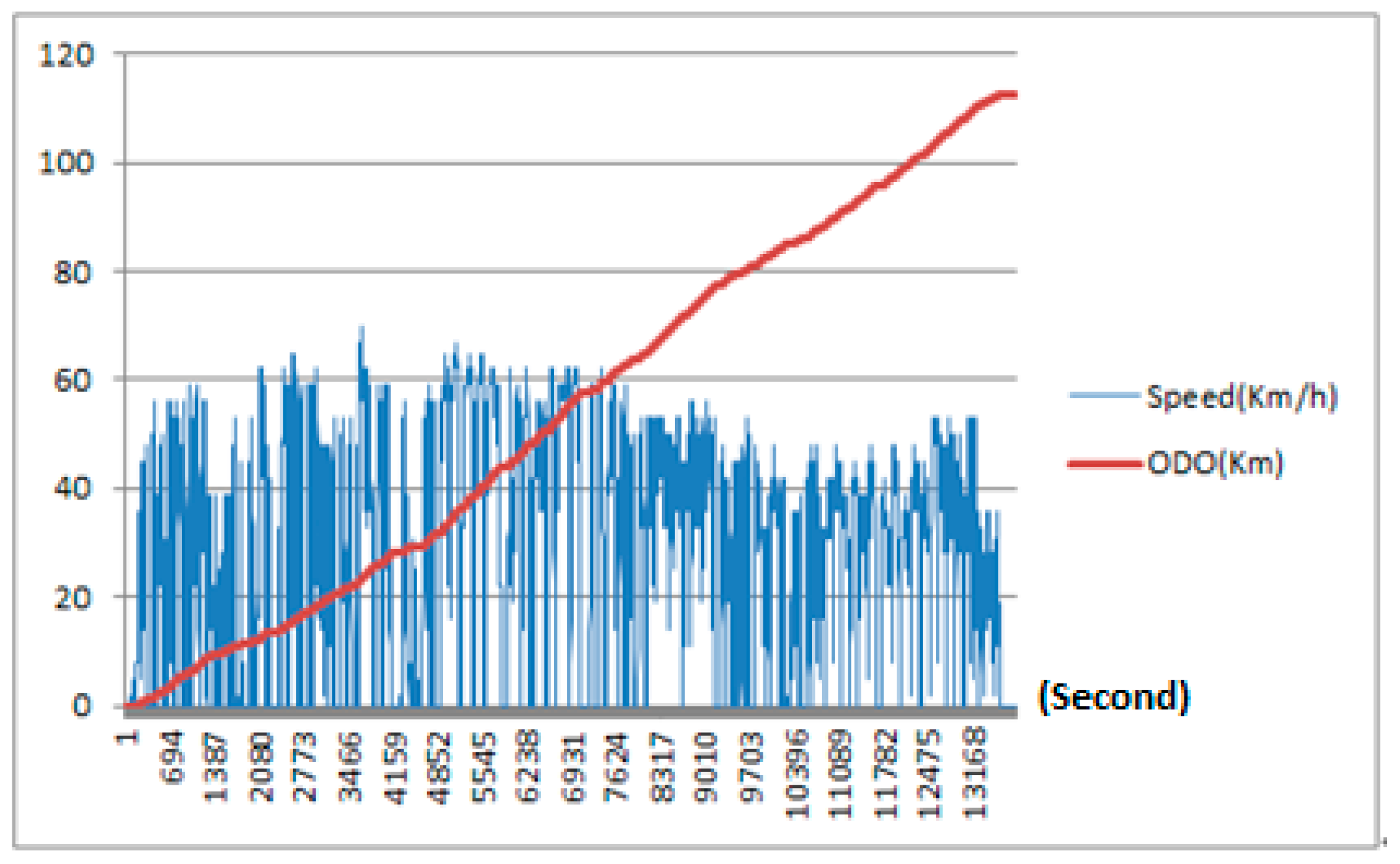
Figure 12 shows vehicle speed and accumulated mileage histories for the trip. Average speed of the trip is about 40 km/h and the total mileage of the trip was 111.2 km.
Figure 13 presents the battery voltage, accumulated mileage, and SOC histories. The initial SOC after two-staged charging is 100%. After driving or discharging for 3 h and 27 min, the SOC drops from 13.5% to 10%.
The abrupt change of SOC is implemented by the hybrid SOC estimation method adopted by the current study. Since the condition of switching from a Coulomb counting method to an EMF correlation method is met, SOC is switched according to the EMF value at that transition point. This hybrid SOC method is therefore capable of adapting to cell inconsistencies or cell aging. Calibration of the cell capacity fade is also allowed in such structure. A detailed description on the developed hybrid SOC method is under preparation for publication.
3.3. Range Extension Benefits of Two-Staged Charging and Balancing Method
The second stage of the developed method can fully charge every cell and could have range extension benefits. Charging tests with the second stage and without the second stage are conducted, respectively, discharging with the same 72 V e-motorcycle platform. Test results are summarized in
Table 2, where the first two tests charge the main battery without the second stage and the battery only accepts 45.1 Ah and 43.7 Ah, both close to 70% of the battery’s full capacity. The driving ranges for these two cases are 86.4 kM and 85.59 kM, respectively.
The third test in
Table 2 adopts second stage charging and 60 Ah is injected into the main battery. The driving range of this case is 114.2 kM and 57.9 Ah is discharged before the low voltage is reached. Close to 28 kM of driving range is gained if the complete two-staged charging is implemented. In other words, the developed two staged charging method has range extension benefits.
It is noticed in the first two tests of
Table 2 that the cell voltage inconsistency or difference deteriorated if the second stage of charging is not implemented. If the second stage of charging is implemented, the cell voltage inconsistency could be improved as shown in the third case of
Table 2. Since cell voltage inconsistency greatly affects battery efficiency, two staged charging is therefore capable of enhancing battery efficiency by reducing voltage inconsistency.


