1. Introduction
Nowadays, power quality is a topic of great importance to all consumers. Industrial, commercial and residential electricity consumers have non-linear loads or loads that are sensitive to disturbances in the electricity supply. This scenario requires a higher level of non-interruptable power quality, therefore drawing even more attention to this topic. The main motivation of this paper lies in the possibility of improving the quality of electric power supply. Presently, occurrences that affect the power quality are considered to be an issue to these loads sensitive to parameter variations of the grid [
1,
2].
In this context, this paper focuses on the development of an alternative synchronous compensator with a different control strategy, using as a generator a doubly-fed induction machine (i.e., power flowing both through the stator and through the rotor), and with the aid of two power converters in the back-to-back configuration, thus characterizing a Doubly-Fed Induction Generator (DFIG). The main objective is to improve the power quality, by developing of strategies capable of compensating active and reactive power in scenarios where the system experiences voltage and current imbalances.
Problems related to voltage control and stability are not new in the electric power industry around of the world, as noted in [
3]. As such, there are many papers from different decades published targeting these topics.
In recent years, there is a notable concern with the rules proposed by grid codes of several countries related to the low-voltage ride through (LVRT). This is reflected in the number of publications tackling this issue, with the most varied proposals of methods to adapt the power systems to the new grid codes.
One of the factors that incite the weakening of the power grid is related to impedance increase at certain locations, thus making the system vulnerable to all sorts of imbalances and distortions. The impedance is, in turn, related to the inability of the system to control the reactive power required [
4].
The proposed synchronous compensator utilizes the kinetic energy stored in the machine rotor to help stabilize the system’s power during short faults or rapid load fluctuations. It is able to provide reactive and active power without oscillations in scenarios where there is imbalance between the phase voltages. Imbalances in the grid current are also investigated.
As Ref. [
5] points out, the kinetic energy storage in the rotor is the basic principle of flywheels. There are numerous studies in the literature that apply this principle for reactive power compensation. In this line, Nishio et al. [
6] developed a flywheel fed by a power converter, generating up to 30 kVA and providing active and reactive power to the system during voltage sags. Highlighting the limitation of conventional static compensators such as the Static Var Compensator (SVC), which only provides reactive power compensation, Akagi and Sato [
7] presented a compensator capable of controlling not only reactive but also active power, based on the energy stored in its flywheel. In turn, Molinas et al. [
8] proposed the application of a flywheel to stabilize voltage imbalance in power stations during transients. Similarly, Weissbach et al. [
9] used a flywheel to restore balanced voltage sags. They compared the compensation efficiency between series and parallel connection. To achieve this, a synchronous motor is used in its compensator. In [
10], the authors explored the use of a synchronous generator as a compensator to analyze the system stability by control of both reactive and active power. In Ref. [
11] mathematical models are applied to compensate current imbalances, known as Steinmetz method. This compensation method uses symmetric components in the frequency domain. The compensation current values were obtained from the estimated susceptance of each branch of the compensator. The same compensation model was later adapted to the time domain so that it could have an instantaneous compensation. The work in [
12] presents some types of loads that compromise the stability of the system. The authors presented some definitions, consequences, losses and techniques applied to reduce unbalanced currents. In [
13], the authors proposed a different method for compensation of current imbalances by applying the instantaneous power theory, better known as the
pq theory. Akagi aimed to promote the balance of the system by eliminating undesirable power (oscillating terms) that are present in the power system. This compensation method is valid for both transient and steady state scenarios, and including for general waveforms of voltage and current.
The use of asynchronous machines in a compensator is also not new in the literature. There are many works with this theme, however each one with its particularities. Of all compensators utilizing wound rotor induction machines, Uemura et al. [
14] mentioned the need for a large amount of active power transfer due to the electricity consumption behavior. They proposed a generator based on flywheel aimed at the stabilization of the power system and also providing reactive compensation to the one. Molinas et al. [
8] investigated the use of a flywheel with wound rotor induction machine in scenarios with voltage transients. The authors in [
15] studied a flywheel to provide quality and reliability to the grid. To provide reactive power, it uses a squirrel-cage induction machine (which at times functions as both a motor and a generator) and two PWM(Pulse Width Modulation)-controlled inverters. Methods to compensate harmonic currents due to the presence of non-linear loads in the system are studied in [
16]. This paper compares the performance of the compensator, initially with a squirrel cage motor and later with a wound rotor induction motor. Already operating the induction machine as DFIG, the authors in [
17] noted that, by storing kinetic energy in the rotating part of the DFIG, it is possible to controlling active and reactive power. The authors also proposed a new strategy for the DFIG operating as compensator, by combining vector control and decoupling control. The authors in [
18] explored the possibility of decoupling the speed control machine from the grid frequency, in the case of a variable speed synchronous compensator based on wound rotor induction machine. The methods and results of more recent papers [
19,
20,
21,
22,
23] are compared with those obtained in this article in the
Section 4.3.
It is noteworthy that, in this literature review, no publication that specifically addresses a study of the DFIG in the molds proposed by this work was found. None of the materials researched in the literature propose to develop a compensator specifically aimed at providing non-oscillating active and reactive powers, even when the grid presents imbalances caused by single-phase voltage sag, for instance.
This paper intends to study and bring light to this very specific knowledge gap that exists in this area of power quality. The intention is to investigate the technical feasibility of such equipment, paving the way for further analysis, such as financial feasibility.
2. Mathematical Modeling
The rotor side converter (RSC) controls the active and reactive power of the machine stator. Usually, the method employed is the field-oriented control (FOC). This customary modeling considers positive sequence voltage components only.
The vector control in
dq synchronous reference frame (SRF) employs the stator magnetic flux vector as reference. When this vector is aligned with the SRF axes, the control variables become DC values, allowing the regulation with proportional integral (PI) controllers and ensuring that the steady state error is reduced to zero. The stator currents in SRF, and simplified for a fifth-order model in steady state condition, in the Laplace domain, are given by [
24]:
where
,
,
, and
are, respectively, the stator and rotor currents in the direct and quadrature axis (frequency domain);
is the stator voltage in the quadrature axis (frequency domain);
is the magnetizing inductance;
is the inductance in the stator windings; and
is the frequency of the stator voltage. As mentioned previously, the RSC is used to control the stator active and reactive power in DFIG systems. The stator active power (
) is defined by:
where
,
,
, and
are, respectively, the stator voltage and current in direct and quadrature axes. Since the stator magnetic flux vector is aligned with the SRF d-axis, which leads
to zero, the stator active power can be reduced to:
Taking into account the previous simplifications and substituting Equation (
2) into Equation (
4), one can find:
where
is the rotor current in the quadrature axis. From Equation (
5), it is possible note that, by controlling the q-axis rotor current component, and as long as the grid voltage is constant, the stator active power can controlled through
.
The same method can be employed for the d-axis, this time controlling the stator reactive power and aiming at regulating the voltage at the point of common coupling.
The stator reactive power (
) is defined by:
Considering that the stator flux modulus in direct axis (
) can be calculated according to the following expression:
Equation (
1) can be rewritten as:
where
is the rotor current in the direct axis. Substituting Equation (
8) into Equation (
6), and taking into account that the term
is zero, the following expression is obtained:
In steady state, the electromagnetic torque (
) can be written as:
where
p is number of poles pairs.
2.1. Positive and Negative Sequence Components Estimation
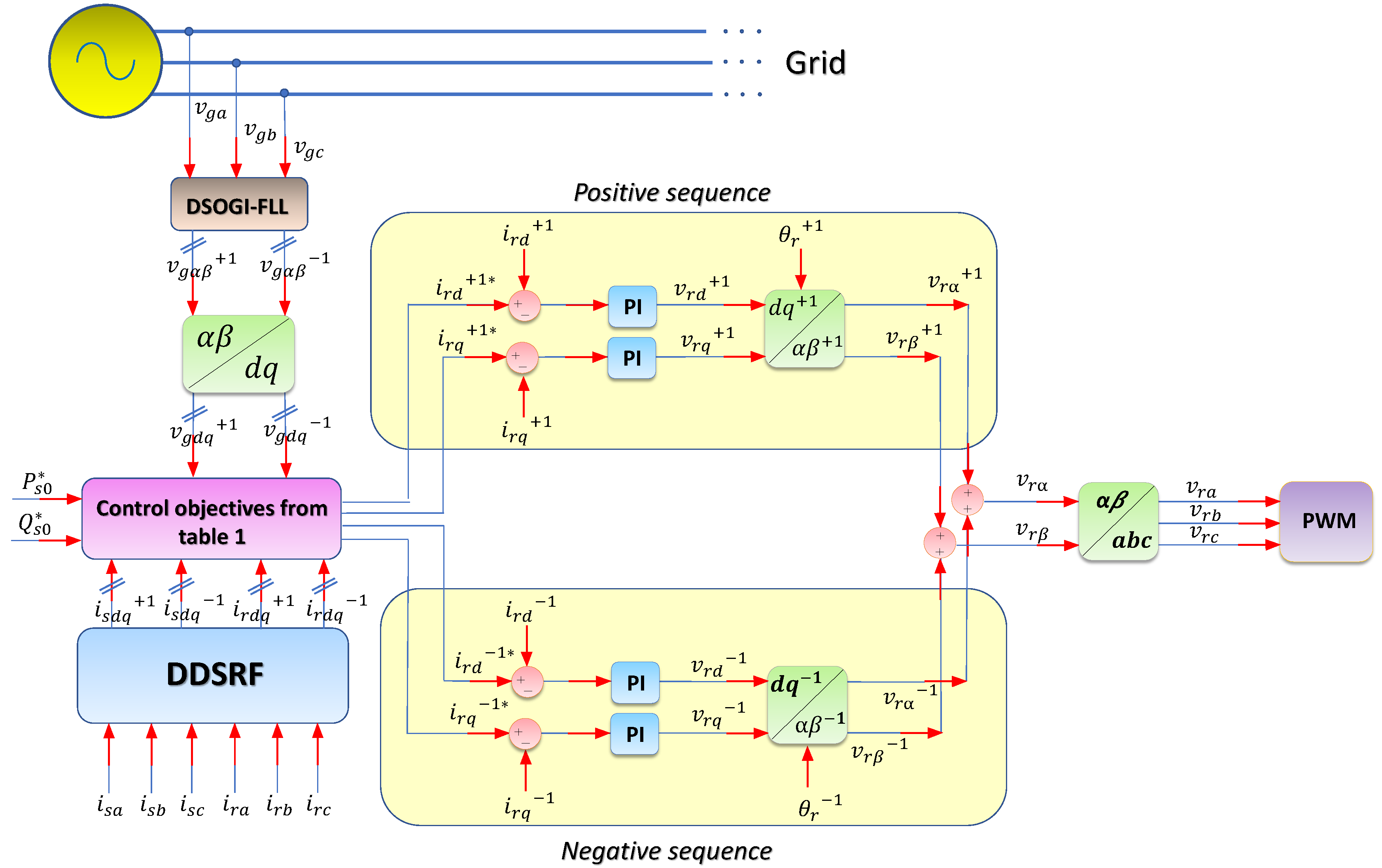
This paper uses the Decoupled Double Synchronous Reference Frame (DDSRF) method, presented in [
25], that allows decoupling the effect of the negative sequence voltage components on the positive SRF and the positive sequence voltage components on the negative SRF. Estimating the positive and negative sequence components of the rotor currents in the SRF allows a PI controller to be employed to reduce the steady state error to zero. The decoupling cell is the one responsible to cancel out the oscillations at
caused by the presence of negative sequence components.
2.2. Proposed Control Strategy
This section focuses on obtaining a control strategy for the RSC whenever voltage imbalance is present in the system where the DFIG is operating as a synchronous compensator. As mentioned, the RSC control shown previously does not offer the possibility to inject/absorb power without being affected by oscillating terms arising from the presence of negative sequence components in the system. Thus, the following equations address this problem ensuring an enhanced performance for the system.
The voltage, stator and rotor flux equations, previously obtained considering only the positive sequence, are now rewritten more comprehensively, taking into account the negative sequences as well:
where
and
are, respectively, the resistance in the stator and rotor windings;
,
,
, amd
are, respectively, the rotor voltage and magnetic flux in direct and quadrature axes; and
is the frequency of rotor. The superscripts
and
, respectively, mean positive and negative sequence. Considering that the system described in Equations (
11)–(
14) is linear, and still based on the model proposed by de Araujo Lima [
26], one can combine these equations similarly to what was done in the classic control, which results in:
As in the previous section, to simplify the analysis, some considerations are proposed [
24]:
The positive sequence stator voltage vector is aligned to the reference frame (which is ensured by the field-oriented vector control), thus is disregarded.
The stator resistance is small, therefore the term on the denominator is eliminated, since its value is much smaller than .
Given the small value of
, the following terms are neglected:
in Equation (
15);
in Equation (
16);
in Equation (
17); and
in Equation (
18).
Finally, in steady state scenarios, the following approximation is considered:
2.3. Calculating the Reference Currents
Oscillating components (at twice the grid frequency) appear in the stator active and reactive power when there is grid imbalance [
27]. The stator active (
) and reactive (
) powers associated with the DFIG converter under such scenarios can be written as [
13,
26]:
where
is the frequency of the grid voltage and
t is time. The subscript
is related to the continuous power component and the subscripts
and
refer, respectively, to the sinusoidal and cosinusoidal oscillating power components. In matrix form [
25,
28]:
In this case, k must be replaced by either or , representing amplitude or power invariance, respectively. In this work, the power-invariant transform is considered.
Only the
rotor components can be controlled using the classic vector control, thus it is solely possible to control two power components from Equation (
26), usually the average active and reactive power (
and
). By giving rise to the possibility of also controlling the
rotor current components, two other parameters can be controlled as well. This technique was used for another situation in [
28]. From then on, four main objectives can be drawn for the use of the synchronous compensator with unbalanced voltages:
Balance rotor current: .
Balance stator current: .
Balance stator active power: .
Balance stator reactive power: .
The objectives listed above are proposed as mutually exclusive possibilities that the compensator can achieve. For practical purposes, the first objective has protecting the machine as its only purpose, whereas the remaining three can be selected as needed by the power grid.
Table 1 summarizes the equations used to calculate the reference rotor currents (
) arising from the combination of Equations (
20)–(
23) and (
26), and using the following approximations:
Neglect , since the positive sequence stator voltage is aligned to the referential (due to the field-oriented vector control).
Given the small value of , we have the approximations: , , and .
The proposed control strategy for the synchronous compensator is summarized in
Figure 1.
4. Verification and Discussion
4.1. Simulation Results
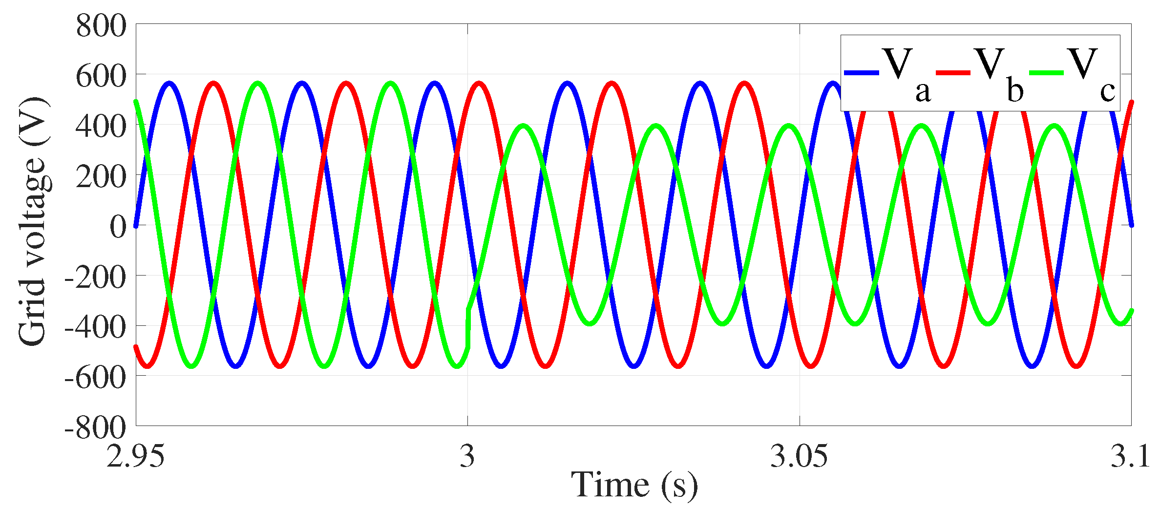
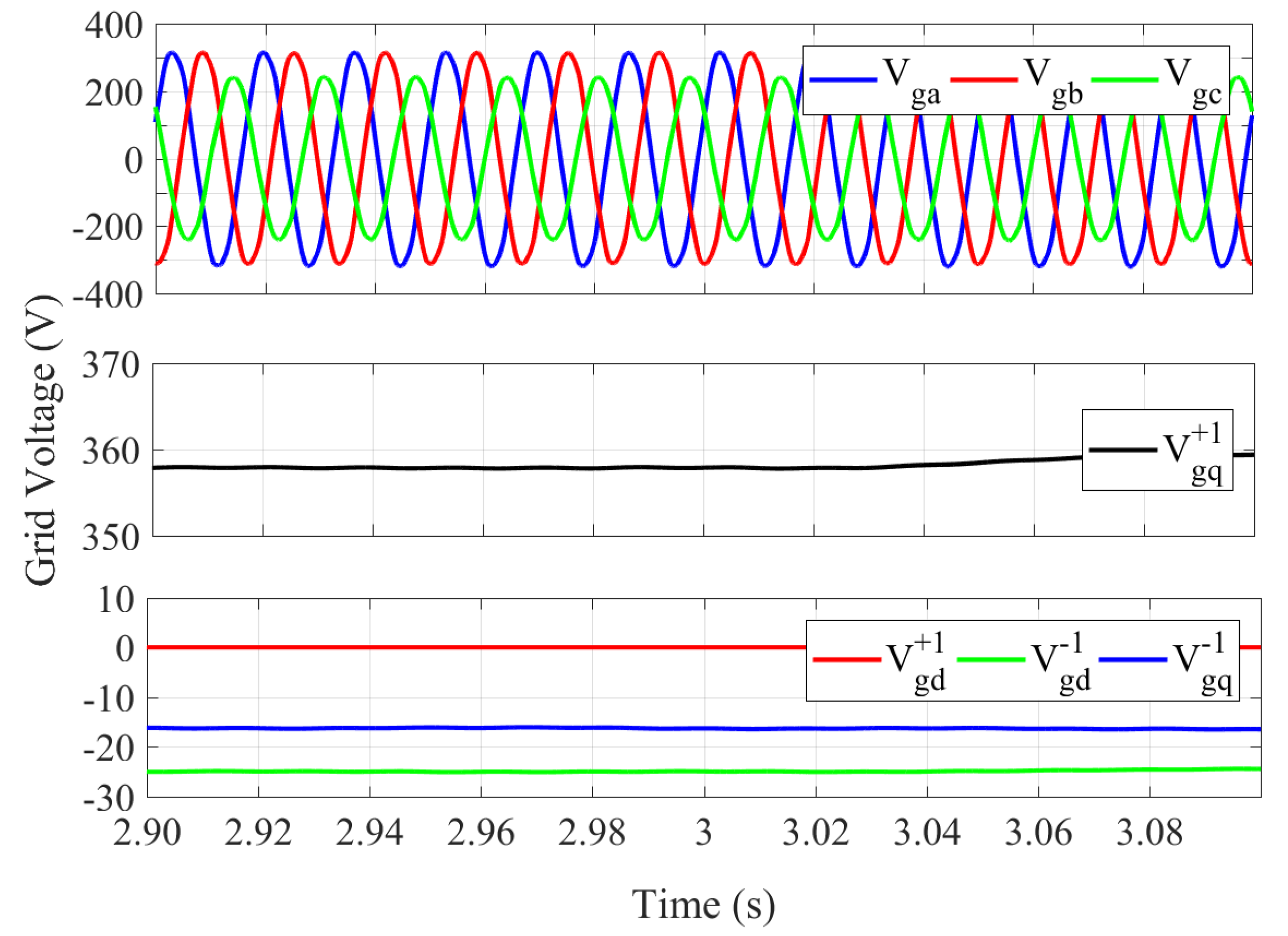
Figure 3 shows the unbalanced voltages caused by a single-phase sag on phase
c. The residual voltage during the sag equaled 70% of the original value.
Up to s, no power was injected through the stator; moreover, the slip considered, 0.3, was kept constant during all objectives.
At
s, power references were set, with
kW and
kvar. The reference rotor currents for each control objective were calculated according to
Table 1.
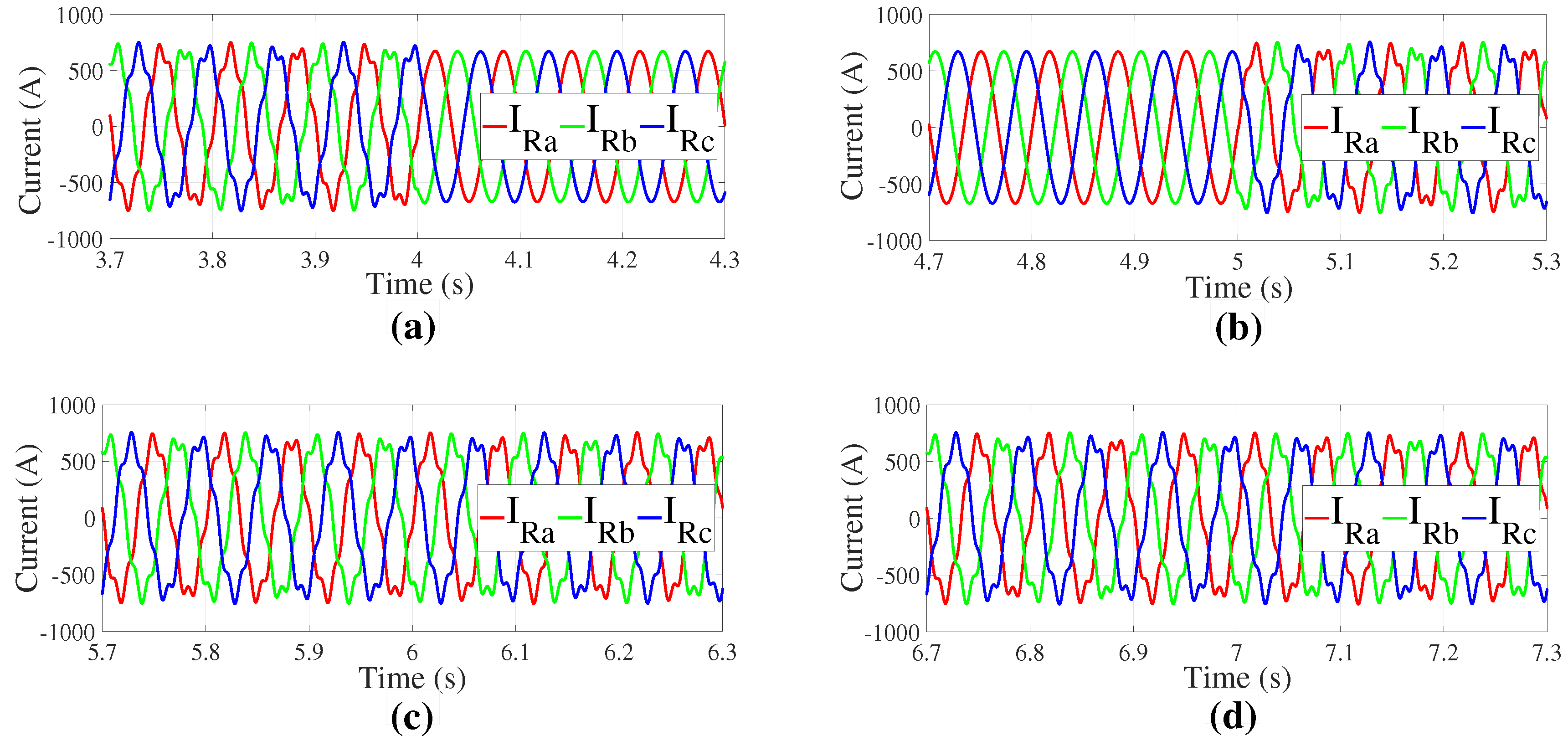
Figure 4a–d shows the behavior of the rotor current at the time of transition of Objectives I–IV, respectively. To verify the fulfillment of the first objective, the
Figure 4 shows the behavior change of the rotor current at the instant 4 s.
Figure 4 illustrates that the control strategy provided balance to the rotor currents when Objective I was employed. As mentioned previously, for practical purposes, this objective aims at the protection of the machine, if necessary. It does not contribute to the power quality improvement. The following objectives (II–IV) do not improve the rotor currents, being similar to what they were before Objective I.
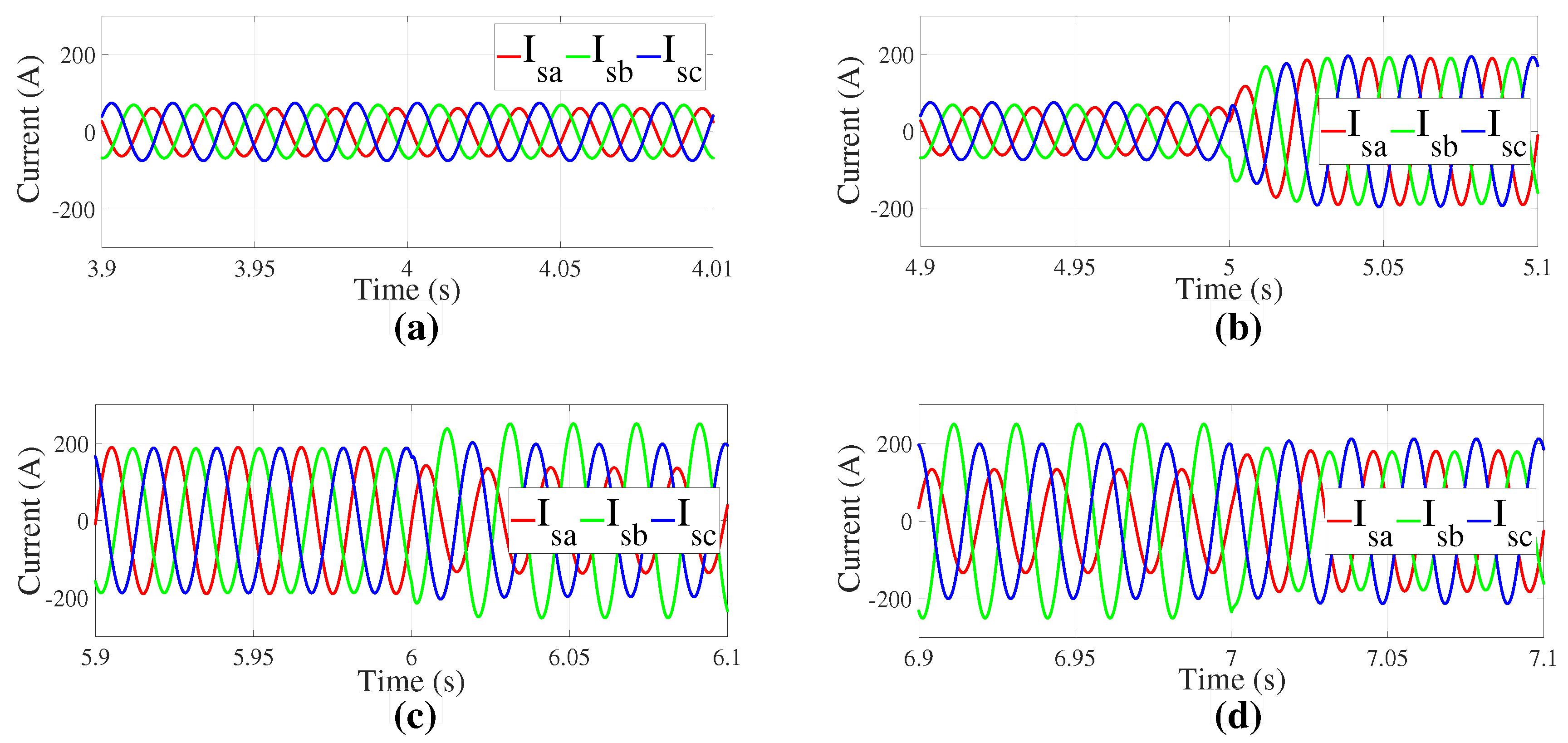
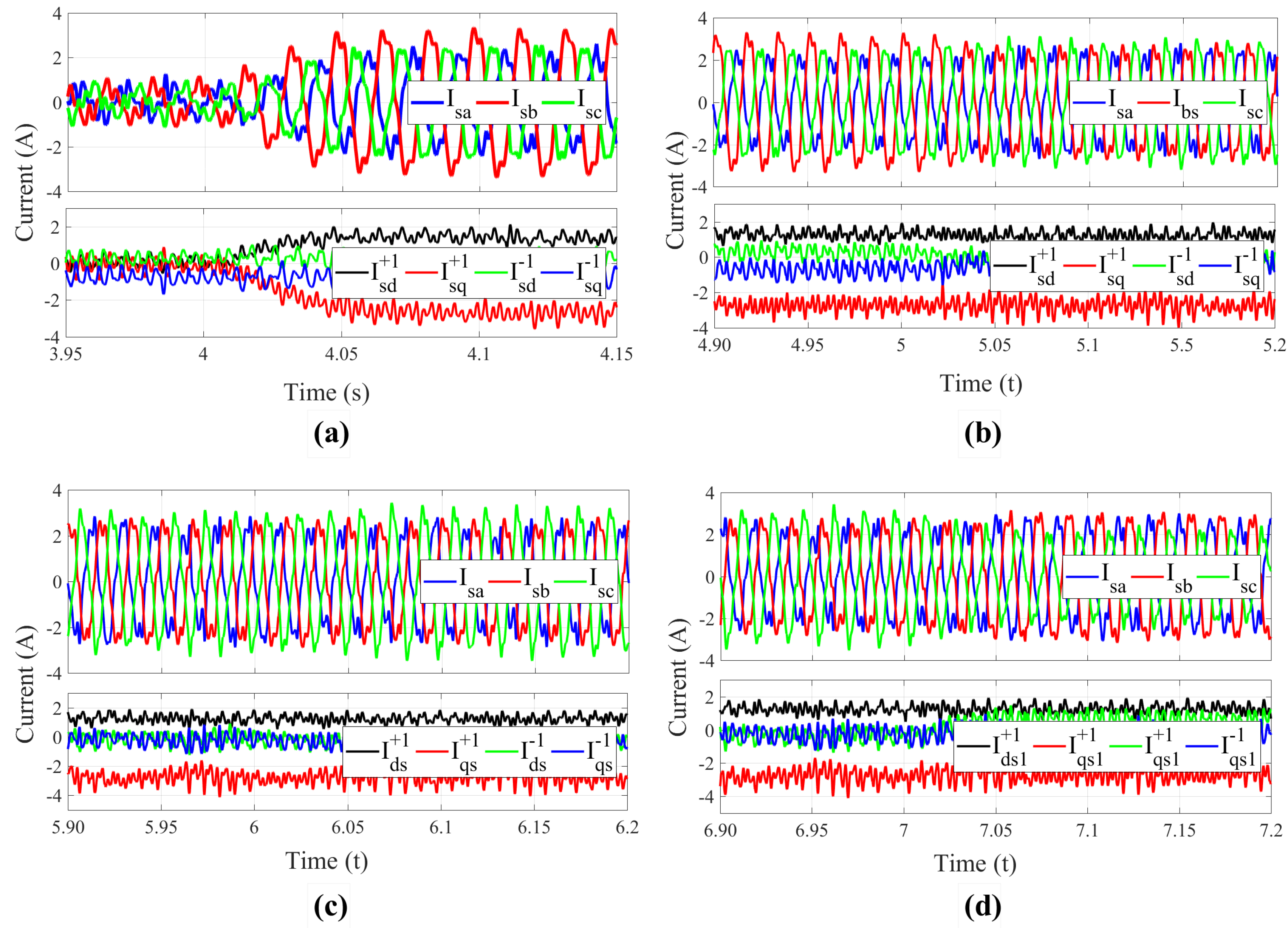
Figure 5a–d shows the behavior of the stator current in terms of the control Objectives I–IV, respectively.
Results in
Figure 5 confirm that Objective II was met (
Figure 5b) since the stator currents are balanced. The currents also experience an increase in magnitude. Objective I (
Figure 5a), however, did not lead to changes. Objectives III (
Figure 5c) and IV (
Figure 5d), at
and
s, respectively, kept the stator currents magnitude closer to the ones in Objective II; nevertheless, these objectives are not related to balancing the stator currents.
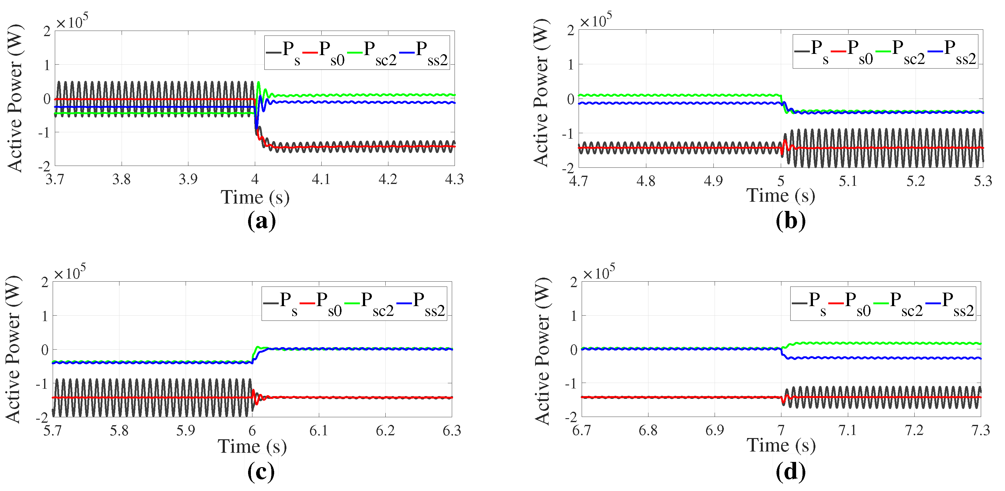
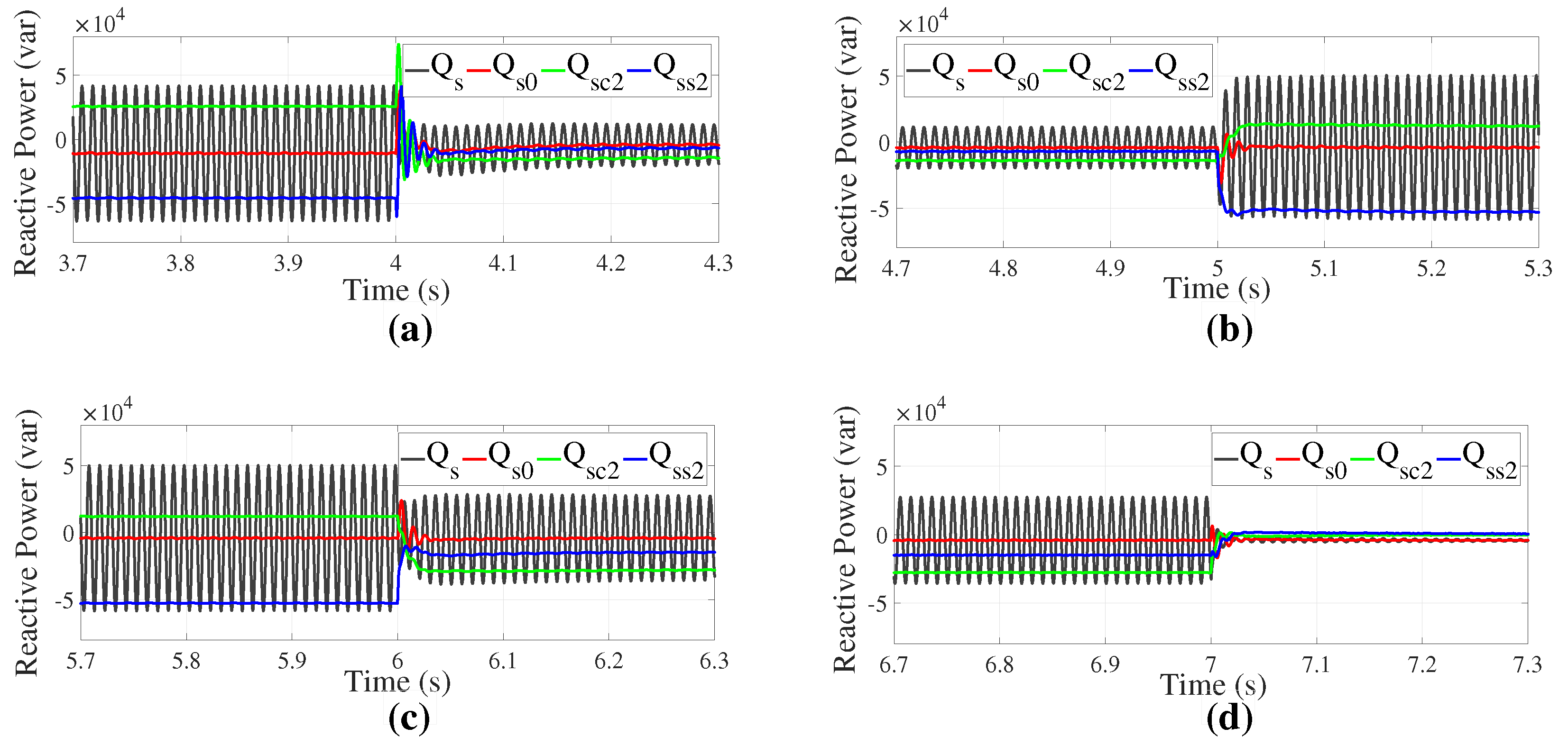
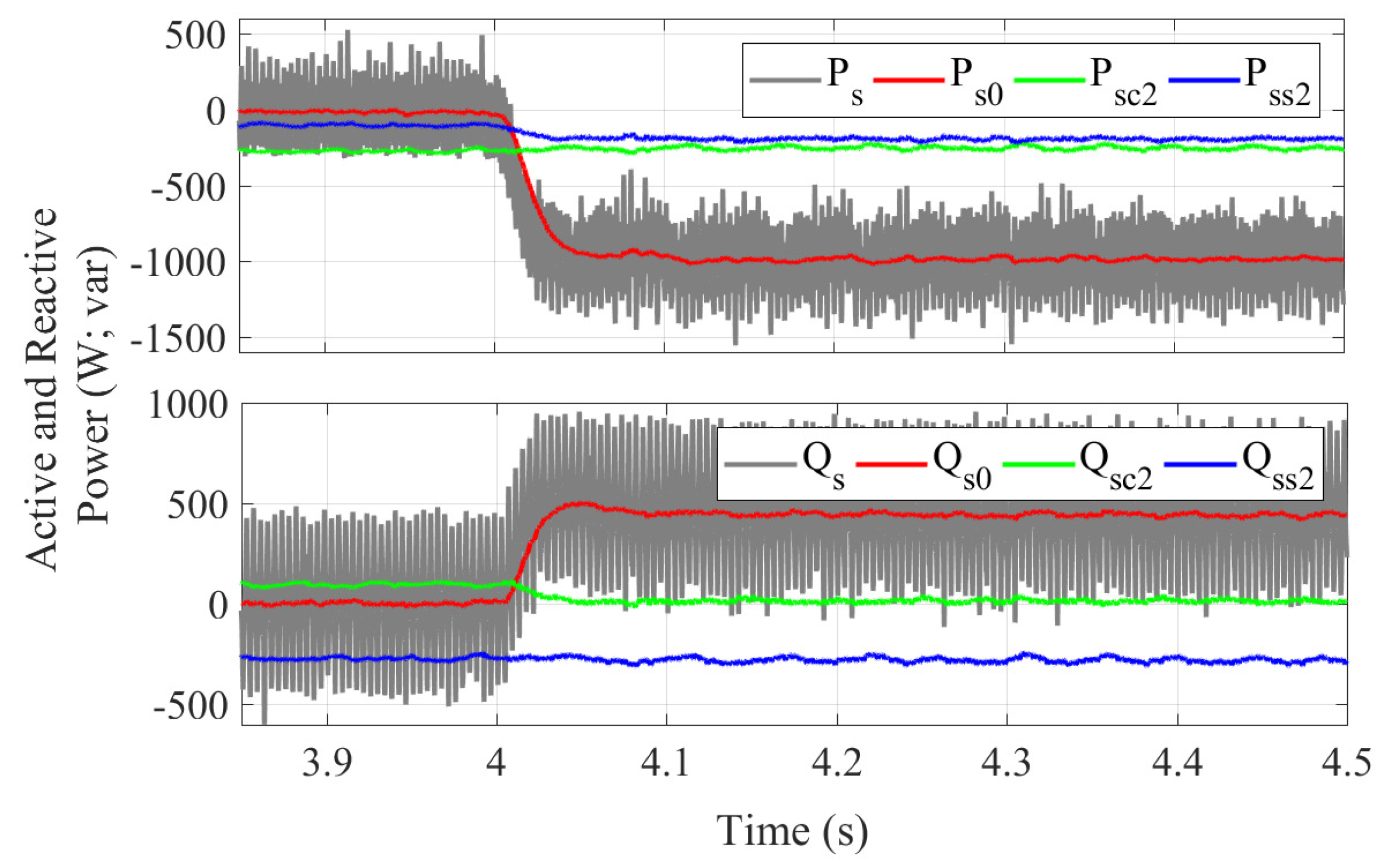
The system active and reactive power were also analyzed for each period of the simulation so that its behavior could be evaluated in more detail (see
Figure 6 and
Figure 7). These plots show the active and reactive power separated in their components
s,
,
and
. The plots also show the effects of changing from Objective I in (
Figure 6a and
Figure 7a) to Objective IV in (
Figure 6d and
Figure 7d).
When the Objective I (
Figure 6a and
Figure 7a) takes place, it is notable that the oscillating terms
and
are reduced.
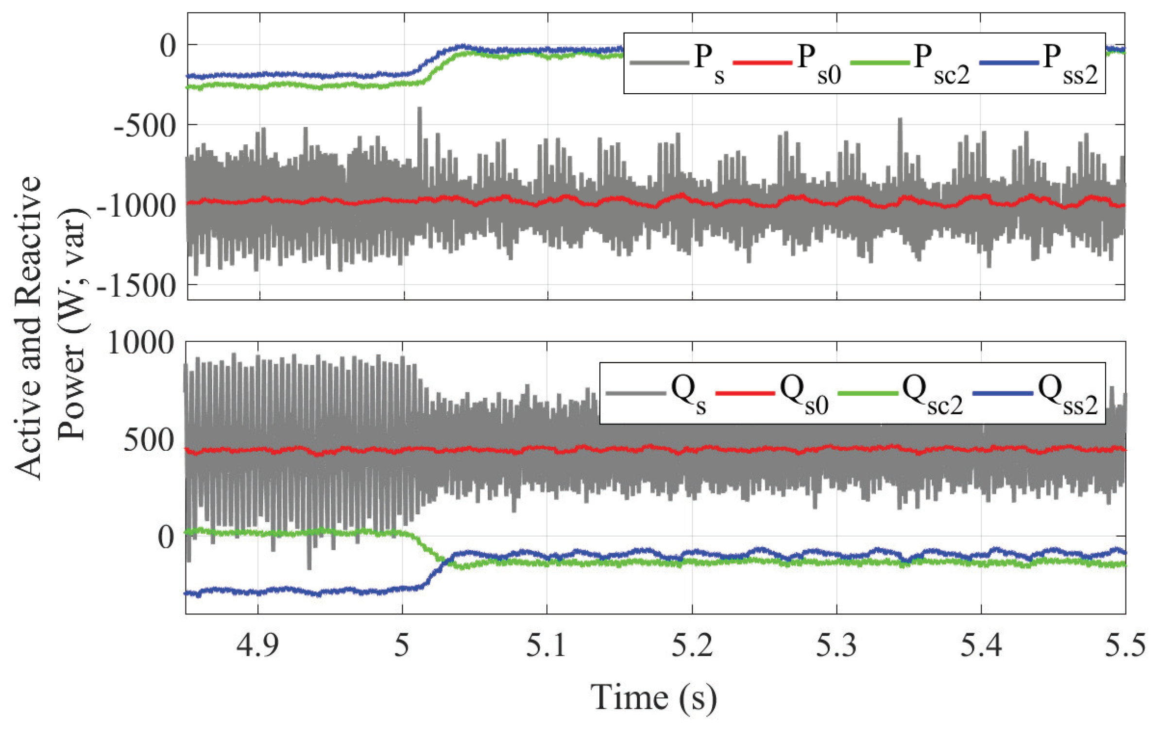
During the Objective II (
Figure 6b and
Figure 7b), the oscillating terms, especially
and
, increase the oscillation magnitude of
.
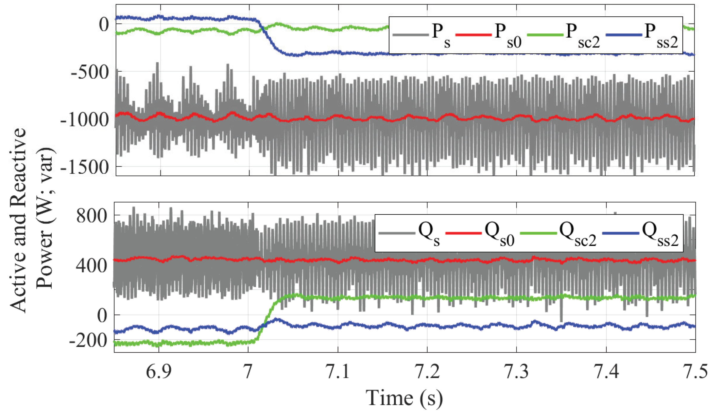
Finally, it is clearly seen in
Figure 6 and
Figure 7 that Objectives III (at
s) and IV (at
s) were met. Active power oscillations are reduced to nearly zero during Objective III, while the same happens with reactive power oscillations during Objective IV. It is important to highlight that all objectives are mutually exclusive, thus, with these control strategies, it is possible to provide either active or reactive power free of oscillations even during unbalanced scenarios.
The simulation results were consistent with what was presented earlier, validating it. Naturally, it is necessary to apply these same techniques beyond the scope of simulations, and to test them experimentally.
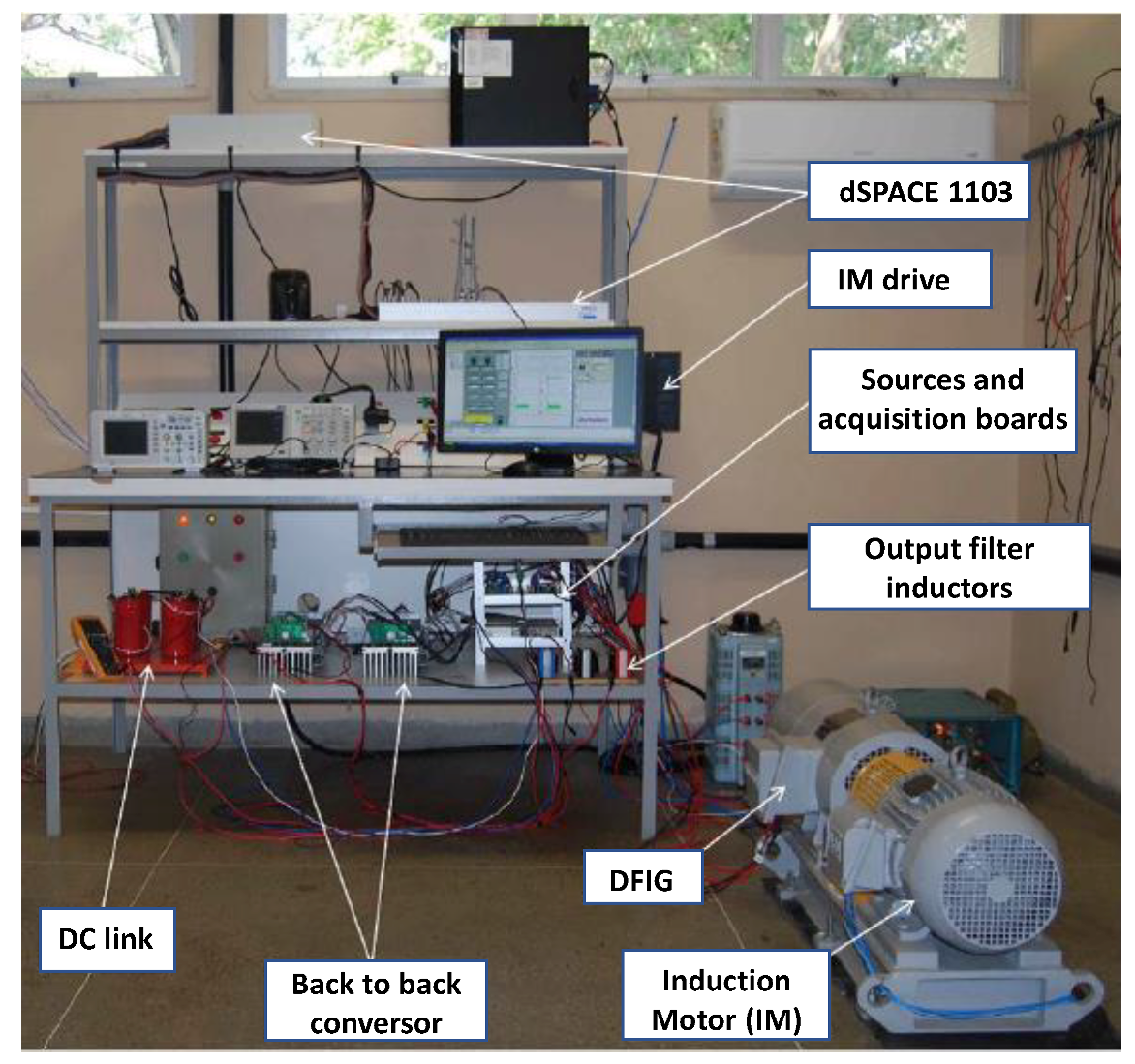
4.2. Experimental Results
Following the same sequence of simulation tests, the unbalanced grid voltage is shown in
Figure 8. The voltage sag considered was the same as in the simulation results, where the residual voltage on phase
c was 70% of the pre-fault condition.
Figure 8 specifically shows the voltage components in the positive and negative SRF.
The experimental tests focus on the analysis of the stator currents as well as the active and reactive power components, since these parameters have a greater importance to the power quality studies in the power grid. The analysis of the rotor current is only related as a strategy of protection of the machine. Their behavior predicted by the modeling was validated by the simulation results, therefore they were not presented. This study does not contribute directly to the focus of the article, which is found in the quality of energy, thus have not been detailed.
Figure 9 shows the behavior of the stator currents between beginning and the end of the proposed objectives in both the stationary axes
abc and sequence-separated
dq SRF.
The
Figure 9a–d clearly show a high harmonic distortion in the stator currents that remain in steady state throughout the experiment. It has been identified in previous tests that this occurrence is due to constructive problems of the machine itself, as the imbalance between the phases of the rotor circuit and has no relation with the experiment in question.
Confirming what was obtained in simulation results, the control strategy employed during the proposed objectives led to the increase of the stator currents amplitude. This is a side effect coming from the calculation of the reference rotor currents, shown in
Table 1. However, only during the Objective II (
Figure 9a), at
s, there is an apparent improvement of the grid currents with respect to their balance, thus ratifying what was obtained through simulations.
Analyzing the behavior of the power components,
Figure 10 shows the beginning of the active and reactive power injection through the stator, with
kW and
kvar.
and
are calculated by Equation (
26). The plots showing experimental results of the active and reactive powers, for each objective, were combined in a single figure to make it easier to visualize these variables during the different objective periods. The references for stator active and reactive power are kept constant throughout the whole experiment.
As shown in
Figure 11, the oscillating components of the active and reactive powers (
;
;
and
) are already reduced when Objective II takes place.
Figure 12 shows a reduction of the oscillating components below that expected for Objective III. The authors consider that this has happened because (
) was not taking into account when finding the equations shown in
Table 1.
At
s (
Figure 13), Objective IV takes place, which, similar to Objective III, reduces oscillations but does not completely eliminate them. A slight reduction in the amplitudes of the oscillating components of the reactive power is observed: Qsc2 goes from −230 var to 134 var and Qss2 changes from −117 var to −92 var.
4.3. Results Discussion
The main practical application for the strategy developed in this work is related to the power quality improvement. Power systems in general are susceptible to electrical disturbances, and the literature presents various equipment designed to mitigate damages caused by them. Synchronous compensators have a power storage system with flywheel and have a long life expectancy with a high number of loading and unloading cycles, which make them an excellent device for integration into power systems when compared to other power storage technologies. In addition, they have the advantage of being able to offer compensation in oscillations of the active and reactive power or even in the current of the system, when necessary. In this context, the control strategy developed in this work can be applied to the current synchronous compensators, making its application more versatile with the four control strategies presented.
The main practical advantages for the proposal presented in this work can be summarized as follows:
The use of a machine with more degrees of freedom than the machine used in the conventional solution, because it is fed in both stator and rotor circuits. This gives the compensation system more flexibility to quickly adapt to new situations.
The possibility of compensating by the rotor side converter and the grid side converter too. This enables more power quality for the system to be compensated.
Presentation of four control strategies, each one able to compensate for oscillations in different electrical quantities, namely: active power, reactive power, rotor currents and stator currents. The reactive power compensation is contemplated by all strategies presented.
In this subsection, a comparison is made between the control strategy used in this work and other recent methods found in the literature that have similar objectives. When possible, some comparisons between results are also made to highlight the advantages and limitations of this control with the most current.
The penetration level of Wind Energy Conversion Systems (WECS) is constantly increasing. As a result, many works with this topic seek solutions involving stability, controllability and power quality of electric machines, such as the DFIG. The work presented in [
19], for instance, controls the DFIG connected to the network with a Series Dynamic Voltage Restorer (SDVR) under voltage sag scenarios. The authors show that this strategy not only is efficient and simple, but also has fast response and uses low cost devices to mitigate the effects of a three-phase fault. However, the control strategy of this work does not provide solutions for the presence of negative sequence in the system.
The authors in [
20] presented a configuration that combines a wind turbine based on a DFIG and the operation of a Solid State Transformer (SST), aiming at improving power quality by compensating reactive power, reducing harmonics and consequently improving the power factor. This is an interesting work because it uses a hysteresis current control without using PLL, also eliminating the need for a STACOM in (WECS) to meet grid codes. Although it shows excellent reactive power compensation in the results, this proposal does not offer any strategy to provide active power as it functions similarly to a STATCOM.
In Ref. [
21], a control strategy for impedance remodeling based on Variable Frequency Resistance (VFR) and Chebyshev filter is proposed. The High Frequency Resonance (HFR) damping control and harmonic current suppression are performed simultaneously providing a power quality improvement for the DFIG connected to the grid. The authors presented excellent results for harmonics reduction. These results are superior to the ones obtained in Objectives I and II of this work (simulation and experimental). However, Nian and Pang [
21] did not offer any other solutions beyond this one to improve power quality, such as active and reactive power compensation, which are presented in this article.
Focusing more on the protection of the electric machine in scenarios where high currents are flowing in the DFIG rotor circuit, such as voltage sag scenarios, Chowdhury and Chowdhury [
22] introduced a method for compensation used to sink 50% of the voltage and voltage interruption, which prevents the isolation of the DFIG from the grid and guarantees the protection of the machine. The method uses a three-phase inverter that converts the DC voltage of a battery energy storage system. This work presents excellent results for the reduction of high currents in the rotor and stator even for the critical case of total voltage interruption. Although the proposed control proves to be very interesting for the protection of the machine, the work does not present scenarios with asymmetrical voltage sags; moreover, the addition of a new device in the system can be costly.
In a context that goes beyond the application in wind turbines, ref. [
23] used a flywheel synchronous compensator with a permanent magnet synchronous machine. The work proposes to improve power quality and the stability of the local system by compensating voltage sags. The results show only the compensation for three-phase voltage sags. The main limitation of the developed strategy is that it compensates only the voltage processing reactive power. It does not present other solutions for the power quality improvement, such as eliminate the oscillating component of the active power, for example. This inability control makes this solution more limited, when compared to the strategy proposed in this work.
The comparison between methods and results with recent closely related works points towards the fact that the proposed control is a feasible solution for the improvement of power quality.
5. Conclusions
This study allowed a thorough analysis of how the proposed strategy can adapt the operation of the DFIG to work as a synchronous compensator. The main idea is that it is possible to adapt control techniques that are normally employed on the DFIG operating as a generator and provide alternatives for supplying oscillation-free active and reactive power as well as balanced currents to the power grid, specifically in scenarios where the grid voltage is unbalanced.
Simulation results verified that the technique studied met the objectives proposed for the considered scenarios. With respect to the rotor and stator currents, there was a considerable reduction of the imbalance and distortions, which can be verified in Objectives I and II, respectively. In the case of the active and reactive powers, Objectives III and IV drastically reduced the oscillating components and .
Overall, the experimental results confirmed the tendency shown in the simulation results, that is, promoted the convergence to zero of the negative stator current components in the axes (Objective II) and reduced oscillating components in the active power (Objective III) and reactive power (Objective IV). The reduction of oscillating components in the active and reactive power was lower than expected; the authors believe this happened because was not taken into account when modeling the electrical machine.
The experimental results were limited by the rating power of the electrical machine used in the laboratory (as well as the converters), which increased the influence of the resistance of the stator windings in the experimental results. It was also verified, in previous tests, that the generator has constructive problems, probably related to the stator windings. These two limitations caused, respectively, undesirable oscillations in the stator current and the active/reactive power.
Nevertheless, it is intended in the next experiments to validate the simulations with a machine with greater power. It is also possible to extend future tests to more critical cases, such as voltage interruptions, to verify the scope of performance of the proposed model. Future work is also desirable to identify the experimental plant. This would allow greater accuracy in the calculation of the controller parameters, increasing the reliability and performance of the system.

 ,
, 


