1. Introduction
At present, permanent magnet (PM) machines, due to their high torque density and efficiency, are widely used in vehicle drives applications. However, it is known that the constant PM excitation causes difficulties in air-gap flux controlling. Therefore, classical machines with PMs suffer from limited flux control capability, especially in a constant power operating region. Consequently, machines with hybrid excitation (controllable flux) are explored and designed in order to obtain drives with high efficiency and a wide speed range.
The aim of the paper is to analyze new rotor structures of an electric controlled permanent magnet synchronous (ECPMS) machine with axial flux bridges. Previous versions of this machine have been developed, optimized, and widely tested in [
1,
2,
3], and similar solutions are discussed in [
4,
5,
6,
7,
8,
9]. The goal of this research was to present another rotor design of an ECPMS machine and discuss its suitability for vehicle traction applications where the energy management problem is of highest importance. Therefore, in order to increase vehicle range, each component of the electric drive should be developed and optimized to improve its efficiency.
2. An ECPMS Machine with Axial Flux Bridges
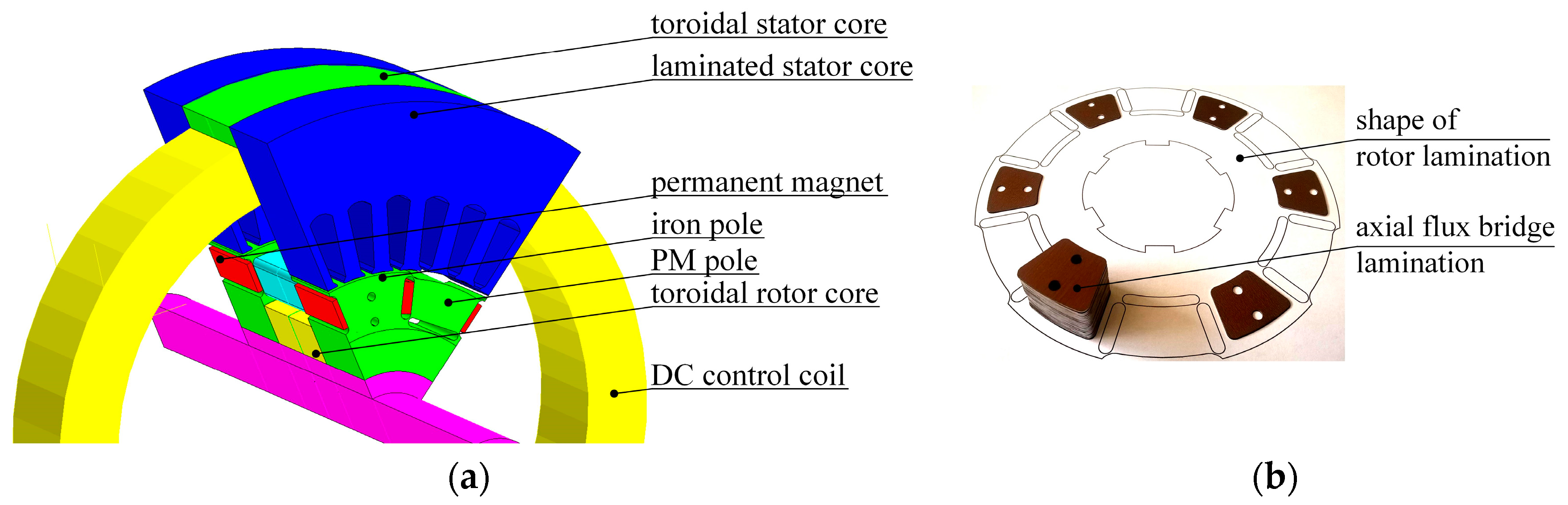
Field controlling (strengthening and weakening) in the ECPMS machine (
Figure 1a) is performed using additional field generating winding (DC coils). Suitable adjustment of DC coil current
IDC allows for the control of the stator flux linkage Ψ
s in the required range. To increase the performance and a control-field efficiency of the machine, axial flux bridges located between iron poles (IPs) of the machine have been proposed.
Figure 1a shows 12 poles of the ECPMS machine with a novel concept of rotor structure formed by IP and PM poles with U-shape flux barriers. An axial flux bridge lamination and its location on a rotor lamination are shown in
Figure 1b in detail. The main objective of the bridges is to change the direction of the flux distribution in the middle part of the rotor and to reduce the mass of magnetic active parts of the rotor.
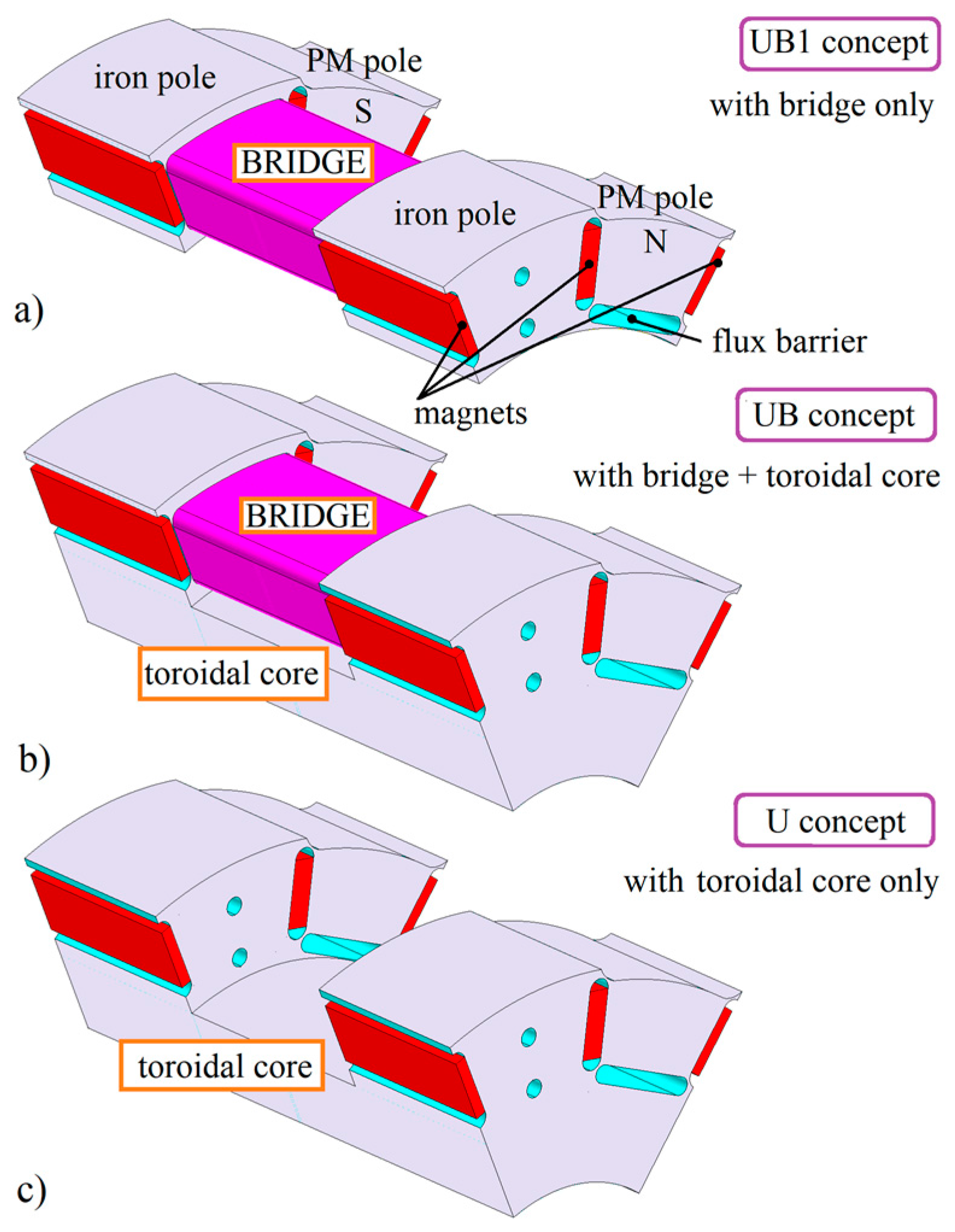
Figure 2 shows three rotor concepts of the ECPMS machine that have been developed to evaluate its field-weakening features and rotor iron losses using 3-Dimensional Finite Element Analysis (3D-FEA):
1. The U-shape with Bridges 1 (UB1) concept (
Figure 2a) with six axial flux bridges without a toroidal rotor core;
2. The U-shape with Bridges (UB) concept (
Figure 2b) with six axial flux bridges including the toroidal rotor core, as shown in
Figure 1a;
3. The U-shape (U) concept (
Figure 2c) with a toroidal rotor core only, fixed in the middle of the active parts. It should be noted that in this study the concept U is the fundamental concept that has already been partially investigated in [
10,
11].
3. 3D-FEA Predictions of the ECPMS Machine
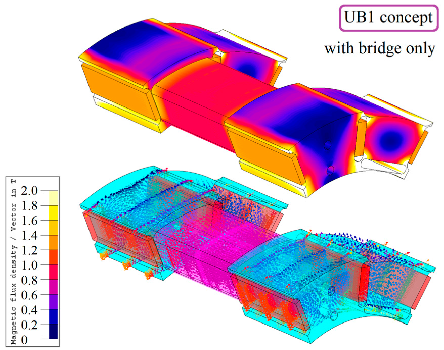
As mentioned above, the target of the study was to demonstrate the influence of axial magnetic bridges in magnetic circuit of the hybrid excited machine on field-weakening and -strengthening features and iron loss distribution. For this, the 3D-FEA was used. Due to the rotational symmetry of magnetic flux distribution in the considered machine and in order to reduce the calculation cost, a FEA model of the machine was limited to one-sixth of the machine structure.
Figure 3 shows the magnetic flux distribution in the UB1 rotor concept of the ECPMS machine performed by using the Flux3D software package (Version 10.4) developed by Cedrat, Ltd. (Meylan, France).
It should be noted that the 3D-FEA model of the ECPMS machine takes into account the armature winding and the DC coil giving accurate predictions with regard to the loss calculation.
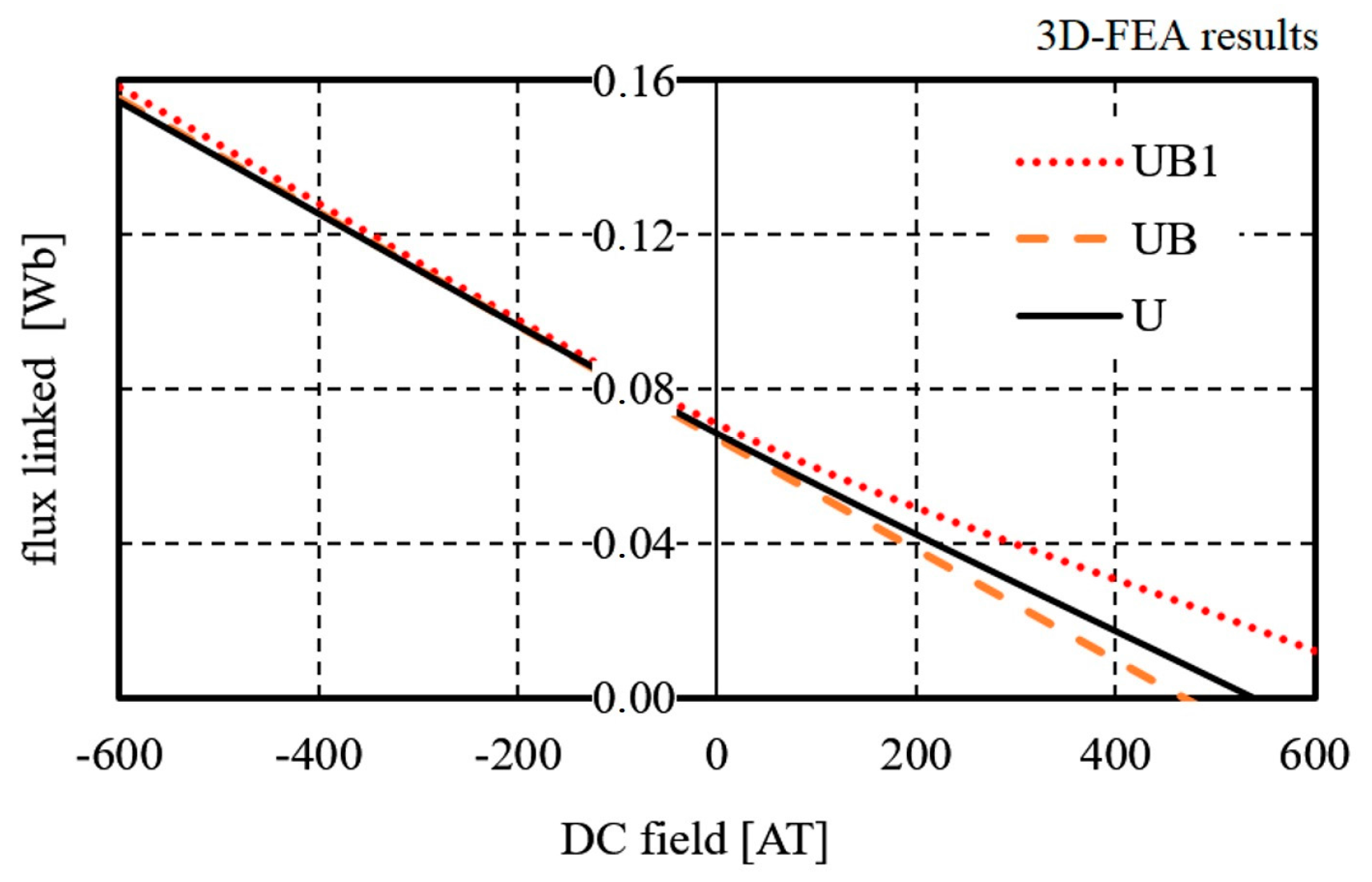
Figure 4 presents characteristics of magnetic flux linkage Ψ
s versus DC field excitation for the three rotor concepts. The excitation coil has 300 turns. For comparative purposes, 3D-FE analysis were carried out at no-load armature current conditions and at three different DC coil ampere-turns (ATs):
flux-weakening (AT = −600),
flux-strengthening (AT = 600),
no-load (AT = 0).
Table 1 shows 3D-FEA results at no-load phase magnetic flux linkage Ψ
s for the UB1, UB, and U concepts. Moreover, the presented results demonstrate a range of field weakening of the machine as ratio Ψ
s_0/Ψ
s_2A and a full field control range as ratio Ψ
s_−2A/Ψ
s_2A.
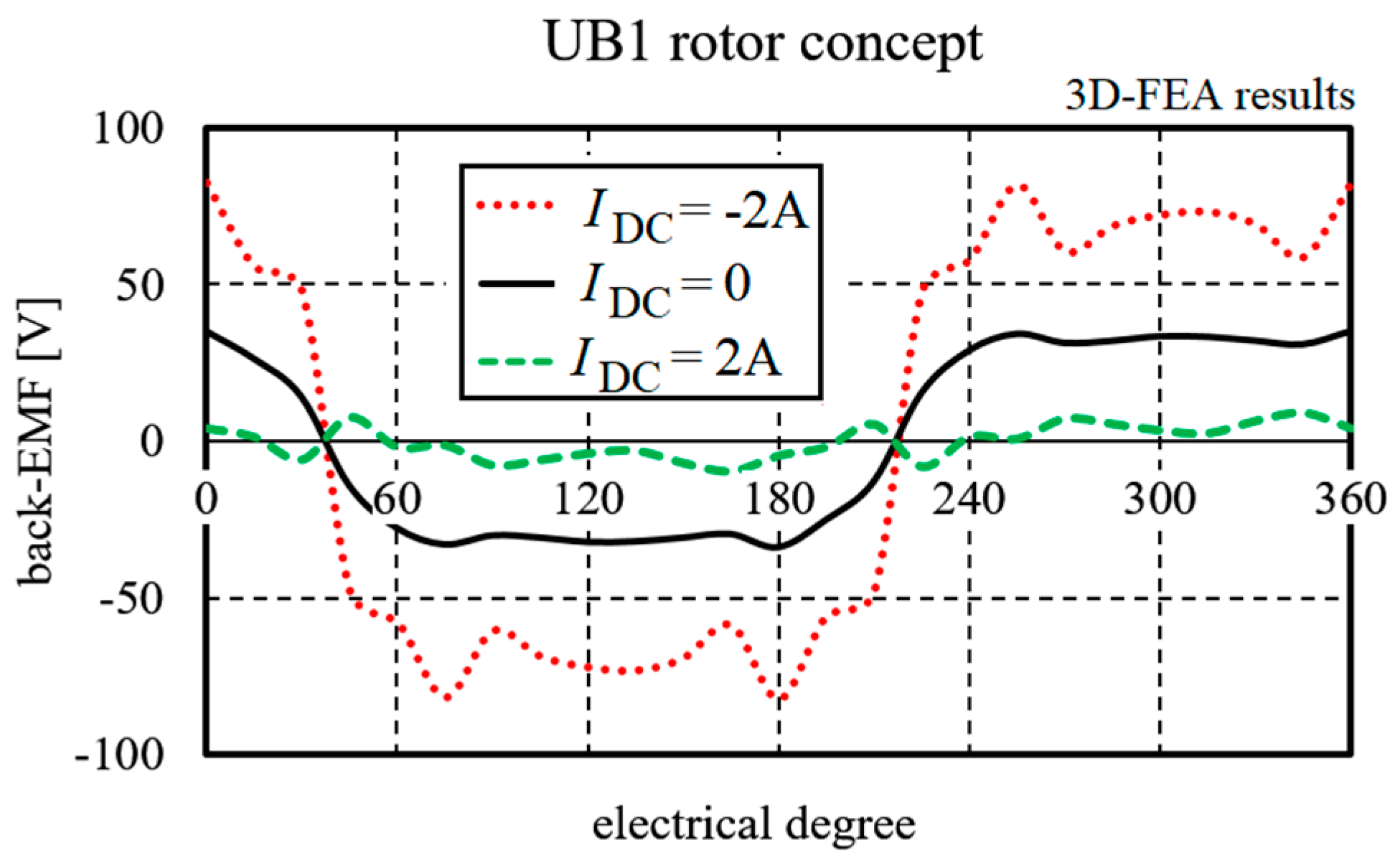
According to these results, by using the rotor structure based on the U idea, the ECPMS machine with perfect field-weakening capability can be build. The results proved that the stator flux linkage can be decreased by at least five times. The effect was clearly observed in all presented concepts. As a consequence, the back electromotive force (back-EMF) waveforms can be adjusted successfully using DC field excitation, even in the machine with a UB1 rotor concept, as shown in
Figure 5.
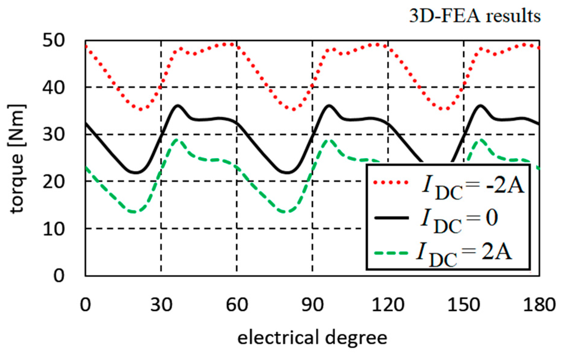
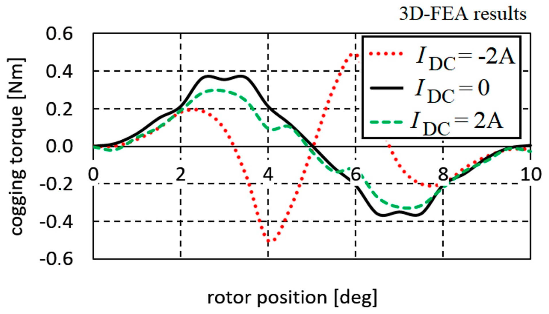
Additionally, FE analysis of the electromagnetic torque ripple (
Figure 6) and cogging torque (
Figure 7) at different DC field excitations has been carried out.
4. Rotor Iron Losses Calculation
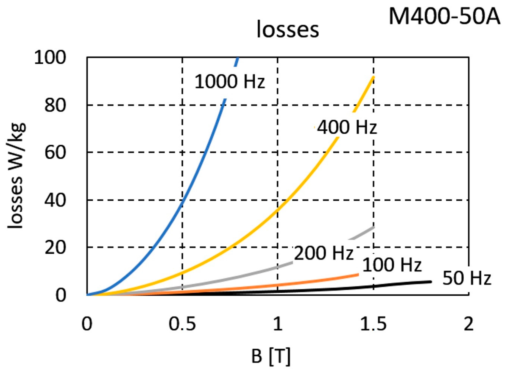
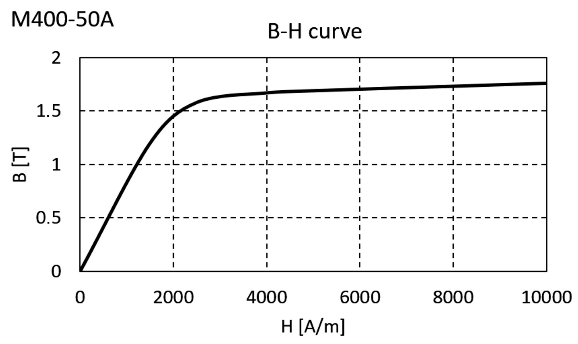
In the proposed structures of the machine, a rotor core and a stator core with the axial bridges were made of laminated iron (sheet type M400-50A with a thickness of 0.5 mm) with losses and a
B–H curve presented in
Figure 8 and
Figure 9. The shaft is made of a solid nonmagnetic material. Moreover, the PMs type N38SH (ENES Magnesy LP, Warsaw, Poland) used in this study have a remnant flux density of 1.23 T and a coercive force of 907 kA/m.
In order to compare iron losses generated in ferromagnetic materials used in the rotor structure, where the passing magnetic flux through the rotor is performed in different ways, losses were computed with Flux3D Transient Magnetic applications with the Bertotti method [
12,
13]. According to this method, the iron losses have been defined as
According to this method, iron losses can be divided into three different parts: hysteresis losses, eddy current losses, and excess losses, where
kh is the coefficient of hysteresis losses,
ke is the coefficient of losses in excess,
σ is the conductivity of the material (coefficient of conventional eddy currents losses),
d is the thickness of the lamination,
kf is the coefficient of filling (the stacking factor) that considers the electrical insulation of the laminations of the magnetic core,
f is the frequency, and
Bm is the peak value of the magnetic flux density. In this case, coefficients
ke and
kh were determined using a formula on two points (first:
P = 1.27 W for
B = 0.5 T; second:
P = 4.15 W for
B = 1.0 T) corresponding to the curve at
f = 100 Hz (
Figure 8), in order to have a set of two equations for two unknowns. The results of the estimation have been shown in
Table 2. Furthermore, in computational algorithm, a nonlinear
B–
H curve of M400-50A lamination (
Figure 9) was used.
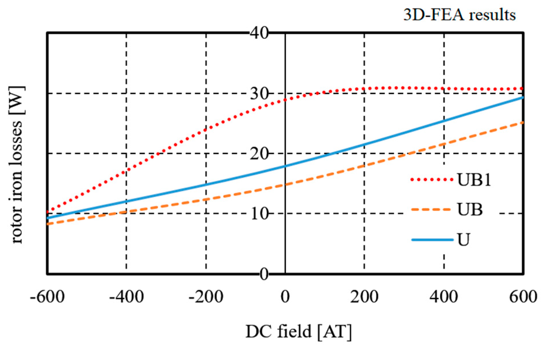
Finally, some essential results of the predicted performance of the ECPMS machine for the analyzed rotor structures obtained from the 3D field analysis are presented in
Table 3. Moreover,
Figure 10 shows rotor iron losses at different DC field excitations for all rotor concepts.
It should be stressed that in this paper only losses in the rotor core have been analyzed. In other papers, analyses regarding losses in the stator core can be found, e.g., [
14].
5. Conclusions
As mentioned above, the aim of this paper was to develop magnetic rotor structures for the modified ECPMS machine with high field-weakening and strengthening capabilities. The presented results show that, by using the rotor structure based on the U idea with PMs and a flux barrier U-shape arrangement, it is possible to construct an ECPMS machine with high field-weakening capabilities. Based on the 3D-FEA predictions it can be concluded that, in all presented rotor designs, the stator flux linkage of the machine can be decreased by at least five times. Due to the conceptual character of the work and the huge computational costs related to 3D field calculations, the full mechanical characteristics and efficiency maps of the machine will be performed in further investigations.
The presented results indicate clearly that axial magnetic bridges in the UB1 concept, replacing the toroidal rotor core of the ECPMS machine with U-based concept, can reduce the mass of the rotor by 40% without significantly reducing the field-weakening capability and machine efficiency. Moreover, the axial bridges with additional DC coils winding around the bridges can become a new kind of ECPMS machine excitation. Described concepts indicate new directions in the search of design solutions for the ECPMS machine with excellent field-control capabilities and good efficiency. Obtained simulation results show that the field-control ratio equal to 10:1 can be effectively obtained in the machine, showing its good application potential in the development of adjustable speed drive applications.
The paper presents the concept and preliminary results of simulation tests, which were conducted to propose a new field distribution within the ECPMSM machine. At this stage of the research, there are no experimental results using the U-based rotor concept. The previous experimental results of the ECPMSM with different rotor structures show large convergence with the simulation results. It can be assumed that these results are reliable, so they confirm the theoretical considerations presented in this paper.
Acknowledgments
This work has been supported with a grant of the National Science Centre, Poland (2015/17/B/ST8/03251).
Author Contributions
All authors worked on this manuscript together. Marcin Wardach and Piotr Paplicki performed the finite element model, executed simulations, and analyzed the obtained data. Ryszard Palka defined the methodology, analysis, and conclusions of the paper. All authors revised and approved the final version of the paper.
Conflicts of Interest
The authors declare no conflict of interest.
References
- Di Barba, P.; Mognaschi, M.E.; Bonislawski, M.; Palka, R.; Paplicki, P.; Piotuch, R.; Wardach, M. Hybrid excited synchronous machine with flux control possibility. Int. J. Appl. Electromagn. Mech. 2016, 52, 1615–1622. [Google Scholar] [CrossRef]
- Paplicki, P.; Wardach, M.; Bonisławski, M.; Pałka, R. Simulation and experimental results of hybrid electric machine with a novel flux control strategy. Arch. Electr. Eng. 2015, 64, 37–51. [Google Scholar] [CrossRef]
- Putek, P.; Paplicki, P.; Pulch, R.; ter Maten, E.J.W.; Günther, M.; Palka, R. Multi-objective topology optimization of a permanent magnet machine to reduce electromagnetic losses and cogging torque. Int. J. Appl. Electromagn. Mech. 2017, 53, S103–S212. [Google Scholar] [CrossRef]
- Wardach, M.; Paplicki, P.; Palka, R. U-shape flux barriers and axial flux magnetic bridges in rotor of hybrid excited machine. In Proceedings of the 2017 18th International Symposium on Electromagnetic Fields in Mechatronics, Electrical and Electronic Engineering (ISEF) Book of Abstracts, Lodz, Poland, 14–16 September 2017. [Google Scholar] [CrossRef]
- Tapia, J.A.; Leonardi, F.; Lipo, T.A. Consequent-Pole Permanent-Magnet Machine with Extended Field-Weakening Capability. IEEE Trans. Ind. Appl. 2003, 39, 1704–1709. [Google Scholar] [CrossRef]
- Meidensha, K.K. Hybrid Excitation Type Permanent Magnet Synchronous Motor. U.S. Patent US5,682,073, 28 October 1997. [Google Scholar]
- Amara, Y.; Vido, L.; Gabsi, M.; Hoang, E.; Ben Ahmed, A.H.; Lecrivain, M. Hybrid Excitation Synchronous Machines: Energy-Efficient Solution for Vehicles Propulsion. IEEE Trans. Veh. Technol. 2009, 58, 2137–2149. [Google Scholar] [CrossRef]
- Mbayed, R.; Salloum, G.; Vido, L.; Monmasson, E.; Gabsi, M. Hybrid excitation synchronous motor control in electric vehicle with copper and iron losses minimization. In Proceedings of the IECON 2012—38th Annual Conference on IEEE Industrial Electronics Society, Montreal, QC, Canada, 25–28 October 2012; pp. 4886–4891. [Google Scholar]
- Kong, L.; Wen, X.; Fan, T. A new method to plan the optimal field excitation current trajectory in a hybrid excitation machine. In Proceedings of the 2011 International Conference on Electrical Machines and Systems, Beijing, China, 20–23 August 2011; pp. 20–23. [Google Scholar]
- Paplicki, P. A novel rotor design for a hybrid excited synchronous machine. Arch. Electr. Eng. 2017, 66, 29–40. [Google Scholar] [CrossRef]
- Paplicki, P. Influence of Magnet and Flux-Barrier Arrangement on Flux Control Characteristics of Hybrid Excited ECPMS-machine. Elektron. Elektrotech. 2017, 23, 15–20. [Google Scholar] [CrossRef]
- Bertotti, G. General properties of power losses in soft ferromagnetic materials. IEEE Trans. Magn. 1988, 24, 621–630. [Google Scholar] [CrossRef]
- Młot, A.; Korkosz, M.; Łukaniszyn, M. Iron loss and eddy-current loss analysis in a low-power BLDC motor with magnet segmentation. Arch. Electr. Eng. 2012, 61, 33–46. [Google Scholar] [CrossRef]
- Feng, Y.; Zhang, C. Core Loss Analysis of Interior Permanent Magnet Synchronous Machines under SVPWM Excitation with Considering Saturation. Energies 2017, 10, 1716. [Google Scholar] [CrossRef]
© 2018 by the authors. Licensee MDPI, Basel, Switzerland. This article is an open access article distributed under the terms and conditions of the Creative Commons Attribution (CC BY) license (http://creativecommons.org/licenses/by/4.0/).


