Conceptual Synthesis of Speed Increasers for Wind Turbine Conversion Systems


Abstract
:1. Introduction
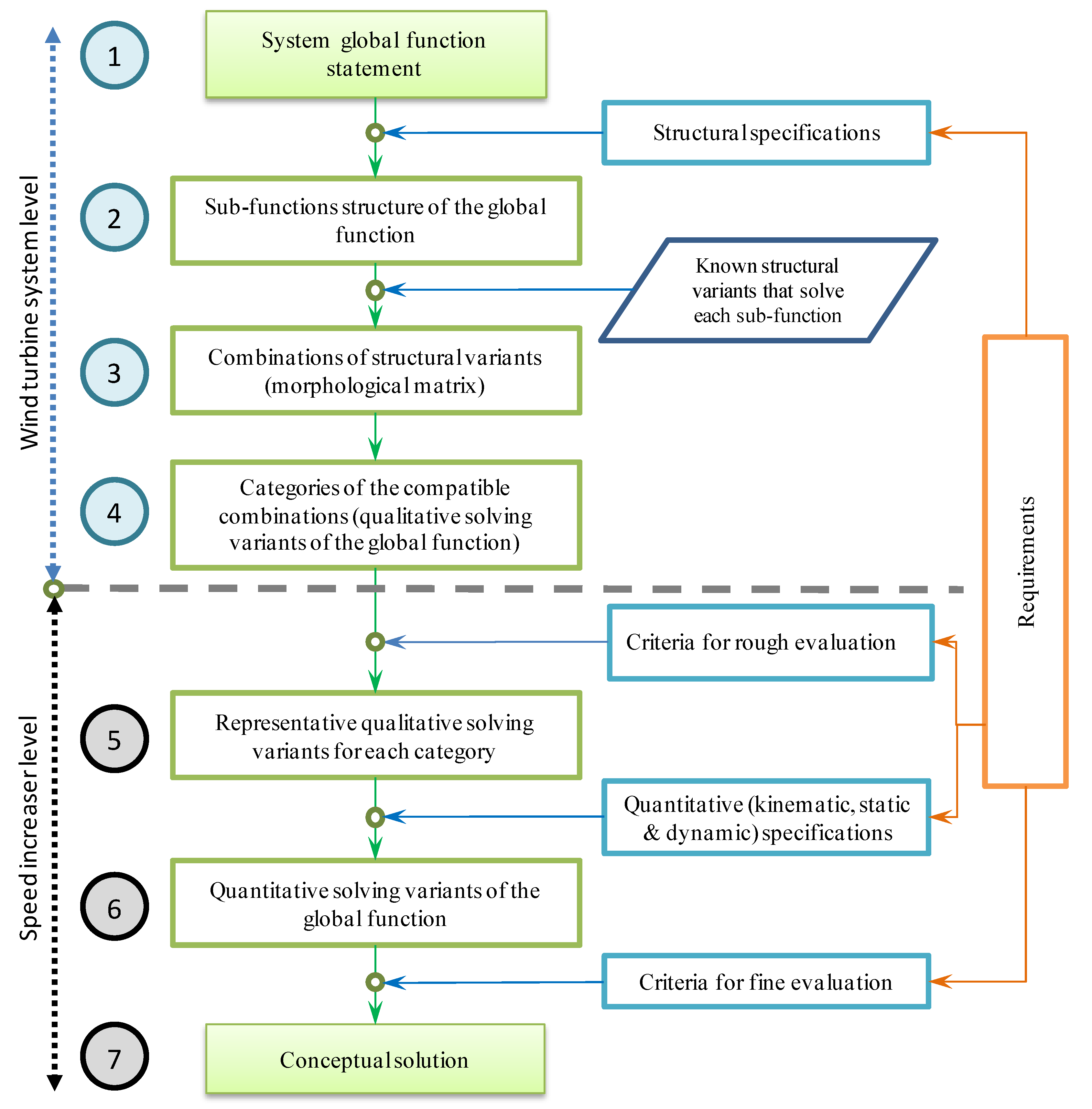
2. Proposed Algorithm for Conceptual Synthesis of Wind Turbine Systems
- Statement of the system global function according to the requirements, by defining the correlations between its input and output entities of material, energy and information types. Only the simplified case in which the WT global function is reduced to the energy flow (the main flow) is considered in this paper; the other two secondary flows (of material and information type) are ignored as they have insignificant relevance for the paper subject. The requirements list is defined by a specialized team according to the customer needs and represents the input in the conceptual design process. The requirements are stated in terms of qualitative and quantitative specifications (of structural, geometric, kinematic, static, dynamic and other types), as well as a set of technical and economic criteria used to evaluate the resulting variants.
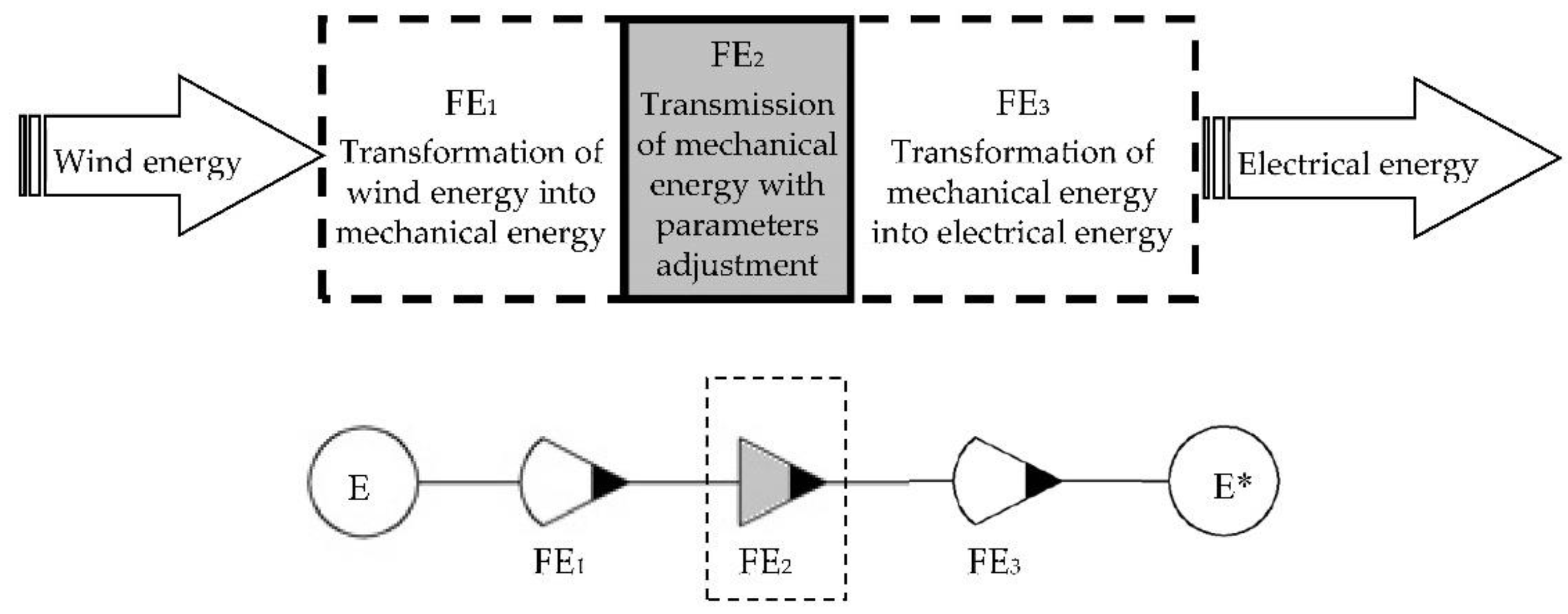
- Description of the sub-functions structure of the global function based on the structural specifications in the requirements list, i.e., defining the component sub-functions (either elementary or composite) and the relationships established between them. In the structure of WT global function, three main sub-functions are considered relevant in this study: the conversion of wind energy into mechanical energy, followed by the change of the mechanical energy state parameters (speed and torque) and, finally, the conversion of mechanical energy into electricity.
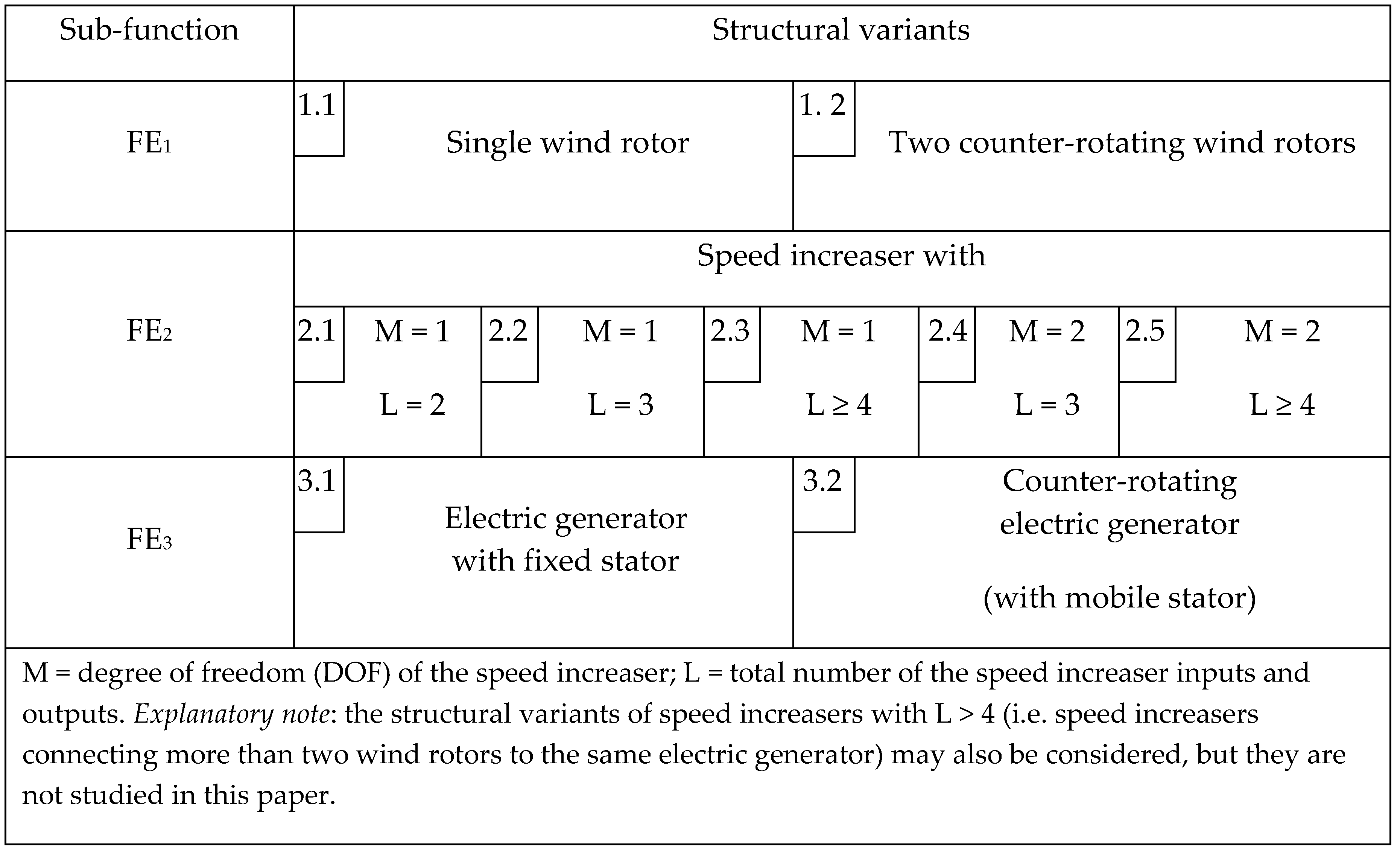
- Identification of known structural variants that solve each sub-function and generation of qualitative solving variants of the global function as compatible combinations of the structural variants for all sub-functions by means of morphological matrix. A structural variant is the qualitative (conceptual) solution of a function, defined as a solving principle by a physical effect implemented by an effect carrier, and its configuration [45,47] (e.g., the one DOF helical planetary gear with one input and one output can be used as a structural variant of the speed increasing sub-function).
- Classification of the obtained qualitative solving variants into categories according to specific features of the main sub-functions, such as the number of wind rotors, speed increaser complexity and electric generator type. A qualitative solving variant of the WT system is composed by the set of structural variants, one for each of the three main sub-functions stated before, compatible between them; since dimensions or other quantitative aspects are not involved at this stage, the solving variants are of “qualitative” type. The obtained WT solving variants are classified into different categories according to the number of inputs and outputs of the speed increaser.
- Selection of the representative qualitative solving variant for each category by rough evaluation, using specific criteria defined in the requirements list. Steps 5–7 apply in this algorithm only for the sub-function of mechanical energy state parameters modification, considered further as “global function” of the speed increaser. The 22 proposed structural solutions of speed increaser are classified into four categories and the best (representative) solution is identified based on a specific set of evaluation criteria.
- Establishment of quantitative solving variants of the global function by kinematic, static and dynamic analysis of the representative qualitative solving variants. The variants that do not quantitatively meet all the requirements are eliminated. The representative qualitative solutions of speed increaser that were previously identified are quantitatively designed in terms of number of teeth and transmission efficiency.
- Selection of the optimal solution (the conceptual solution) by fine evaluation based on a set of criteria also stated in the requirements list. The fine evaluation uses different weight coefficients for the considered evaluation criteria, established in this paper through the Frisco method.
3. Conceptual Synthesis at Wind Turbine System Level
3.1. Sub-Functions Structure of the Wind Turbine Global Function
3.2. Morphological Matrix
3.3. Categories of Qualitative Solving Variants of the Global Function
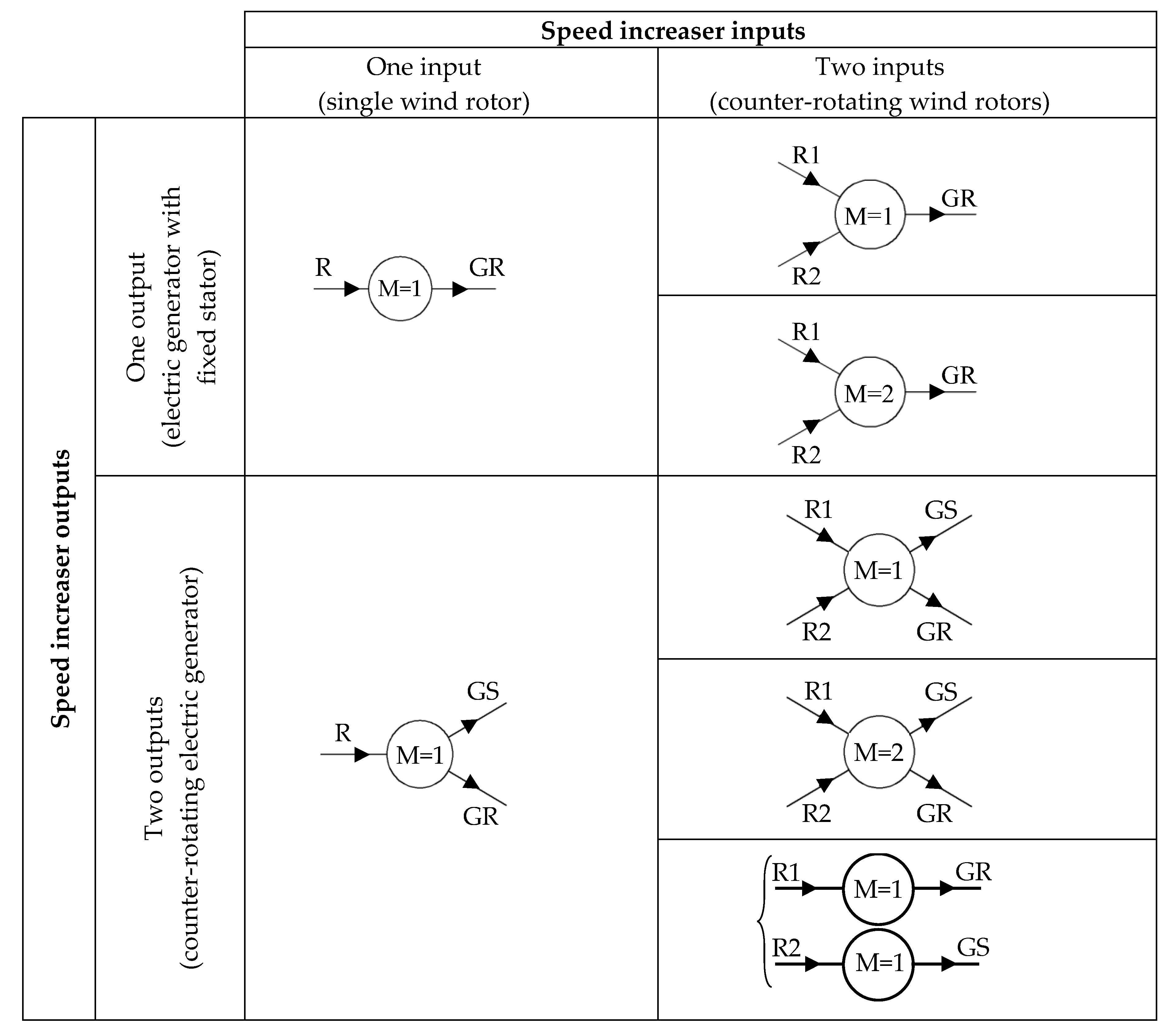
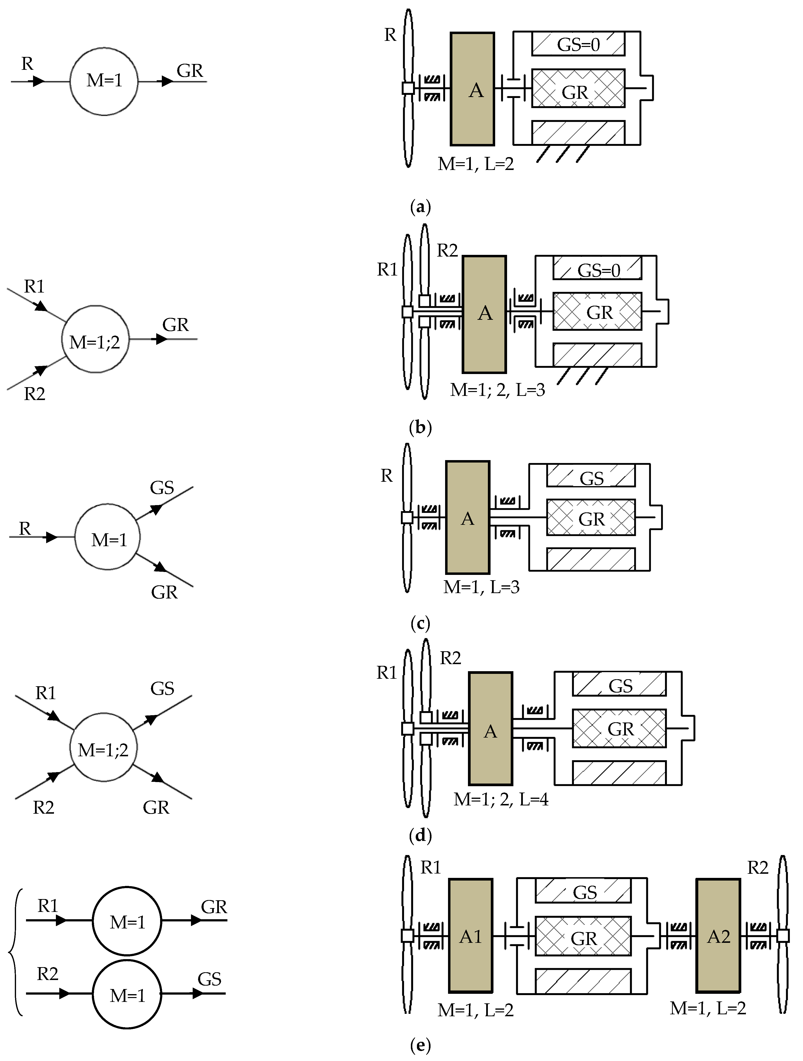
- The WT uses an electric generator with fixed stator (generator stator (GS) = 0) that is driven by one of the following solutions, Figure 5a,b:
- (a)
- (b)
- two counter-rotating wind rotors, R1 and R2, are connected to the generator rotor, GR, through a one DOF [50] or a two DOF [16,23,26,29,30,31,32,51] speed increaser, A (Figure 5b). R1 is considered the main rotor, always interconnected with the GR. In the first case (M = 1), R2 provides an additional input torque, while in the second case (M = 2), R2 contributes to increasing the output speed.
- The WT uses a counter-rotating electric generator (both GR and GS are mobile and rotate in opposite directions), Figure 5c–e:
- (a)
- (b)
- (c)
- (1)
- one or two wind rotors.
- (2)
- one DOF speed increasers with one input and one output (L = 2) or two outputs (L = 3, where L is the number of inputs and outputs) or two inputs (L = 3—one output, L = 4—two outputs), and/or two DOF speed increasers with one output (L = 3) or two outputs (L = 4).
- (3)
- an electric generator with fixed or mobile stator.
- the conversion systems without a speed increaser usually have a reduced capacity as the wind rotor speed must be compatible with the generator speed (which has a special construction that allows lower operating speeds than usual, and low electric power, implicitly).
- the gearbox (speed increaser) size and complexity increase with the multiplication ratio and power increase.
- the use of two counter-rotating wind rotors allows higher output power at the generator, either by summing up the input motions in the case of two DOF speed increasers or by summing up the torques in the case of one DOF speed increasers.
- the systems using counter-rotating generators (where both rotor and stator are mobile) allow either the reduction of the multiplication ratio or a decrease in the rotor(s) input speed(s).
- the use of a multi-stage gearbox with a high-speed generator increases both complexity and cost of the conversion system, but the system is compact for higher multiplication ratios, whereas the use of a single-stage transmission reduces complexity, but the size and weight of the conversion system increases with the multiplication ratio.
4. Conceptual Synthesis of Speed Increasers for Wind Turbines
- Structural specifications:
- -
- number of wind rotors: one or two.
- -
- simple or complex gear transmission as a speed increaser; a simple transmission contains one satellite carrier, while the complex transmission has at least two distinct carriers.
- -
- electric generator with fixed or mobile stator.
- Geometric, constructive and kinematic specifications used in the rough evaluation:
- -
- the same radial size of the speed increaser in any solving variant.
- -
- lower size of the intermediary gears for a minimal inertial effect.
- -
- imposed ratio of the largest gear and smallest gear radii.
- -
- reduced structural complexity and simpler construction of the conversion system.
- -
- increased multiplication ratio of the speed increaser.
- Kinematic, static, dynamic and constructive specifications for the selection of the concept:
- -
- imposed multiplication ratio of the speed increaser (10 ± 0.5% for the analyzed case study).
- -
- highest efficiency of the speed increaser.
- -
- highest mechanical power on the generator shaft.
- -
- smallest axial size of the speed increaser.
- -
- complexity degree of the conversion system as low as possible.
4.1. Qualitative Solving Variants for Speed Increasers
4.2. Selection of the Representative Qualitative Solving Variants
- all speed increasers have the same radial size.
- the speed diagrams are built considering that the ratio between the largest gear radius and the smallest gear radius is equal to six.
- the input speed is considered equal to one.
- in the case of the solutions depicted in Figure 6f,g, the speeds of the two counter-rotating wind rotors are considered equal but in opposite directions; therefore, the ratio () of the input speeds is: .
- in the case of the solutions with counter-rotating outputs, the equivalent speed of an electric generator with fixed stator will be further used in the selection process: (i.e., the relative speed between the generator rotor and stator).
- as the input speed is equal to one, the multiplication ratio () of the speed increaser is given by the output speed (), the sign “−/+” indicating that the GR is rotating in the opposite/same direction to the main rotors, R1/R.
- C 1 = multiplication ratio, which must be as high as possible;
- C 2 = the size of the intermediate gears has to be as low as possible to have a minimal inertial effect;
- C 3 = simpler construction.
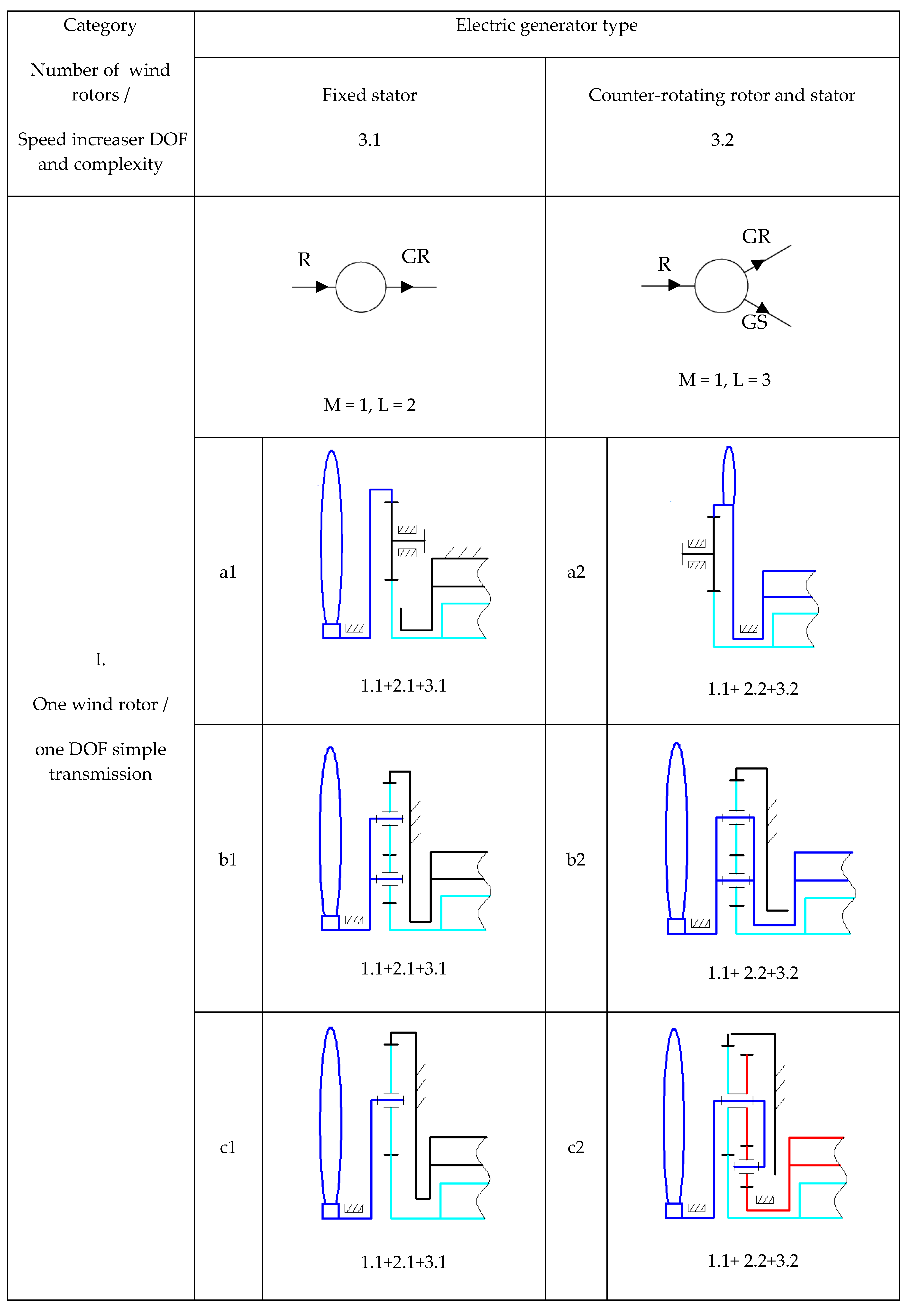
- Category I—the conversion system containing a single wind rotor, a simple transmission and a generator with a fixed or mobile stator: the scheme from Figure 6b has the highest absolute value of the transmission multiplication ratio of this category for both functioning cases (fixed or mobile generator stator)—3 (L = 2)/6 (L = 3); the speed increaser can be with one or two outputs (one DOF, L = 2/one DOF, L = 3).
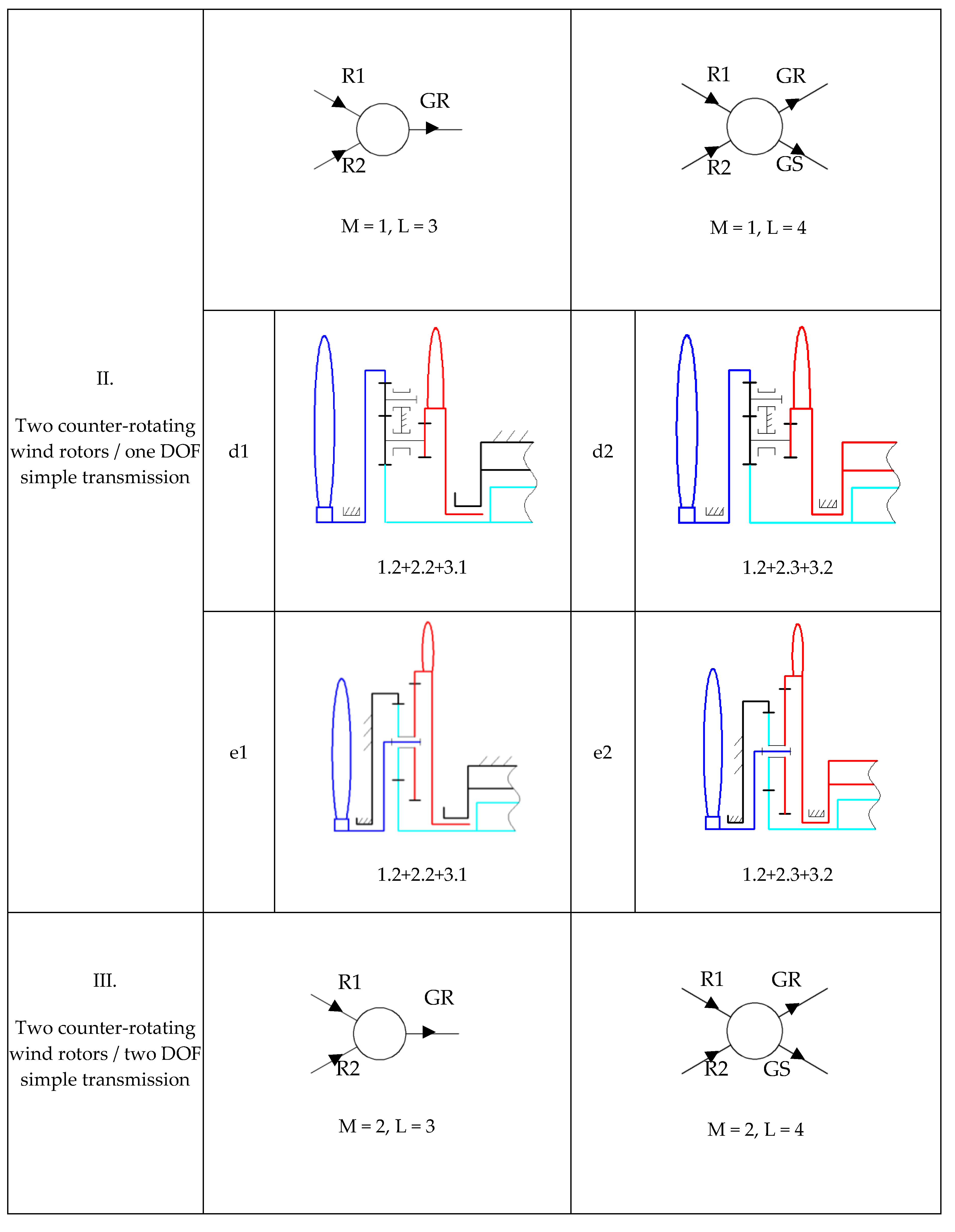
- Category II—the conversion system containing two counter-rotating rotors, a one DOF simple transmission and a generator with a fixed or mobile stator: the variant illustrated in Figure 6e is the representative solution of this category; it contains a gearbox with a multiplication ratio of 3.76/6.72 and a simple construction for the two functioning cases—one DOF, L = 3 (two inputs and one output); one DOF, L = 4 (two inputs and two outputs).
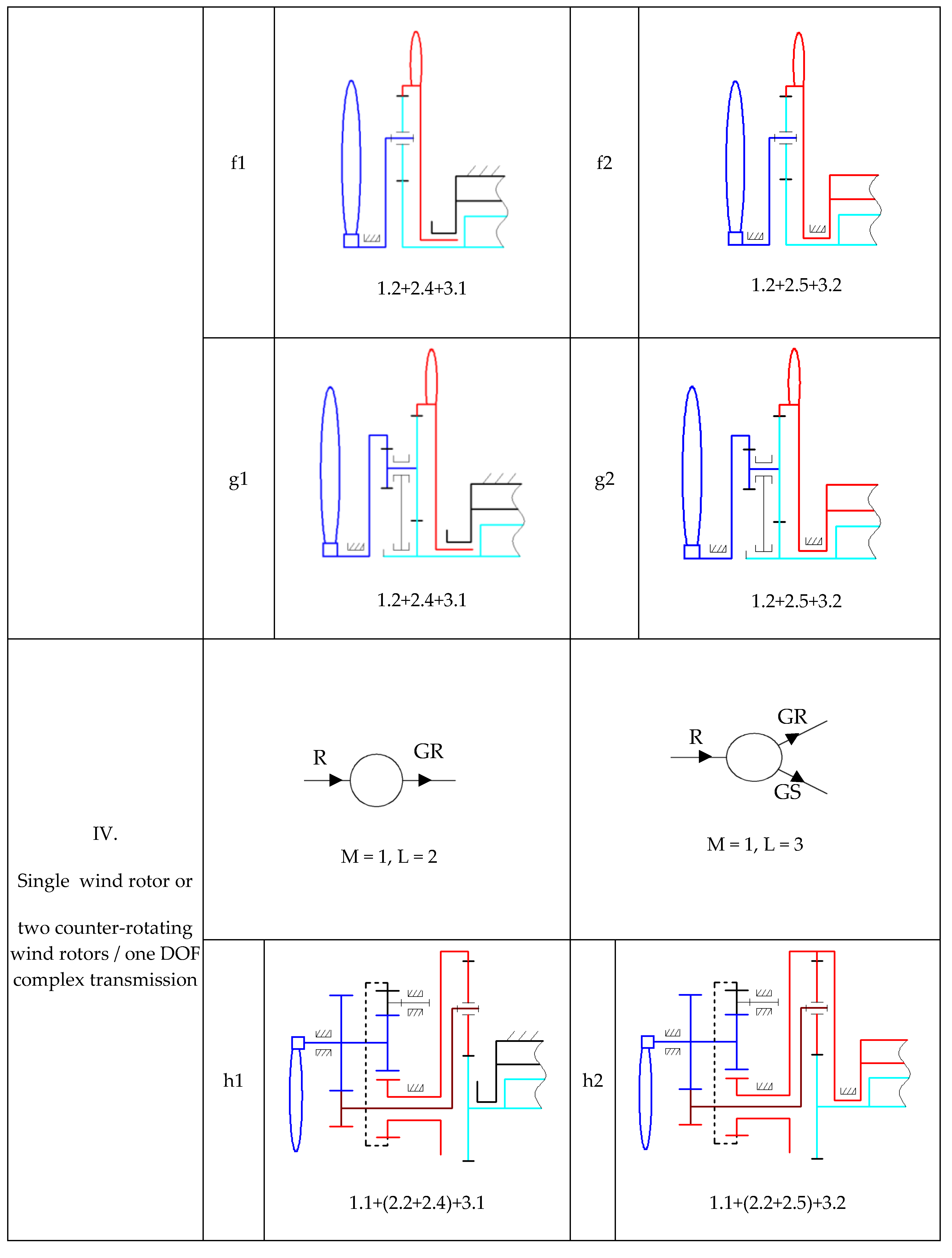
- Category III—the conversion system containing a single wind rotor, a two DOF simple transmission and a generator with a fixed or mobile stator: the variant from Figure 6g is the representative solution of the third category; the transmission allows a higher multiplication ratio of 29.87/38.89 for the two functioning situations—two DOF, L = 3 (two inputs and one output); two DOF, L = 4 (two inputs and two outputs).
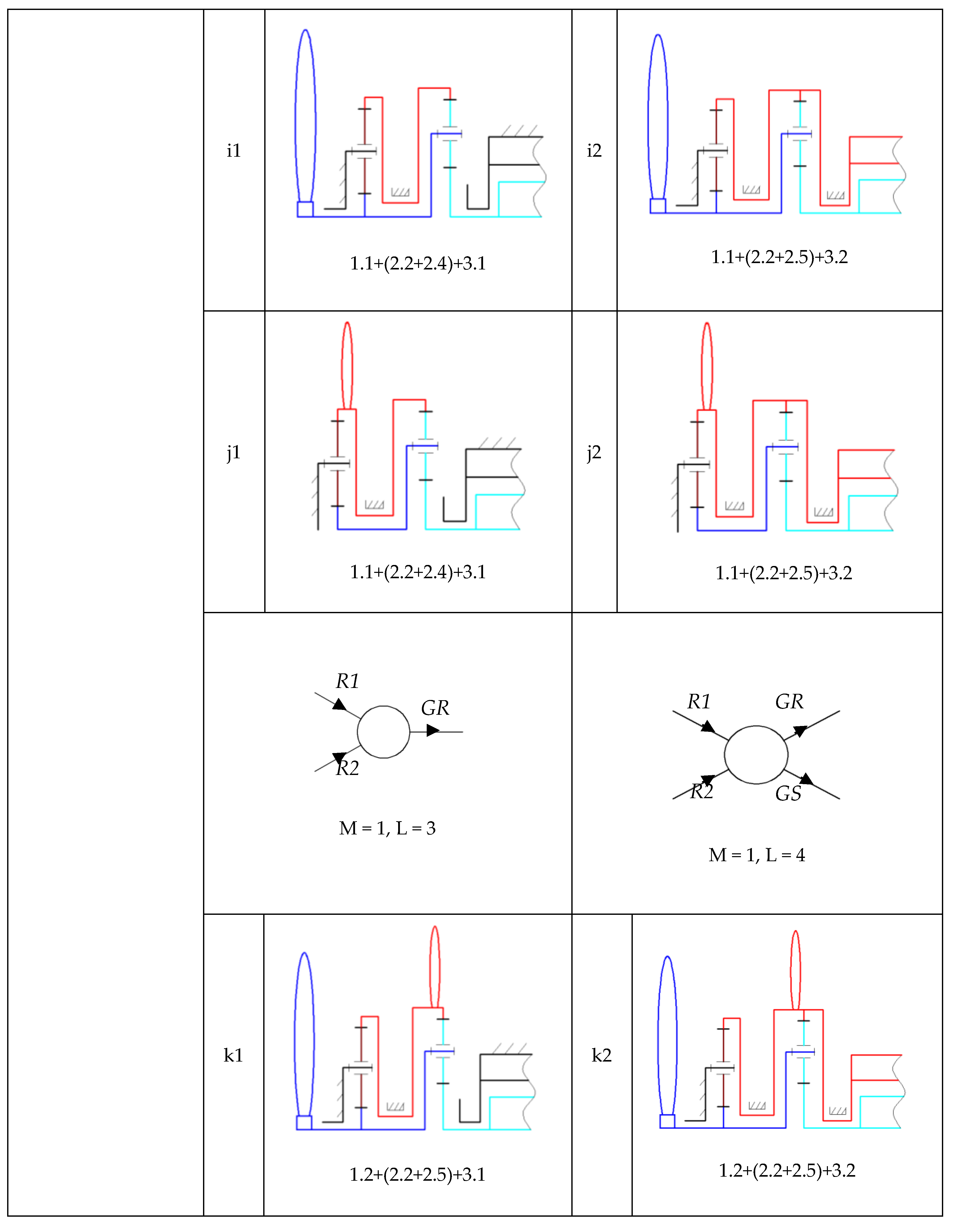
- Category IV—the conversion system containing one or two rotors, a one DOF complex transmission and a generator with a fixed or mobile stator: the scheme from Figure 6j is the representative solution in terms of multiplication ratio; the transmission is characterized by a multiplication ratio of 6.42/13.71 for the two functioning situations—one DOF, L = 2 (one input, one output) and L = 3 (one input, two outputs)/one DOF, L = 3 (two inputs, one output) and L = 4 (two inputs, two outputs).
4.3. Quantitative Solving Variants of Speed Increasers: A Case Study
4.3.1. Quantitative Evaluation of the Representative Qualitative Solving Variants
- the speed increaser multiplication ratio: ;
- the radial dimension of the gearbox is imposed by limiting the number of teeth of the biggest gear: ;
- the efficiency of a gear pair: .
- (a)
- Representative solving variant (RSV) 1 (Figure 6b)
- (b)
- RSV 2 (Figure 6e), for which is considered the case
- (c)
- RSV 3 (Figure 6g), in the premise
- (d)
- RSV 4 (Figure 6j)
4.3.2. Results and Discussions
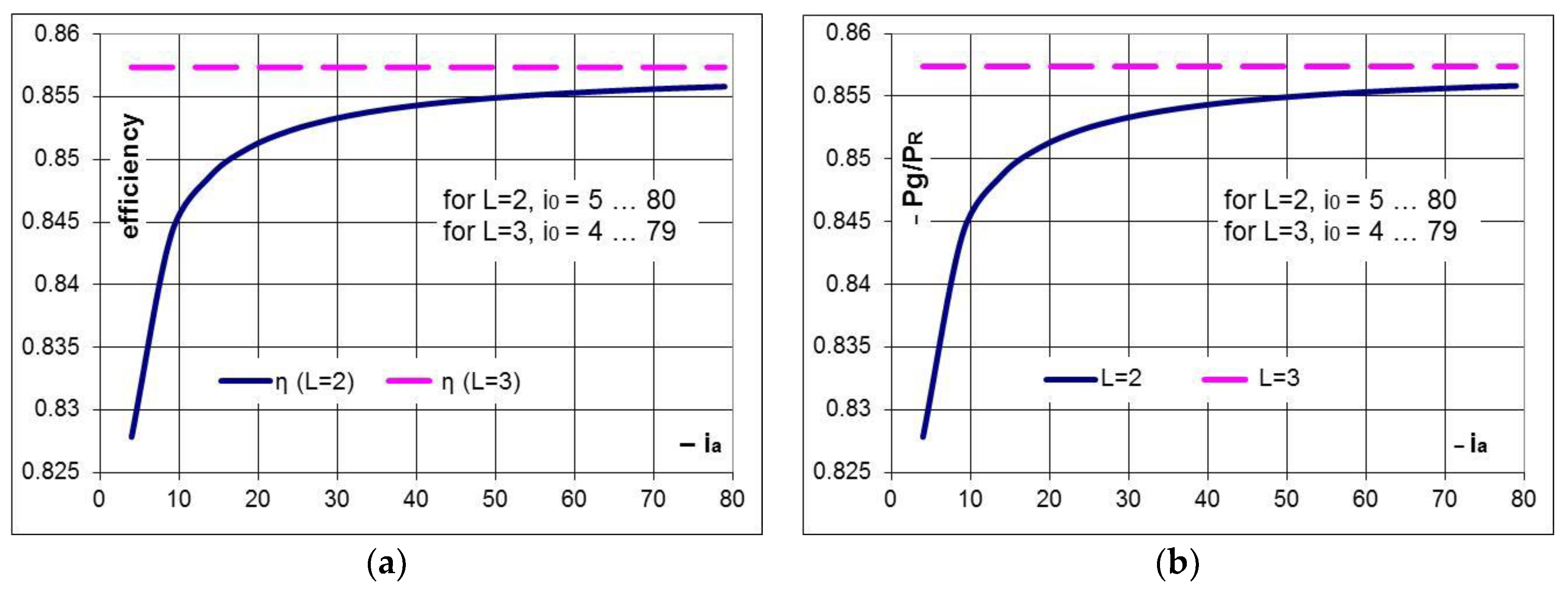
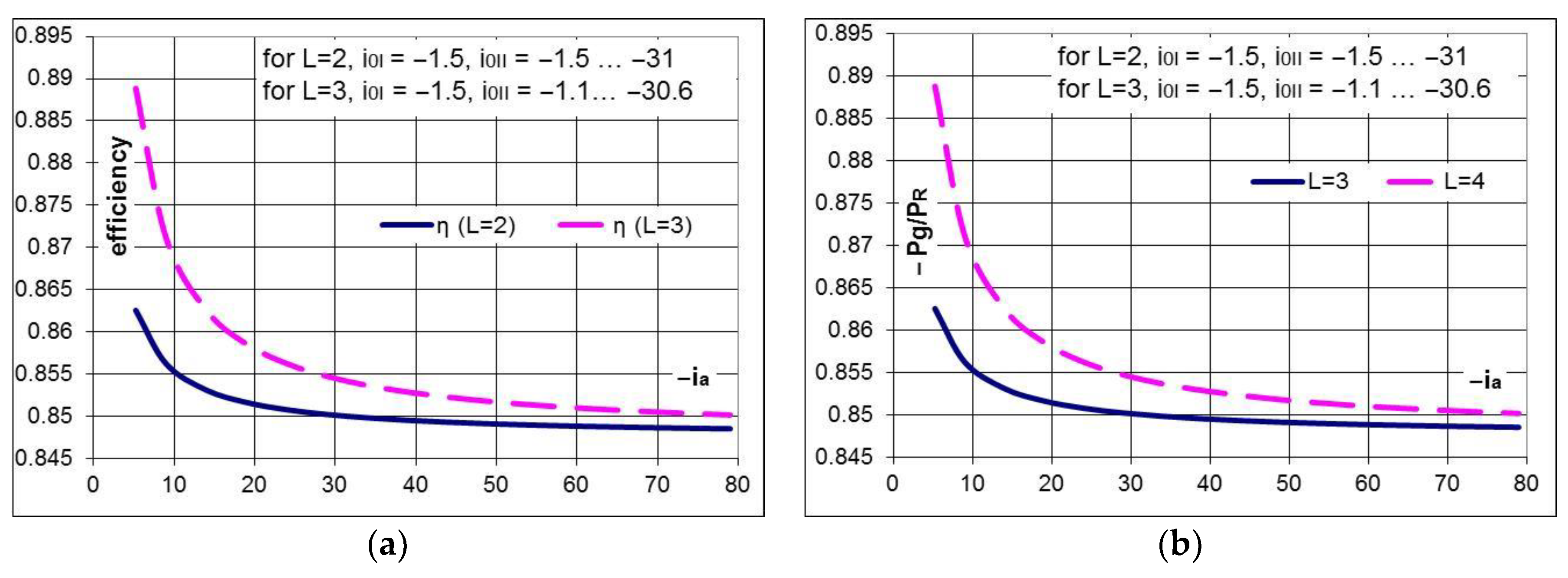
- the efficiency of the gearbox with L = 2 and a fixed stator generator is steadily rising towards the interior efficiency () with the increase of the absolute value of the multiplication ratio () (Figure 11a).
- the system with L = 3 (containing a generator with mobile and counter-rotating stator and rotor) is characterized by the following advantages compared to the conversion system with one input and one output (L = 2).
- the gearbox efficiency is constant and equal to , not being influenced by the transmission interior kinematic ratio; therefore, the case with L = 3 is preferred to the system with L = 2 for small–medium values of the multiplication ratio ( < 30); for instance, for and the efficiencies are and , which lead to a relative increase of the efficiency of the L = 3 case with approximately 1.4%, versus the L = 2 system, and, therefore, a higher mechanical power of the counter-rotating generator (Figure 11a).
- the increase with one unit of the relative speed between the rotor and stator of the counter-rotating generator (L = 3) brings a significant contribution to the multiplication ratio in the medium range; for instance, the multiplication ratio for is in the case L = 2, and in the case L = 3, leads to a relative increase with 33% of the multiplication ratio for the same gearbox type. Thus, for the same multiplication ratio, the case L = 3 allows the decrease of the interior kinematic ratio and of the radial dimension, implicitly, or a smaller input speed is required when using the same gearbox and the same relative speed in the counter-rotating generator (Figure 7); additionally, in the case L = 3 (Figure 11b), the generator input power () and its output electric power, implicitly, are higher at the same input power of the conversion system.
- for the same input torque , the torque on the generator shaft is lower in the case L = 3, , the differences between the two values being higher at smaller interior kinematic ratios. For instance, for and , the torque on the generator shaft in the case L = 3 is smaller by approximately 9% and the speed is higher by approximately 11% compared to the case L = 2; therefore, for the same wind power, the electric power generated by the conversion system in the case L = 3 (Figure 11b) is higher by approximately 1.4% than in the case L = 2, meaning that the counter-rotating generator starts sooner to produce energy than in the other case, as it has to overcome a smaller resistance.
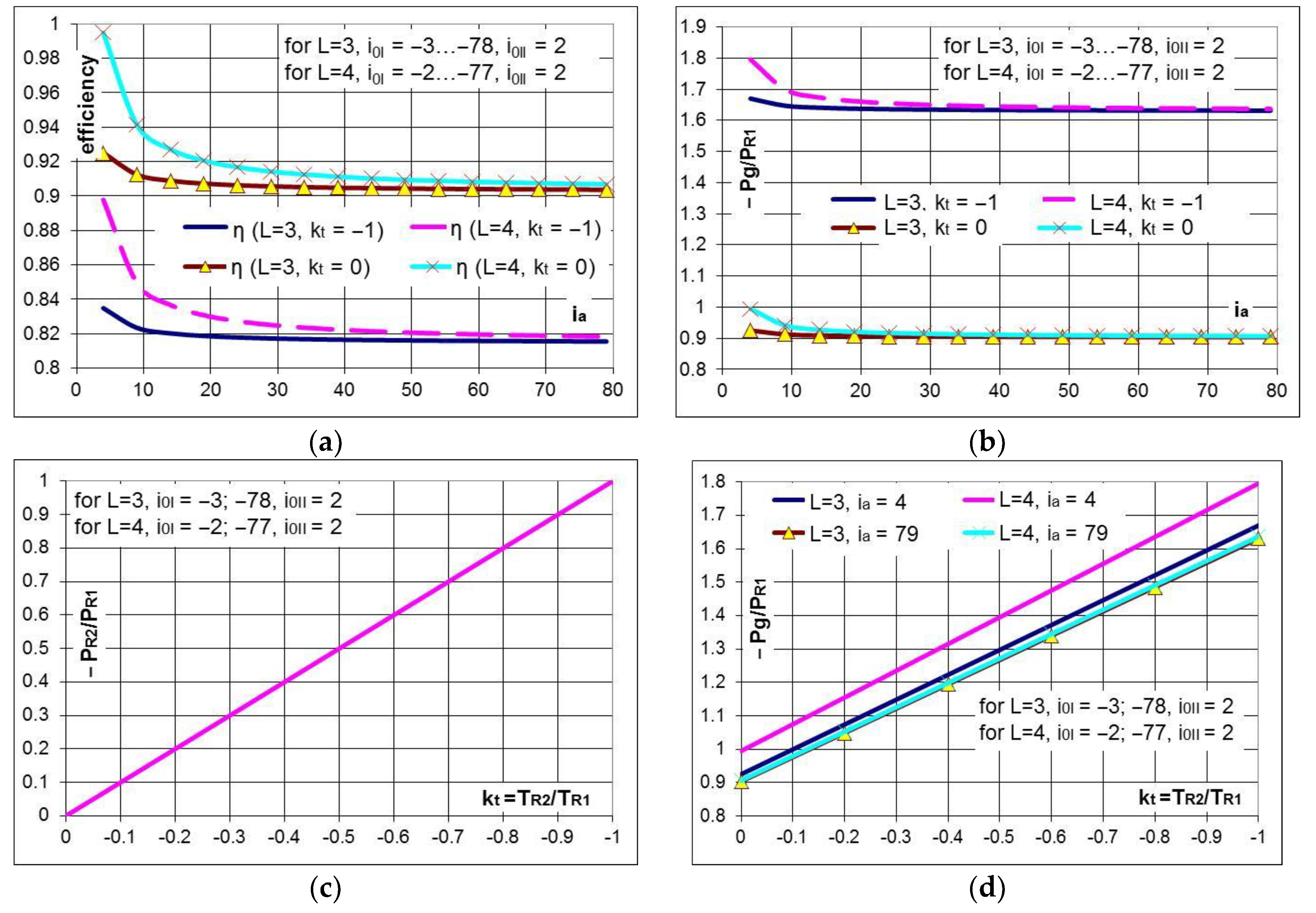
- for , the secondary rotor (R2) becomes the main rotor, which is less viable from a functional point of view; therefore, the case is further considered.
- the gearbox efficiency is strongly influenced by the ratio , obtaining higher values of the efficiency for lower absolute values of this ratio; the efficiency decreases with the increase of the torque generated by R2 (Figure 12a); if the input torques on the two rotors are equal in absolute values (), the gearbox efficiency (Figure 12a) and the input power on the generator shaft, which is due to R1 (Figure 12b), decreases by approximately 10% relative to the case in which the torque given by the secondary rotor is null ().
- the advantage of higher efficiency of the solutions with a mobile stator relative to the fixed stator case is practically insignificant for higher values of the multiplication ratio () (Figure 12).
- the mechanical power provided by the secondary rotor generates an increase in electric power, which can reach up to approximately 80% (Figure 12b) when the torque of the secondary rotor becomes equal to the torque given by the main rotor ().
- the system with L = 4 (two inputs and two outputs) has the following advantages compared to the system with L = 3 (2 inputs and 1 output): the efficiency of the L = 4 speed increaser is higher to that of the L = 3 transmission, regardless of the value of input torques ratio (). For the same ratio (), the differences between the efficiency values are higher with up to 6% for low multiplication ratios and decrease with the increase of the multiplication ratio; for instance, the difference between efficiency values reaches approximately 3% for (Figure 12a), which implies a slight increase in the output mechanical power that justifies the use of a counter-rotating generator (L = 4).
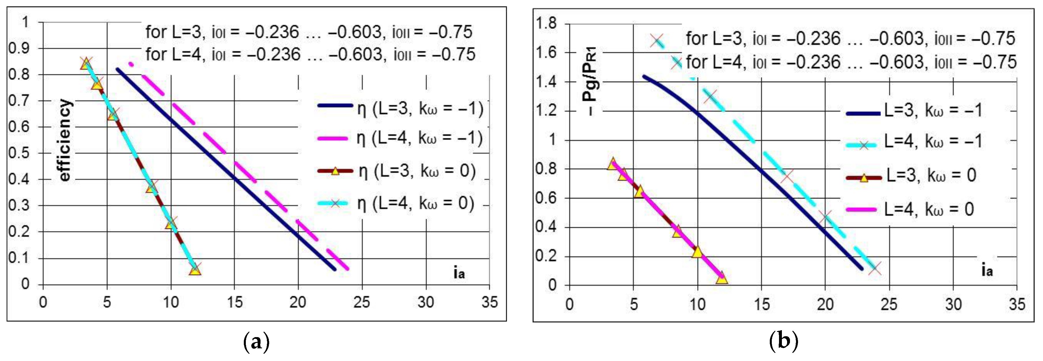
- R2 becomes the main rotor for , which is not viable from a functional point of view; therefore, the case is further analyzed.
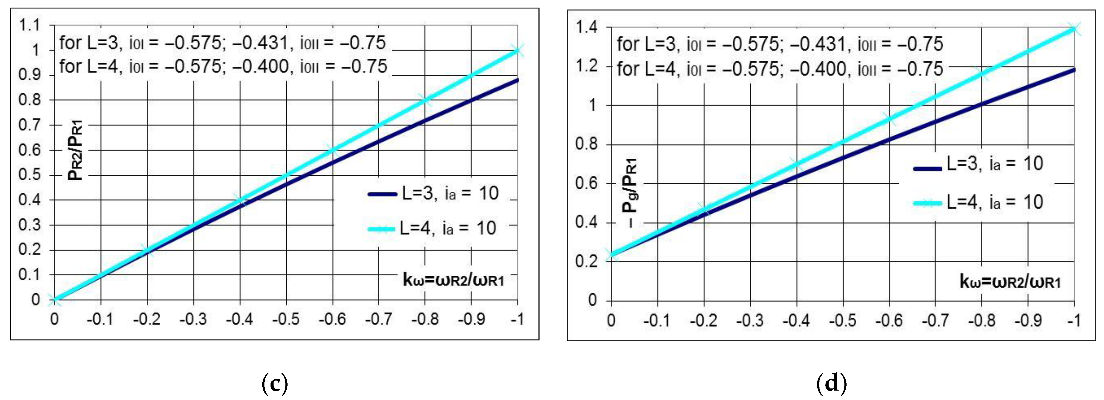
- the efficiency of the gearbox increases with the increase of the ratio for the same multiplication ratio (). For instance, considering and L = 3, the efficiency almost triples in the case () compared to the case () (Figure 13a).
- the efficiency values decrease with an increase in the multiplication ratio by a higher gradient as the module of the kω ratio is lower. Thus, these gearboxes can be implemented in wind turbines of medium and low power (with low multiplication ratios).
- the gearbox efficiency decreases with the increase of the multiplication ratio (Figure 13a).
- the conversion system with L = 4 has the following advantages compared to the system with L = 3:
- -
- the solution containing a generator with a mobile stator (L = 4) ensures the efficiency increase with the increase of the ratio ; for instance, for , the efficiency in the case L = 4 is higher by approximately 10% to the case L = 3, regardless of the value of the multiplication ratio () (Figure 13a).
- -
- due to the relatively good efficiencies, the solution can be applied to systems characterized by high absolute values of the multiplication ratio and limited radial dimensions; in these cases, a higher speed of the generator can be obtained by using two or more planetary gear trains as a speed increaser (Figure 10).
- the system with L = 3, containing a counter-rotating generator has the advantage of a higher efficiency compared to the system with L = 2; this advantage becomes insignificant for higher values of the multiplication ratio:
- -
- -
- the variant with L = 2, containing a fixed stator generator achieves lower efficiencies and mechanical power but close to those of the mobile stator solutions (L = 3) for high absolute values of the multiplication ratio, the difference being approximately 1% (Figure 14); therefore, in these cases, the fixed stator variant is recommended to be used.
4.4. Selection of the Conceptual Solution
- CA: Highest mechanical power of the generator;
- CB: Highest efficiency of the speed increaser;
- CC: Smallest axial size of the gearbox;
- CD: Degree of complexity as low as possible.
5. Conclusions and Recommendations
- (a)
- the degree of freedom (one or two DOF).
- (b)
- the number of inputs: one or two wind rotors.
- (c)
- the number of outputs: one output (electric generator with a fixed stator) or two outputs (mobile and counter-rotating rotors and a stator).
- (d)
- the number of external links (L), i.e., the sum of inputs and outputs.
- (e)
- the (minimum) multiplication ratio, defined as the ratio between the equivalent generator speed (rotational speed of the rotor relative to the stator) and the wind rotor speed (in the case of two rotors: the higher rotor speed).
- (f)
- the mechanical efficiency, defined as the ratio between the output and input mechanical powers.
- (g)
- the (structural and technological) degree of complexity.
- (a)
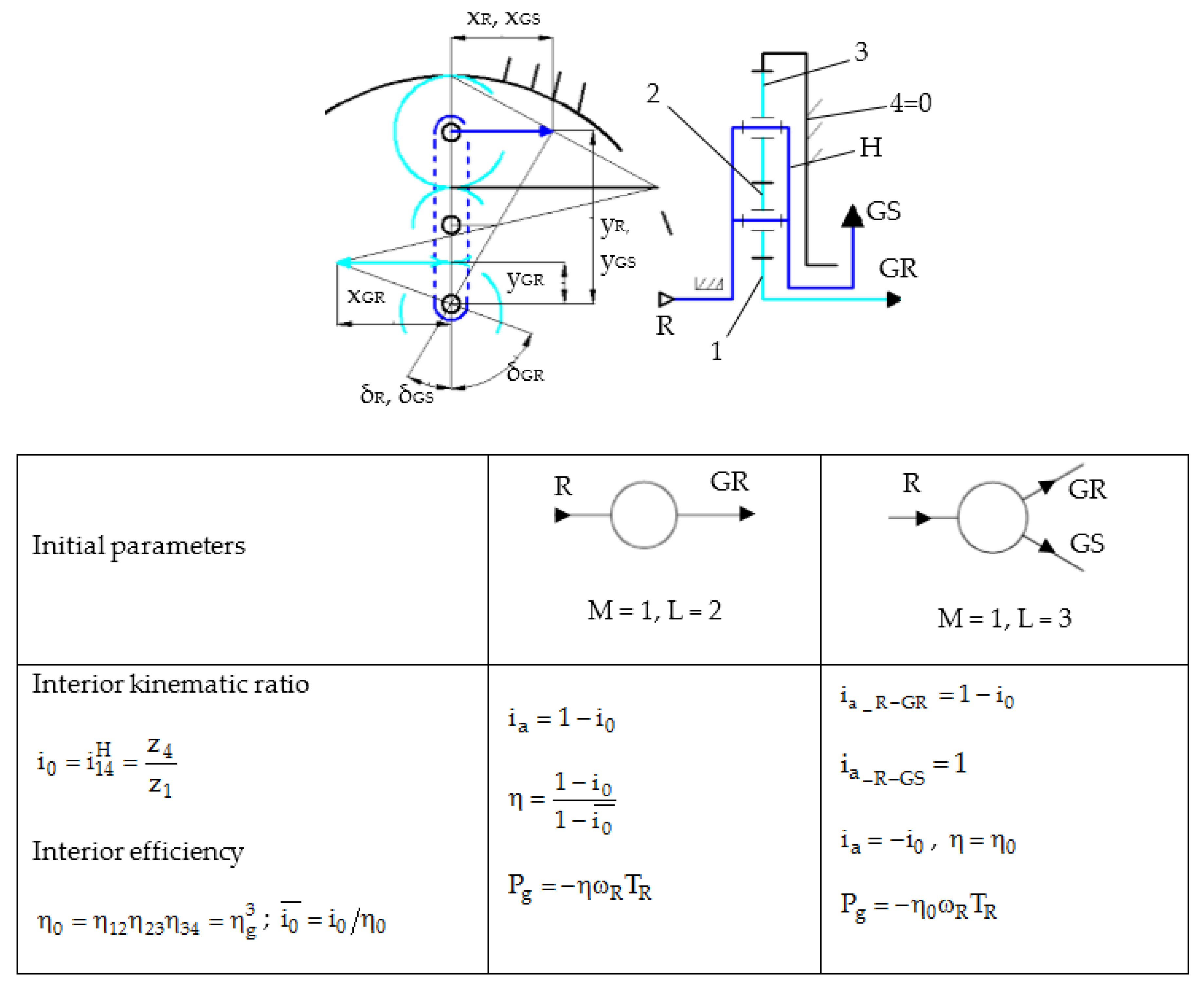
- one DOF speed increaser with one input and one output (generator rotor) (L = 2).
- (b)
- one DOF speed increaser with one input (single wind rotor) and two outputs (counter-rotating generator) (L = 3); the mechanical driving of the rotor and stator of the electric generator is in opposite directions with speeds that are inversely proportional to their mechanical moments of inertia.
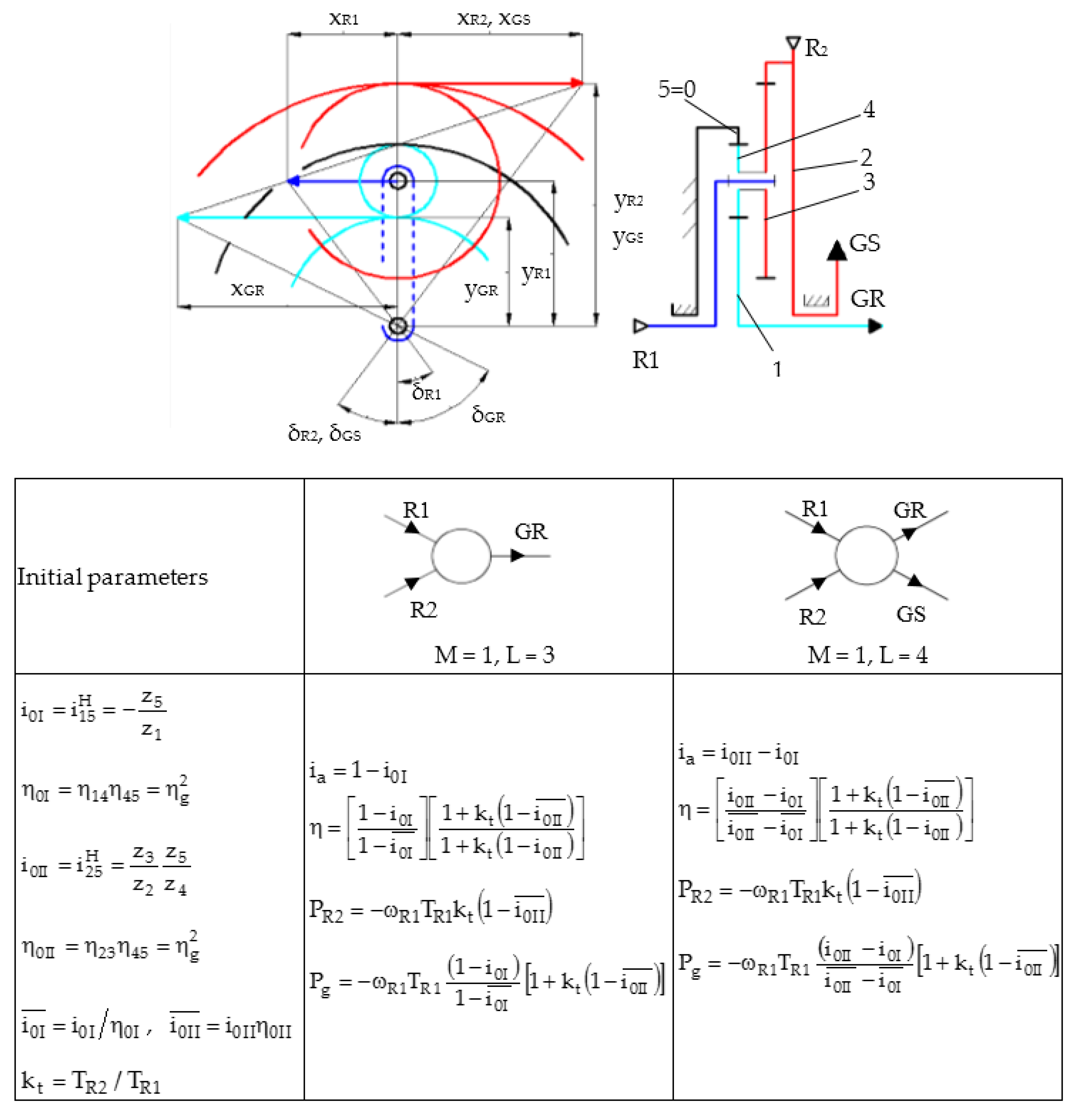
- (c)
- one DOF speed increaser with two inputs (counter-rotating wind rotors) and one output (generator rotor) (L = 3) and two independent torques; the mechanical summation of the two torsional torques (from the wind rotors) allows the increase of the output mechanical power.
- (d)
- one DOF speed increaser with two inputs (counter-rotating wind rotors) and two outputs (counter-rotating generator) (L = 4) and two independent torques.
- (e)
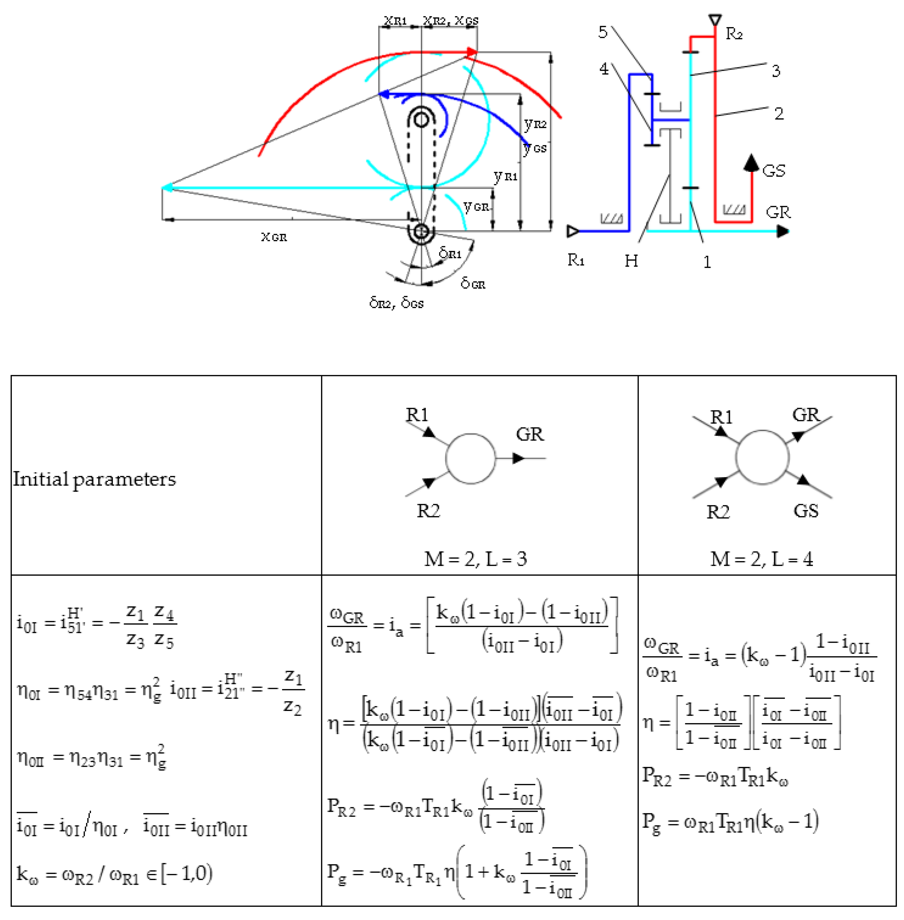
- two DOF speed increaser with two inputs (counter-rotating wind rotors) and one output (generator rotor) (L = 3) and two independent motions.
- (f)
- two DOF speed increaser with two inputs (counter-rotating wind rotors) and two outputs (counter-rotating generator) (L = 4) and two independent motions.
- (a)
- maximization of the speed increaser efficiency.
- (b)
- increase of the speed at the generator by:
- -
- using a counter-rotating generator
- -
- summing up the motions of two counter-rotating wind rotors with a two DOF planetary transmission as a speed increaser
- -
- branching out the wind rotor motion with the help of a one DOF transmission and summing up the obtained motions with a two DOF planetary transmission
- (c)
- increase of the torque on the generator shaft by summing up the torques of two counter-rotating rotors through a one DOF transmission.
- (d)
- combination of the above solutions.
- (a)
- the gearbox should be designed to be installed in a specific system that allows the conversion of the wind energy into electricity, based on the location and the implementation conditions.
- (b)
- if a speed increaser with a high multiplication ratio is requested, it is recommended to use a gearbox consisting of a one DOF planetary gear that allows branching out of the rotor speed, and a two DOF planetary gear that sums up the two motions, increasing the speed in this way (Figure 10).
- (c)
- although the use of a counter-rotating generator increases, to a certain extent, the complexity of the conversion system, the mobile stator of the generator adds additional speed and power, which becomes significant mainly for small and medium values of the multiplication ratio.
- -
- one DOF transmission that sums up the speeds of two rotors (Figure 6d1,d2,e1,e2,k1,k2).
- -
- two DOF transmission that sums up the speeds of two rotors (Figure 6f1,f2,g1,g2).
- -
- complex transmission containing a one DOF planetary gear, in which the motion of a rotor branches into two other motions, and a two DOF planetary gear, which sums up the two motions (Figure 6h1,h2,i1,i2,j1,j2).
Author Contributions
Funding
Conflicts of Interest
References
- Booker, J.D.; Mellor, P.H.; Wrobel, R.; Drury, D. A compact, high efficiency contra-rotating generator suitable for wind turbines in the urban environment. Renew. Energy 2010, 35, 2027–2033. [Google Scholar] [CrossRef]
- Lee, S.; Kim, H.; Son, E.; Lee, S. Effects of design parameters on aerodynamic performance of a counter-rotating wind turbine. Renew. Energy 2012, 42, 140–144. [Google Scholar] [CrossRef]
- Sapre, R.; Murkute, H.; Agrawal, R. Comparison between single axis wind turbine and counter wind turbine—A case study. Glob. J. Eng. Appl. Sci. 2012, 2, 144–146. [Google Scholar]
- Frost, W. Engineering Handbook on the Atmospheric Environmental Guidelines for Use in Wind Turbine Generator Development. NASA Technical Report no. 1359; 1978. Available online: https://ntrs.nasa.gov/search.jsp?R=19790006508 (accessed on 19 September 2017).
- Hau, E. Wind Turbines: Fundamentals, Technologies, Application, Economics, 2nd ed.; Springer: Berlin/Heidelberg, Germany, 2006; pp. 253–3018. ISBN 978-3-540-24240-6. [Google Scholar]
- Vișa, I.; Jaliu, C.; Duță, A.; Neagoe, M.; Comsit, M.; Moldovan, M.; Ciobanu, D.; Burduhos, B.; Saulescu, R. The Role of Mechanisms in Sustainable Energy Systems; Transilvania University of Brașov Publishing House: Brașov, Romania, 2015; pp. 218–316. ISBN 978-606-19-0571-3. [Google Scholar]
- Appa, K. Energy Innovations Small Grant (EISG) Program (Counter Rotating Wind Turbine System). EISG Final Report. 2002. Available online: http://www.eai.in/ref/invent/upload/00-09%2520FAR%2520Appendix%2520A.pdf (accessed on 11 June 2017).
- Jung, S.; No, T.; Ryu, K. Aerodynamic performance prediction of a 30 kW counter-rotating wind turbine system. Renew. Energy 2005, 30, 631–644. [Google Scholar] [CrossRef]
- McKenna, R.; Ostman, V.D.; Leye, P.; Fichtner, W. Key challenges and prospects for large wind turbines. Renew. Sustain. Energy Rev. 2016, 53, 1212–1221. [Google Scholar] [CrossRef]
- Lee, S.; Kim, H.; Lee, S. Analysis of aerodynamic characteristics on a counter-rotating wind turbine. Curr. Appl. Phys. 2010, 10, S339–S342. [Google Scholar] [CrossRef]
- Hwang, B.; Lee, S.; Lee, S. Optimization of a counter-rotating wind turbine using the blade element and momentum theory. J. Renew. Sustain. Energy 2013, 5, 052013. [Google Scholar] [CrossRef]
- Dong, W.; Xing, Y.; Moan, T. Time Domain Modeling and Analysis of Dynamic Gear Contact Force in a Wind Turbine Gearbox with Respect to Fatigue Assessment. Energies 2012, 5, 4350–4371. [Google Scholar] [CrossRef] [Green Version]
- Newman, B.G. Actuator-disc theory for vertical-axis wind turbines. J. Wind Eng. Ind. Aerodyn. 1983, 15, 347–355. [Google Scholar] [CrossRef]
- Farahani, E.M.; Hosseinzadeh, N.; Ektesabi, M. Comparison of fault-ride-through capability of dual and single-rotor wind turbines. Renew. Energy 2012, 48, 473–481. [Google Scholar] [CrossRef]
- No, T.S.; Kim, J.E.; Moon, J.H.; Kim, S.J. Modelling, control, and simulation of dual rotor wind turbine generator system. Renew. Energy 2009, 34, 2124–2132. [Google Scholar] [CrossRef]
- Climescu, O.; Jaliu, C.; Saulescu, R. Comparative Analysis of Horizontal Small Scale Wind Turbines for a Specific Application. In Proceedings of the 14th IFToMM World Congress, Taipei, Taiwan, 25–30 October 2015. [Google Scholar] [CrossRef]
- Kubo, K.; Hano, Y.; Mitarai, H.; Hirano, K.; Kanemoto, T.; Galal, A.M. Intelligent wind turbine unit with tandem rotors (discussion of prototype performances in field tests). Curr. Appl. Phys. 2010, 10, S326–S331. [Google Scholar] [CrossRef]
- Moghadassian, B.; Rosenberg, A.; Sharma, A. Numerical Investigation of Aerodynamic Performance and Loads of a Novel Dual Rotor Wind Turbine. Energies 2016, 9, 571. [Google Scholar] [CrossRef]
- Chantharasenawong, C.; Suwantragul, B.; Ruangwiset, A. Axial Momentum Theory for Turbines with Co-axial Counter Rotating Rotors. In Proceedings of the Commemorative International Conference of the Occasion of the 4th Cycle Anniversary of KMUTT Sustainable Development to Save the Earth: Technologies and Strategies Vision 2050: (SDSE2008), Bangkok, Thailand, 11–13 December 2008. [Google Scholar]
- Marjanovic, N.; Isailovic, B.; Marjanovic, V.; Milojevic, Z.; Blagojevic, M.; Bojic, M. A practical approach to the optimization of gear trains with spur gears. Mech. Mach. Theory 2012, 53, 1–16. [Google Scholar] [CrossRef]
- Bevingtoll, C.M.; Bywaters, G.L.; Coleman, C.C.; Costin, D.P.; Danforth, W.L.; Lynch, J.A.; Rolland, R.H. Wind Turbine Having a Direct-Drive Drivetrain. U.S. Patent No. 7431567B1, 7 October 2008. [Google Scholar]
- Mesquita, A.L.A.; Palheta, F.C.; Pinheiro Vaz, J.R.; Girão de Morais, M.V.; Gonçalves, C. A methodology for the transient behavior of horizontal axis hydrokinetic turbines. Energy Convers. Manag. 2014, 87, 1261–1268. [Google Scholar] [CrossRef]
- Neagoe, M.; Saulescu, R.; Jaliu, C.; Cretescu, N. Novel speed increaser used in counter-rotating wind turbines. New Adv. Mech. Mech. Transm. Robot. Mech. Mach. Sci. 2017, 46, 143–151. [Google Scholar] [CrossRef]
- Saulescu, R.; Neagoe, M.; Jaliu, C. Improving the energy performance of wind turbines implemented in the built environment using counter-rotating planetary transmissions. IOP Conf. Ser. Mater. Sci. Eng. 2016, 147, 012089. [Google Scholar] [CrossRef] [Green Version]
- Saulescu, R.; Neagoe, M.; Munteanu, O.; Cretescu, N. Performance analysis of a novel planetary speed increaser used in single-rotor wind turbines with counter-rotating electric generator. IOP Conf. Ser. Mater. Sci. Eng. 2016, 147, 012090. [Google Scholar] [CrossRef] [Green Version]
- Climescu, O.; Săulescu, R.; Jaliu, C. Specific features of a counter-rotating transmission for renewable energy systems. Environ. Eng. Manag. J. 2011, 10, 1105–1113. [Google Scholar]
- Saulescu, R.; Jaliu, C.; Neagoe, M. Structural and kinematic features of a 2 DOF speed increaser for renewable energy systems. Appl. Mech. Mater. 2016, 823, 367–372. [Google Scholar] [CrossRef]
- Saulescu, R.; Neagoe, M.; Jaliu, C.; Munteanu, O. Comparative analysis of two wind turbines with planetary speed increaser in steady-state. Appl. Mech. Mater. 2016, 823, 355–360. [Google Scholar] [CrossRef]
- Saulescu, R.; Jaliu, C.; Munteanu, O.; Climescu, O. Planetary gear for counter-rotating wind turbines. Appl. Mech. Mater. 2014, 658, 135–140. [Google Scholar] [CrossRef]
- Saulescu, R.; Jaliu, C.; Climescu, O.; Diaconescu, D. On the use of 2 DOF planetary gears as “speed increaser” in small hydros and wind turbines. In Proceedings of the ASME 2011 International Design Engineering Technical Conferences & Computers and Information in Engineering Conference, IDETC/CIE 2011, Washington, DC, USA, 28–31 August 2011; pp. 601–610, Paper No. DETC2011-47042. [Google Scholar] [CrossRef]
- Wacinski, A.; Sàrl, E. Drive Device for a Windmill Provided with Two Counter–Rotative Propellers. U.S. Patent No. 7384239B2, 10 June 2008. [Google Scholar]
- Herzog, R.; Schaffarczyk, A.P.; Wacinski, A.; Zürcher, O. Performance and stability of a counter–rotating windmill using a planetary gearing: Measurements and Simulation. EWEC 2010, 6, 4847. Available online: https://www.researchgate.net/publication/236683548 (accessed on 15 June 2017).
- Brander, M. Bi-Directional Wind Turbine. U.S. Patent US 2008/0197639 A1, 21 August 2008. [Google Scholar]
- Qiu, J.; Liu, B.; Dong, H.; Wang, D. Type Synthesis of Gear-box in Wind Turbine. Procedia Comput. Sci. 2017, 109C, 809–816. [Google Scholar] [CrossRef]
- Hall, J.F.; Mecklenborg, C.A.; Chen, D.; Pratap, S.B. Wind energy conversion with a variable-ratio gearbox: Design and analysis. Renew. Energy 2011, 36, 1075–1080. [Google Scholar] [CrossRef]
- Jelaska, D.; Podrug, S.; Perkusic, M. A novel hybrid transmission for variable speed wind turbines. Renew. Energy 2015, 83, 78–84. [Google Scholar] [CrossRef]
- Zhao, M.; Ji, J. Dynamic analysis of wind turbine gearbox components. Energies 2016, 9, 110. [Google Scholar] [CrossRef]
- Kanemoto, T.; Galal, A.M. Development of intelligent wind turbine generator with tandem wind rotors and double rotational armatures. JSME Int. J. Ser. B 2006, 49, 450–457. [Google Scholar] [CrossRef]
- Duong, M.Q.; Leva, S.; Mussetta, M.; Le, K.H. A Comparative Study on Controllers for Improving Transient Stability of DFIG Wind Turbines During Large Disturbances. Energies 2018, 11, 480. [Google Scholar] [CrossRef]
- Duong, M.Q.; Grimaccia, F.; Leva, S.; Mussetta, M.; Le, K.H. Improving Transient Stability in a Grid-Connected Squirrel-Cage Induction Generator Wind Turbine System Using a Fuzzy Logic Controller. Energies 2015, 8, 6328–6349. [Google Scholar] [CrossRef] [Green Version]
- Zhamalov, A.Z.; Obozov, A.D.; Kunelbaev, M.M.; Baikadamova, L.S. Capacity and Power Characteristics of Disk Generator with Counter-Rotation of Double-Rotor Wind Turbine. Middle-East J. Sci. Res. 2013, 15, 1655–1662. [Google Scholar] [CrossRef]
- Ribarov, L. Gearless Contra-Rotating Wind Generator. U.S. Patent US 2014/0008915, 9 January 2014. [Google Scholar]
- Cross, N. Engineering Design Methods: Strategies for Product Design; J. Wiley & Sons: New York, NY, USA, 2000; pp. 29–47. ISBN 978-0-471-87250-4. [Google Scholar]
- Ulrich, K.; Epinger, S. Product Design and Development, 4th ed.; McGraw-Hill, Inc.: New York, NY, USA, 2008; pp. 123–140. ISBN 978-007-125947-7. [Google Scholar]
- Pahl, G.; Beitz, W. Engineering Design. A Systematic Approach, 3rd ed.; Springer: London, UK, 2007; pp. 159–210. ISBN 987-1-84628-318-5. [Google Scholar]
- V.D.I. (Verein Deutscher Ingenieure)—Richtlinien 2221. Available online: https://www.vdi.de/nc/richtlinie/vdi_2221-methodik_zum_entwickeln_und_konstruieren_technischer_systeme_und_produkte/ (accessed on 15 November 2017).
- Diaconescu, D.; Neagoe, M.; Jaliu, C.; Saulescu, R. Products’ Conceptual Design; Transilvania University Publishing House: Brasov, Romania, 2010; pp. 140–160. ISBN 978-973-598-230-0. [Google Scholar]
- Jaliu, C.; Saulescu, R.; Diaconescu, D.; Neagoe, M. Conceptual design of a chain speed increaser for small hydropower stations. In Proceedings of the ASME 2009 International Design Eng. Technical Conf. & Computers and Information in Engineering Conf. IDETC/CIE 2009, San Diego, CA, USA, 30 August–2 September 2009; pp. 321–328. [Google Scholar] [CrossRef]
- Walliser, J. Wind Turbine Gear Mechanism. U.S. Patent US 2014/0128213A1, 8 May 2014. [Google Scholar]
- Schellstede, H. Wind Turbine Installation and Advance Double Counter-Rotating Blades, 90 Degree Drive Assembly with Lower Generator Mounting System. U.S. Patent US 2014/0015255 A1, 1 January 2014. [Google Scholar]
- Shinn, C.; Hur, M.C. Over–Drive Gear Device. U.S. Patent US 5222924, 29 June 1993. [Google Scholar]
- Kirschbaum, H. Wind Turbine-Generator. U.S. Patent US 4291233A, 22 September 1981. [Google Scholar]
- Caiozza, J. Wind Driven Electric Generator Apparatus. U.S. Patent US 7227276 B2, 5 June 2007. [Google Scholar]
- Winderl, W. Wind Operated Generator. U.S. Patent US 4039848A, 2 August 1977. [Google Scholar]
- Neagoe, M.; Săulescu, R.; Jaliu, C.; Munteanu, O.; Crețescu, N. Monomobile Counter-Rotating Wind Turbine. Patent RO A/00539/29.07.2016; in press (In Romanian).
- Sǎulescu, R.; Neagoe, M.; Vișa, M.; Jaliu, C.; Munteanu, O.; Totu, I.; Cretescu, N. Monomobile Planetary Speed Increaser with Two Counter-Rotating Outputs. Patent RO A/00905/25.11.2016; in press (In Romanian).
- Sǎulescu, R.; Neagoe, M.; Jaliu, C. Differential Planetary Speed Increaser with Two Counter-Rotating Outputs. Patent RO A/00326/30.05.2017; in press (In Romanian).
- Sǎulescu, R.; Neagoe, M.; Jaliu, C. Monomobile Planetary Speed Increaser with Two Inputs and Two Outputs. Patent RO A/00880/27.10.2017; in press (In Romanian).
- Miloiu, G.; Dudita, F.L.; Diaconescu, D. Modern Mechanical Transmissions, 2nd ed.; Tehnica Publishing House: Bucureşti, Romania, 1980; pp. 191–253. (In Romanian) [Google Scholar]


| Speed | ωR = ωR1 | |||||||||||
|---|---|---|---|---|---|---|---|---|---|---|---|---|
| Category Figure 6 | Min | Max | Min | Max | Min | Max | Min | Max | Min | Max | ||
| 1 | 2 | 3 | 4 | 5 | 6 | 7 | 8 | 9 | 10 | 11 | ||
| I. | a | +1 | - | - | −1.5 | −6 | +1 | +1 | −1.5 | −6 | −2.5 | −7 |
| b | - | - | −2 | −5 | +1 | +1 | −2 | −5 | −3 | −6 | ||
| c | - | - | +2.66 | +7 | −0.41 | −2.51 | +2.66 | +7 | +3.08 | +9.51 | ||
| II. | d | −0.83 | −1.14 | +1.86 | +5.92 | −0.83 | −1.14 | +1.86 | +5.92 | +2.69 | +7.06 | |
| e | −0.63 | −0.72 | +3.12 | +6 | −0.63 | −0.72 | +3.12 | +6 | +3.76 | +6.72 | ||
| III. | f | −1 | −1 | +4 | +13 | −1 | −1 | +4 | +13 | +5 | +14 | |
| g | −1 | −1.01 | +28.87 | +37.88 | −1 | −1.01 | +28.87 | +37.88 | +29.87 | +38.89 | ||
| IV. | h | - | - | +4 | +23 | −1 | −1.49 | +4 | +23 | +5 | +24.49 | |
| i | - | - | +3.45 | +13.25 | −0.63 | −1.04 | +3.45 | +13.25 | +4.09 | +14.29 | ||
| j | - | - | −5.42 | −12.71 | +1 | +1 | −5.42 | −12.71 | −6.42 | −13.71 | ||
| k | −0.63 | −1.04 | +3.45 | +13.25 | −0.63 | −1.04 | +3.45 | +13.25 | +4.09 | +14.29 | ||
| Figure 6 | I. | II. | III. | IV. | ||||||||
|---|---|---|---|---|---|---|---|---|---|---|---|---|
| Criterion | a | b | c | d | e | f | g | h | i | j | k | |
| C 1 | 9 | 8 | 10 | 10 | 9 | 6 | 10 | 10 | 7 | 7 | 7 | |
| C 2 | 7 | 10 | 7 | 9 | 8 | 9 | 8 | 9 | 9 | 9 | 10 | |
| C 3 | 10 | 9 | 6 | 7 | 10 | 10 | 8 | 5 | 9 | 10 | 8 | |
| 26 | 27 | 23 | 26 | 27 | 25 | 26 | 24 | 25 | 26 | 25 | ||
| Place | 2 | 1 | 3 | 2 | 1 | 2 | 1 | 3 | 2 | 1 | 2 | |
| Representative Solving Variants | RSV 1 | RSV 2 | RSV 3 | RSV 4 | |
|---|---|---|---|---|---|
| Figure | 7 | 8 | 9 | 10 | |
| Characteristics | |||||
| Number of teeth and the interior kinematic ratio | z1 = 40 z2 = 90 z3 = 90 z4 = 400 i0 = 10 | z1 = 36 z2 = 400 z3 = 225 z4 = 139 z5 = 314 i0I = −8.72 i0II =1.27 | z1 = 300 z2 = 400 z3 = 50 z4 = 25 z5 = 375 i0I = −0.4 i0II = −0.75 | z1 = 296 z2 = 32 z3 = 360 z4 = 400 z5 = 143 z6 = 114 i0I = −1.21; i0II = −3.5 | |
| Multiplication ratio | −10 | 9.993 | 10 | −9.992 | |
| Efficiency of a gear pair | 0.95 | 0.95 | 0.95 | 0.95 | |
| Representative Solving Variant | RSV 1 | RSV 2 | RSV 3 | RSV 4 | |
|---|---|---|---|---|---|
| Figure | 7 | 8 | 9 | 10 | |
| Characteristics | |||||
| Multiplication ratio | −10 | 9.993 | 10 | −9.992 | |
| Efficiency of a gear pair ηg | 0.95 | 0.95 | 0.95 | 0.95 | |
| Efficiency of the speed increaser | 0.857 | 0.845–0.937 | 0.237–0.696 | 0.87 | |
| Mechanical power at the generator input [kW] | 0.857 | 1.69–0.937 | 1.39–0.237 | 0.87 | |
| k | Criterion | CA | CB | CC | CD | Pk | Lk | Sk | Wk | wk |
|---|---|---|---|---|---|---|---|---|---|---|
| 1 | CA | 0.5 | 1 | 1 | 1 | 3.5 | 1 | 3 | 20 | 0.805 |
| 2 | CB | 0 | 0.5 | 1 | 1 | 2.5 | 2 | 2 | 3.5 | 0.140 |
| 3 | CC | 0 | 0 | 0.5 | 1 | 1.5 | 3 | 1 | 1.14 | 0.046 |
| 4 | CD | 0 | 0 | 0 | 0.5 | 0.5 | 4 | 0 | 0.2 | 0.009 |
| 24.84 | 1 | |||||||||
| RSV 1 | RSV 2 | RSV 4 | |||||
|---|---|---|---|---|---|---|---|
| Criterion | wk | Nk | wk·Nk | Nk | wk·Nk | Nk | wk·Nk |
| CA | 0.805 | 6 | 4.83 | 10 | 8.050 | 7 | 5.635 |
| CB | 0.140 | 8 | 1.12 | 10 | 1.400 | 9 | 1.260 |
| CC | 0.046 | 10 | 0.46 | 9 | 0.414 | 8 | 0.368 |
| CD | 0.009 | 10 | 0.09 | 9 | 0.081 | 7 | 0.063 |
| 34 | 6.5 | 38 | 9.945 | 31 | 7.326 | ||
| Place: |  | 3 | | 1 | | 2 | |
© 2018 by the authors. Licensee MDPI, Basel, Switzerland. This article is an open access article distributed under the terms and conditions of the Creative Commons Attribution (CC BY) license (http://creativecommons.org/licenses/by/4.0/).
Share and Cite
Saulescu, R.; Neagoe, M.; Jaliu, C. Conceptual Synthesis of Speed Increasers for Wind Turbine Conversion Systems. Energies 2018, 11, 2257. https://doi.org/10.3390/en11092257
Saulescu R, Neagoe M, Jaliu C. Conceptual Synthesis of Speed Increasers for Wind Turbine Conversion Systems. Energies. 2018; 11(9):2257. https://doi.org/10.3390/en11092257
Chicago/Turabian StyleSaulescu, Radu, Mircea Neagoe, and Codruta Jaliu. 2018. "Conceptual Synthesis of Speed Increasers for Wind Turbine Conversion Systems" Energies 11, no. 9: 2257. https://doi.org/10.3390/en11092257
APA StyleSaulescu, R., Neagoe, M., & Jaliu, C. (2018). Conceptual Synthesis of Speed Increasers for Wind Turbine Conversion Systems. Energies, 11(9), 2257. https://doi.org/10.3390/en11092257