1. Introduction
Solar thermal technology is gathering the momentum to meet household demands for both heating and electricity in the UK [
1]. Due to the relatively low annual yield of incident solar radiation, low-temperature heat source recovery technologies have become more significant, e.g., thermoelectric power and the organic Rankine cycle (ORC), when considering thermal efficiency and system compactness [
2,
3]. Compared with the poor efficiency of thermoelectric power at low solar radiation, the ORC could be a better candidate for distributed household applications, as it is able to operate efficiently and affordably at relatively low working temperatures [
4,
5].
Considerable progress has been made in the development of solar ORC systems for small-scale power generation [
6,
7]. With a range of solar collector designs, both concentrating and non-concentrating types had been featured for solar ORC systems [
8,
9]. An overall efficiency of 4.2% was obtained by using evacuated tube collectors and 3.2% using flat-plate collectors [
10]. Other concentrating parabolic through collectors demonstrated higher overall efficiencies in the region of 7.5–12.1% [
6,
11]. The nanofluid was utilised in a solar driven ORC with parabolic trough collectors to achieve a higher system performance and the system efficiency was found to be 20.11% [
12]. An onsite experimental evaluation of a low temperature solar ORC system was presented for reverse osmosis desalination. However, considerably low efficiency was observed [
13]. Combined solar heat and power system based on the ORC cycle have advantageous ability to use low-cost thermal energy storage to provide continuous operation under intermittent solar-irradiance conditions [
14]. A number of investigations have proposed thermal energy storage solutions using solid-liquid phase change materials for solar ORC system [
15,
16]. It is noted that there are vast potentials to further improve thermal performance through the organic working fluid exploration and ORC system optimisation [
17,
18].
Considering organic working fluids, different applications have been investigated by various researchers [
19]. The slope of the saturation curve for working fluids in a temperature vs. specific entropy diagram can be positive, negative and vertical, which are correspondingly named ‘‘wet’’, ‘‘dry’’ and ‘‘isentropic’’ fluids [
20]. Wet fluids (e.g., water) are usually required to be superheated, whereas many other organic fluids may be dry or isentropic, which do not need superheating. Another advantage of organic working fluid is that a turbine established for ORCs typically requires only a single-stage expander, which brings about a simpler and more economical system in terms of cost and maintenance [
21]. Common pure working fluids, e.g., R123 [
22], R245fa [
23], R245ca [
24] and n-pentane [
25], have been comprehensively studied. The mixtures are also developed and attempted for ORCs [
26,
27]. Thermophysical properties of working fluids, e.g., fluid density and thermal conductivity, are analysed and summarised, and working fluids can then be selected in terms of the above properties, thermal stability, compatibility, environmental impacts, safety and cost [
28]. Based on selection criteria, R245fa and R134a are often regarded as suitable working fluids for recovering a low-temperature heat source [
29].
System optimisation can be realized by improving the thermal performance of each component. Among the four main components of the conventional ORC, the expander is the most investigated due to the fact that it is related to the work output [
30]. The work output acts as a positive numerator when calculating thermal efficiency [
31]. A variety of expanders have been assessed to attempt improving thermal performance, e.g., scroll expander [
32,
33], piston expander [
34], rotary expander [
35], screw expander [
36,
37] and radial turbine [
38]. In general, the scroll expander is the most suitable expander for a small-scale ORC system [
39]. Recently, several research efforts have aimed to accomplish better performance by using a free-piston expander [
40]. Moreover, two heat exchangers serve as the evaporator and condenser for conventional ORC systems. Thus, heat transfer enhancement is conducive to overall system evaluation, which is greatly relevant to heat input as the denominator for calculating thermal efficiency [
41]. Different evaporation and condensation processes have been investigated in terms of heat exchanger type, tube structure, refrigerant, etc. [
42]. Nonetheless, another item in the equation for calculating thermal efficiency may be easily ignored. Pump work acts as a negative numerator, which consumes electricity in a real application. Pump work in various studies is not included when calculating the overall efficiency. One such case is if the scale of the ORC system is large, i.e., pump work only accounts for less than 5% of the electricity output. Thus, pump work will not significantly influence the efficiency, even if it is ignored [
43]. The other case is if thermal efficiency has a negative effect on the overall performance. This part is selectively overlooked to present decent results. However, pump consumption becomes even larger for a small-scale ORC when the heat source temperature becomes lower [
44].
A possible solution is to realize the ORC without using an electrical driven pump. The pump is generally used to pressurize the refrigerant from condensing pressure to evaporating pressure. The pressure difference is also achievable by other methods. One concept is to use the gravity of the working fluid, i.e., enough height difference between evaporator and condenser [
45]. Although the height brings about a pressure difference, the required value becomes a barrier in several applications. An alternative idea is to drive the ORC by using a thermal-driven pump (TDP), which is a thermodynamic way to replace the electrical driven pump [
46]. A thermosiphon, i.e., a heat pipe, is one type of thermal driven pump, and it was first proposed in the last century [
47]. Due to its unique characteristic, the power generation is too small. Another thermal driven pump is the pressure difference realized by heating and cooling at intervals [
46]. An experimental rig was established to prove the feasibility of this TDP [
48]. Our previous work also investigated its working performance by using a lab-scale prototype, but the unstable power output was not satisfactory [
49]. Later, a modified experimental rig was built to improve the thermal performance. Results indicated that the efficiency was further improved, and 90% of the power generating process was stable [
50]. Due to the characteristic of solar energy, the fluctuation could be accepted by using battery technology. Thus, a solar ORC using TDP may be desirable for domestic application, which is expected to have a higher thermal efficiency when compared with that of the conventional type.
To the authors’ best knowledge, few research studies on the solar ORC with TDP are reported. Thus, this paper aims to evaluate the performance of a small-scale ORC with TDP when operating at a low solar irradiance level. To further illustrate its advantages and disadvantages, the performance is compared with that of conventional solar ORC in terms of power output, energy and exergy efficiencies. The overarching framework of this paper is elaborated as follows. Solar ORCs using and not using TDP are presented in
Section 2. Then, modelling and evaluation equations are defined in
Section 3. Thermal performances of the solar ORCs are compared in
Section 4, which is followed by conclusions in
Section 5.
2. System Description
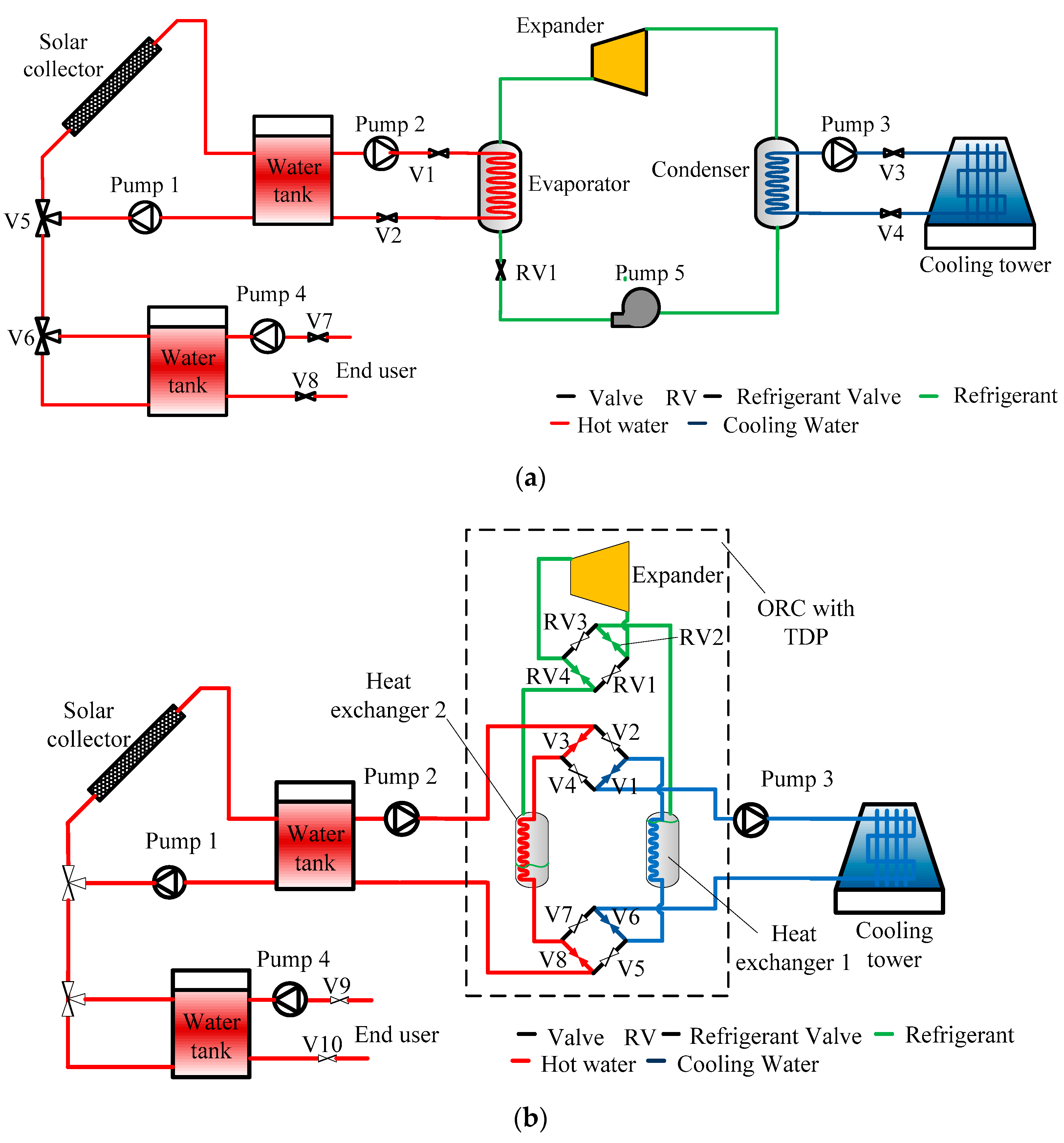
Figure 1 indicates the schematic diagrams of combined solar heat and power systems. The solar collector provides the thermal energy for evaporating the working fluid. One water tank between the ORC system and solar collector serves as a heat exchanger, which could be replaced by a thermal energy store vessel where phase change materials can be considered as the storage media. Another water tank could be used to supply the domestic hot water for end users from the heat rejected by the condensation [
14]. It will be a reduction in the fuel demand to heat the water. The electricity generation by ORC is set to be prioritised over water heating. A proportion of the solar collector fluid will be transferred to the domestic hot water tank only when the collector fluid is at a higher temperature than the hot water tank plus a pinch difference. When this temperature is higher than the critical temperature of working fluids, excess solar heat is rejected directly to the hot water tank. No heating is delivered to the hot water tank if its mean temperature is above the maximum hot water storage temperature [
5]. Since the ORC is the main investigation target, the storage part is not analysed in the rest of this paper.
As shown in
Figure 1a, the conventional ORC is mainly composed of two heat exchangers (evaporator and condenser), an expander and a working fluid pump. Its principle is the same as that of the Rankine cycle. Working fluid is pumped into a boiler, where it is evaporated and passes through an expander for power generation. Then, it goes through a condenser, where it is finally condensed. Due to energy consumption of the electrical driven pump, the basic ORC may enjoy a very low energy efficiency when the heating temperature is low and the rated power output is small. To solve this problem, the ORC part replaces the electrical driven pump with TDP, which is shown in the dashed area of
Figure 1b.
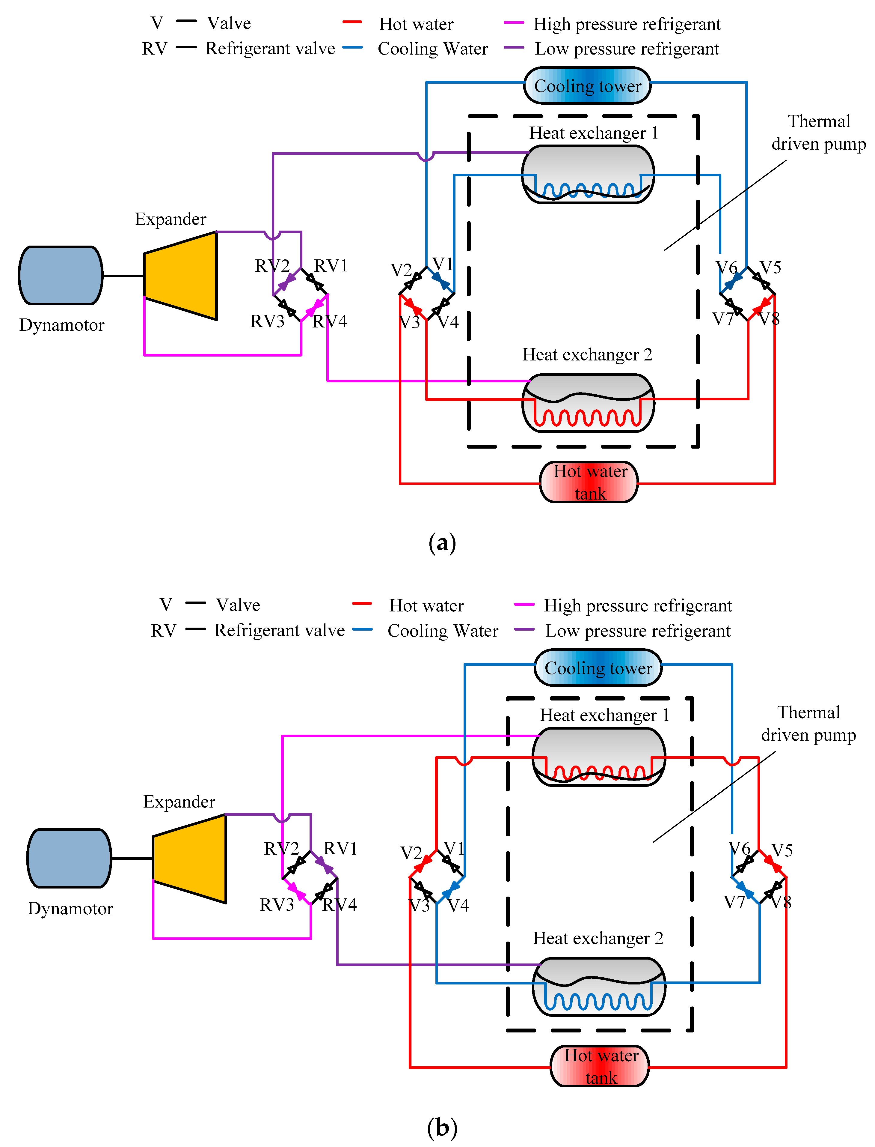
Figure 2 presents different operation modes of ORC using TDP. The ORC using TDP is mainly composed of two high-efficiency heat exchangers, i.e., heat exchanger 1 and heat exchanger 2, an expander, a generator and other auxiliary components [
49]. The working processes consist of a pre-expansion process and a power generation process, which are briefly illustrated as follows: (a) Pre-expansion process. Heat exchanger 1 acts as a condenser while heat exchanger 2 works as an evaporator. Water valves V1, V3, V6 and V8 are open, and all other valves are closed. The evaporator that is full of the working fluid, i.e., heat exchanger 2, undertakes isochoric heating through hot water, and its pressure increases gradually until it becomes constant. Meanwhile, the working fluid in the condenser, i.e., heat exchanger 1, starts as saturated vapour at a high temperature and pressure. The condenser applies an isochoric cooling process. (b) Power generation process. When the pressure of the evaporator becomes constant and the condenser achieves a cooler level, RV2 and RV4 are opened. Then, the working fluid with high temperature and pressure from the evaporator flows into the expander and generates the power. The power is outputted until there is no pressure difference between the evaporator and condenser. During this process, the high-pressure working fluid in the evaporator is isobarically heated. The exhaust enters the condenser and is condensed into saturated liquid. When the generator does not produce power, RV2, RV4, V1, V3, V6 and V8 are closed. This whole process that is termed as a generalised working cycle is shown in
Figure 2a. Then heat exchanger 1 and 2 swap their roles as condenser and expander. A new cycle starts as indicated in
Figure 2b, which is similar to previous pre-expansion and power generation processes. A working mode for the ORC using TDP could be according to
Table 1. For further clarification of the whole process, different operating modes of water and refrigerant valves for the ORC using TDP are listed in
Table 2. It is noted that heat exchangers 1 and 2 are always heated and cooled inversely. No power output is obtained in the pre-expansion process, which slightly reduces the average output.
In fact, the working fluid pump is replaced by the TDP, i.e., the switch of two heat exchangers as shown in the dashed area of
Figure 2. Compared with the conventional ORC, the ORC using TDP may have a higher energy efficiency since the pump is eliminated. Additionally, it is worth noting that continuous power output could be obtained in the power generation process, and thermal continuity is influenced by the pre-expansion process. To solve this problem of continuity, it tends to use two or more ORCs with TDPs for power generation alternatively. However, it is acceptable for the solar ORC, which can utilise battery technology for electricity storage.
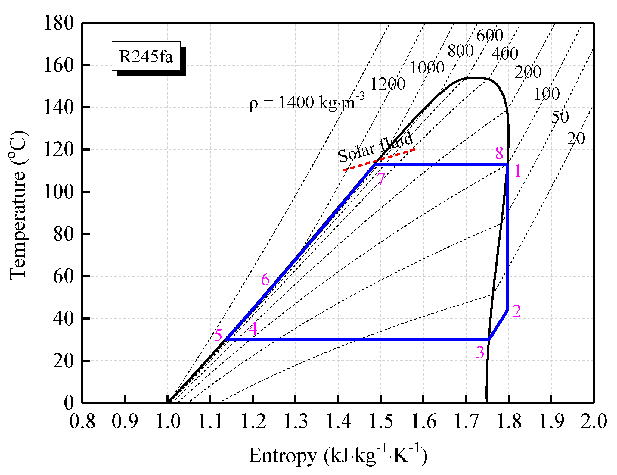
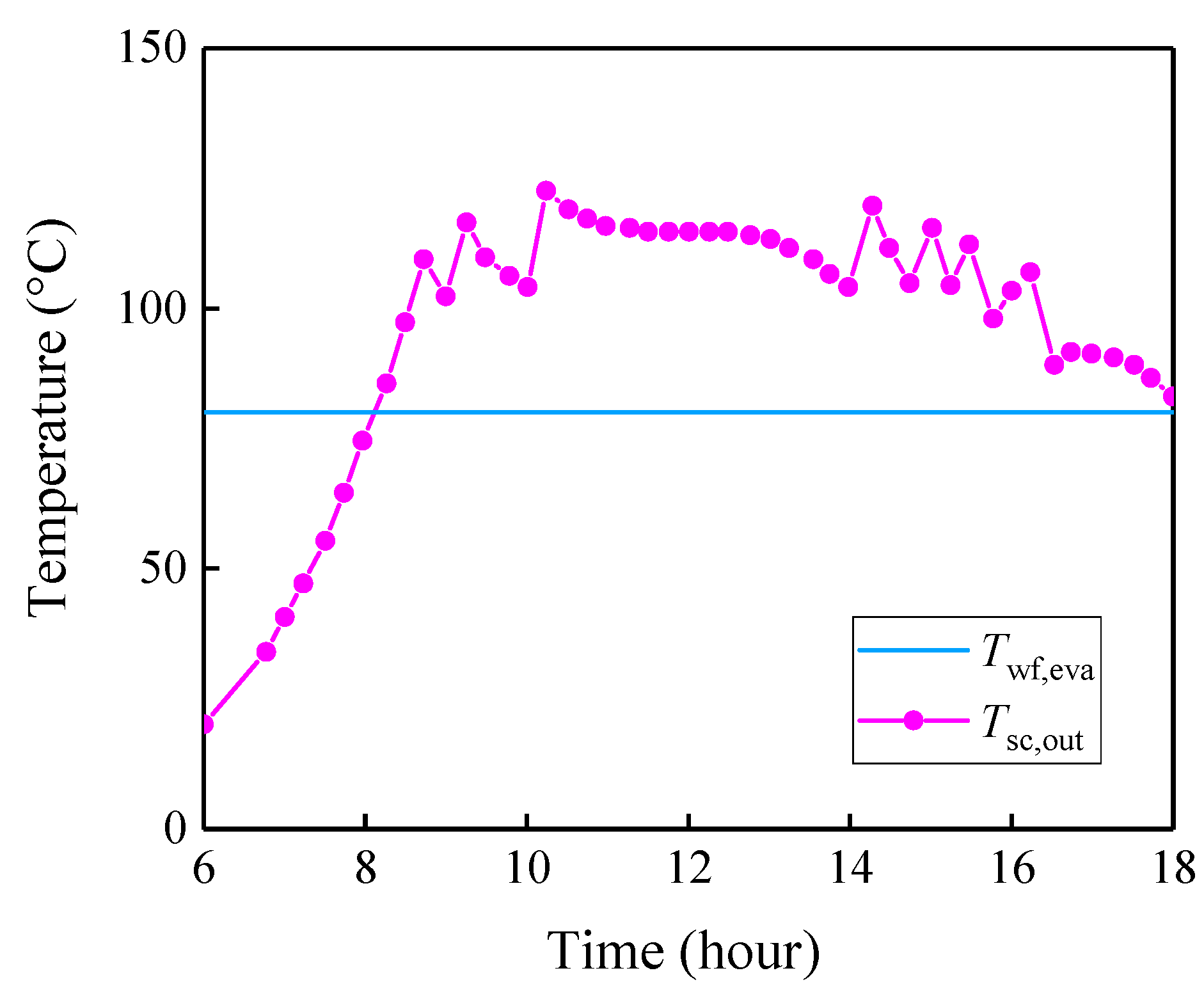
A
T-s diagram of a solar ORC cycle using a typical working fluid, i.e., R245fa, is shown in
Figure 3. The heat is obtained from a solar collector using water as a heat transfer fluid. A fixed superheated temperature difference Δ
Tsuperheated of 5 °C is assumed between the heat source fluid inlet and working fluid outlet. Thus, the working fluid outlet temperature is evaluated as
T1 =
Tsc,1 − Δ
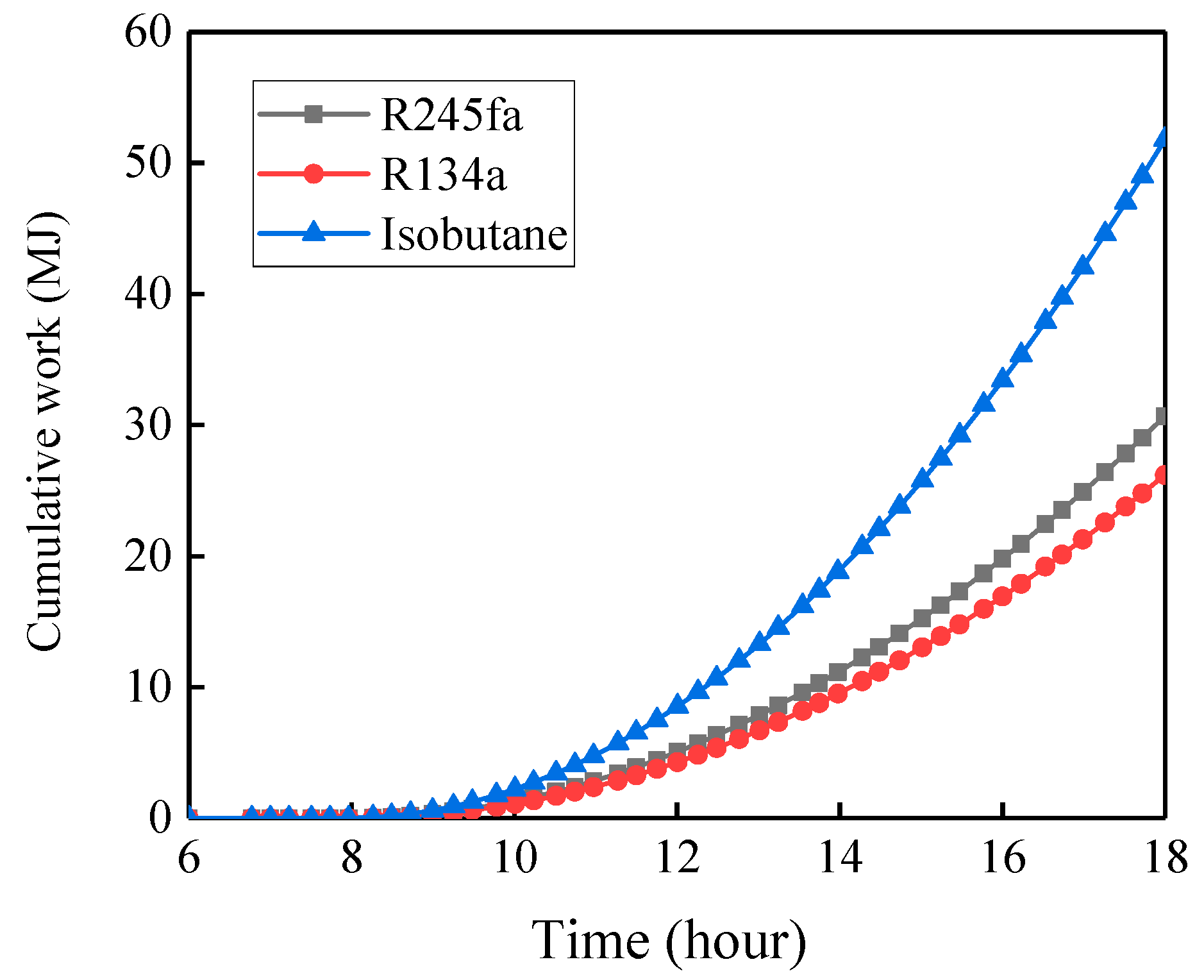
Tsuperheated. In order to comprehensively evaluate the performance, refrigerants of R245fa, R134a and isobutane are chosen as the working fluids for solar ORC systems. These refrigerants have been verified as well-suited candidates for low-temperature ORC applications due to their thermodynamic and physical properties, low flammability, corrosiveness and environmental impacts [
5,
20]. The thermodynamic data of these organic compounds are obtained from REFPROP 9 (National Institute of Standards and Technology, Gaithersburg, MD, USA).


