2.3.1. Kiln without Thermal Insulation
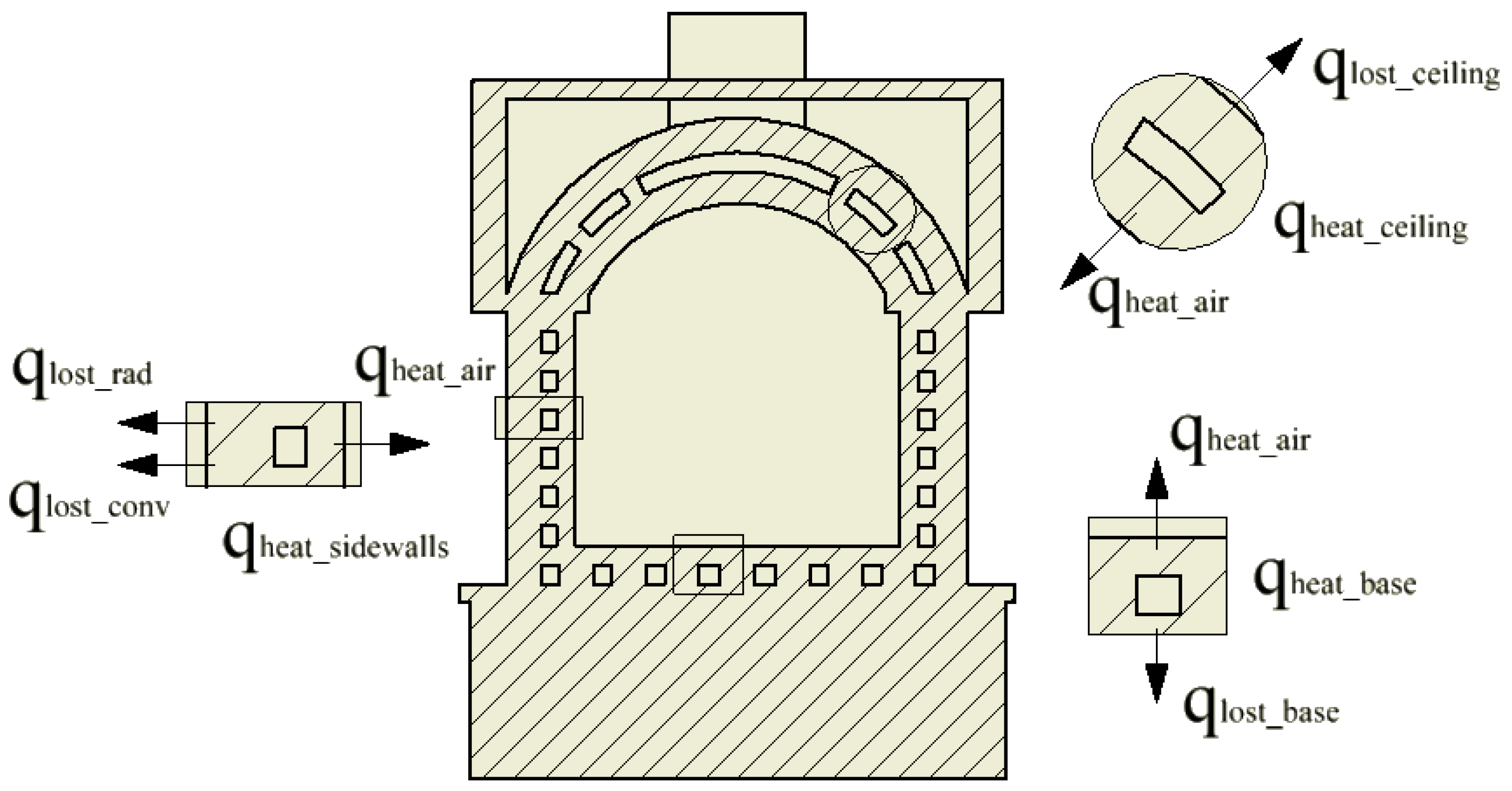
For this analysis, consider
Figure 3, which illustrates the different heat transfer portions involved in the process. The figure shows a section of the kiln/dryer analyzed, where it is possible to verify the channels through which the combustion gases flows, as well as small control volumes in the sidewalls, base, and ceiling of the kiln, which indicate the directions of the heat fluxes.
From the first law of thermodynamics (energy conservation law), we obtain the energy balance in the kiln, which is represented by Equation (1), in the form of the temporal rate:
where the terms on the left side of the equation represent, respectively, the energy rate that enters the control volume, the energy rate that leaves the control volume, and the energy rate that is generated.
is the rate of energy stored in the system.
For the case of the non-insulated kiln, the energy balance can be represented by Equation (2), as follows:
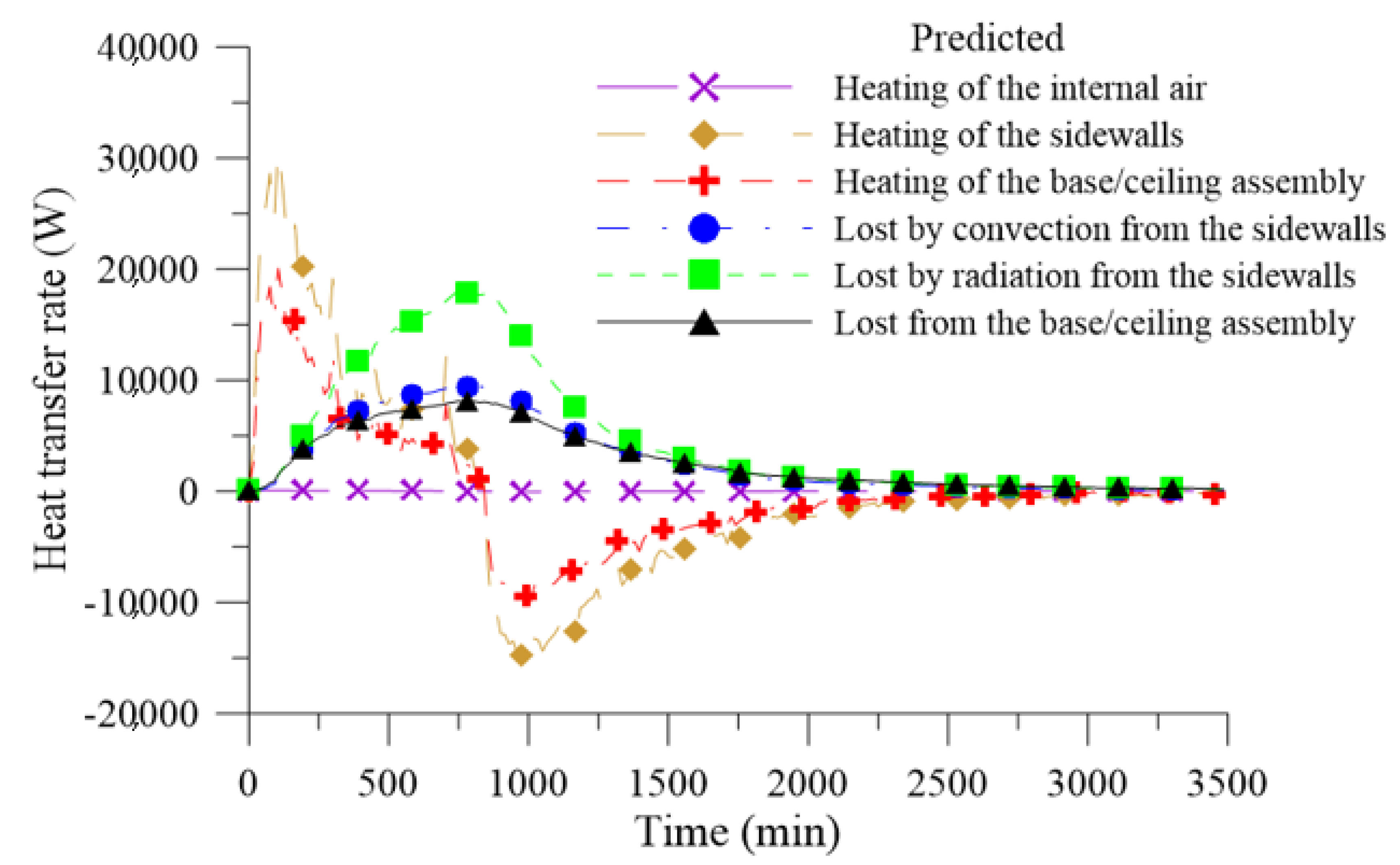
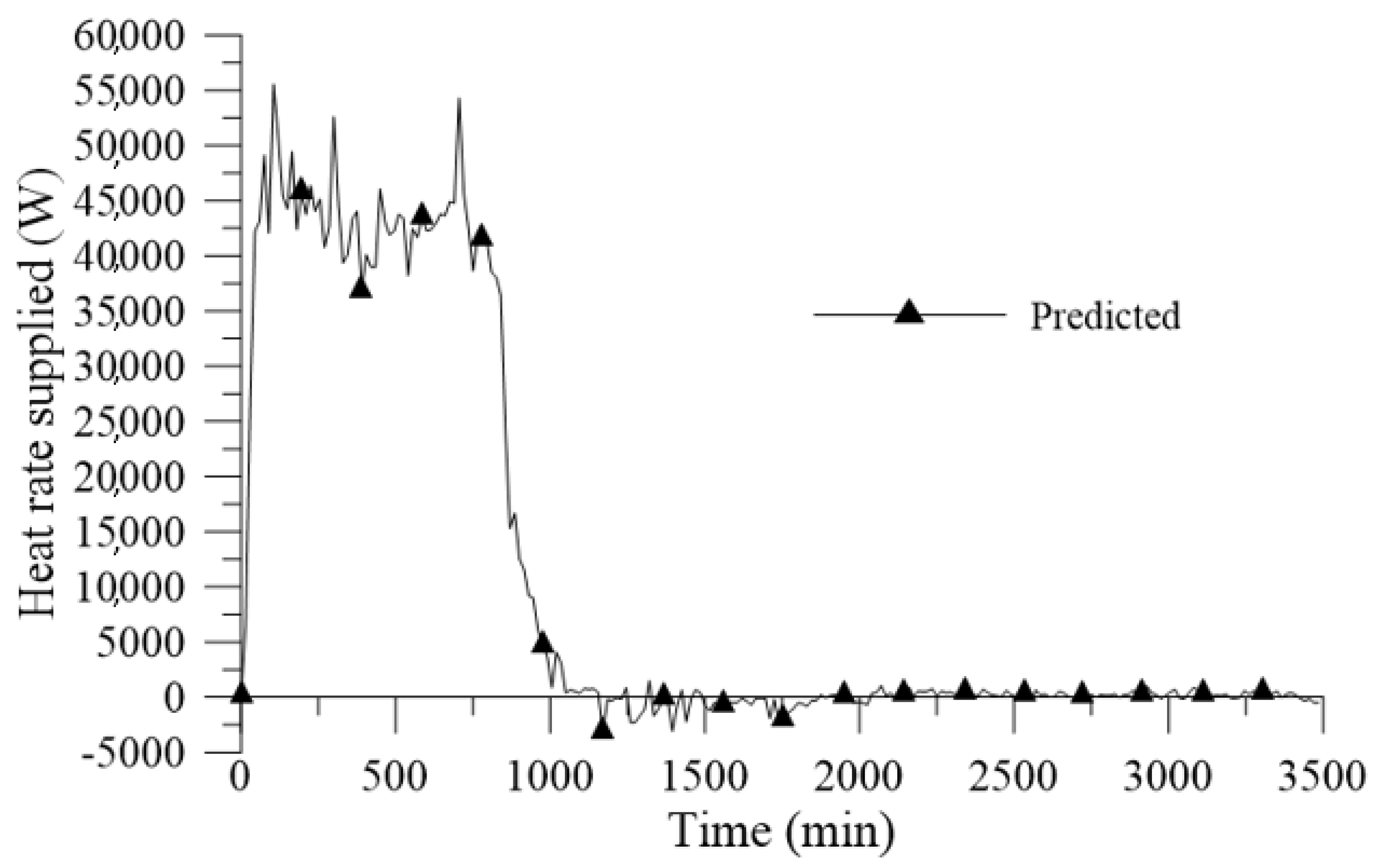
Thus, the rate at which the energy is supplied, , from the combustion of natural gas is given by the sum of the rate at which energy is stored in the kiln () with the heat lost ().
The rate of energy stored in the kiln is obtained by summing the portions of the energy to heat the ceramic products, the internal air, the sidewalls, and the base/ceiling assembly of the kiln, as indicated in Equation (3):
Since the experiment was performed without products inside the kiln, it is assumed that the portion, .
The heat loss (
) is given by the sum of the heat transfer rates lost by the four side faces of the kiln and the heat transfer rate lost by the base/ceiling assembly of the kiln, according to Equation (4):
The rate for heating the internal air at each instant of time is obtained by Equation (5), as follows:
where
is the mass of air inside the kiln,
is the specific heat at constant pressure of the air, and
is the variation of the internal temperature of the kiln in a given time interval, Δt.
To obtain the specific heat of the air,
, for each instant of time, interpolations were performed with values provided by Bergman [
45] for atmospheric air.
Considering air as an ideal gas, the mass of air,
, can be calculated by the Clapeyron equation (Equation (6)):
where P is the pressure, V is the volume inside the kiln, R is the universal gas constant (R = 8.31 J/mol/K), T is the temperature in Kelvin, and M is the molar mass of the gas.
Considering that the kiln was closed during the whole experiment, it is assumed that the mass of air contained within the kiln does not change with time. In this way, the mass of air can be calculated at the instant of time, t = t0 = 0 s, where the ambient temperature and the atmospheric pressure are known.
The rates for heating the sidewalls and the base/ceiling assembly of the kiln are represented by Equations (7) and (8), respectively, as follows:
where the masses,
and
, are calculated by the product of the density of the refractory brick with its respective volume. The values used for the density and specific heat of the refractory brick were 2500 kg/m
3 and 840 J/kg·K.
The data collection of the temperatures in the kiln was done at intervals of 15 min (Δt = 900 s.). The variation of the average temperature in the kiln is given by Equation (9):
The average temperatures at time instants t and t + Δt are obtained by Equations (10) and (11), respectively:
where
and
are the internal and external surface temperatures of the kiln sidewalls, respectively.
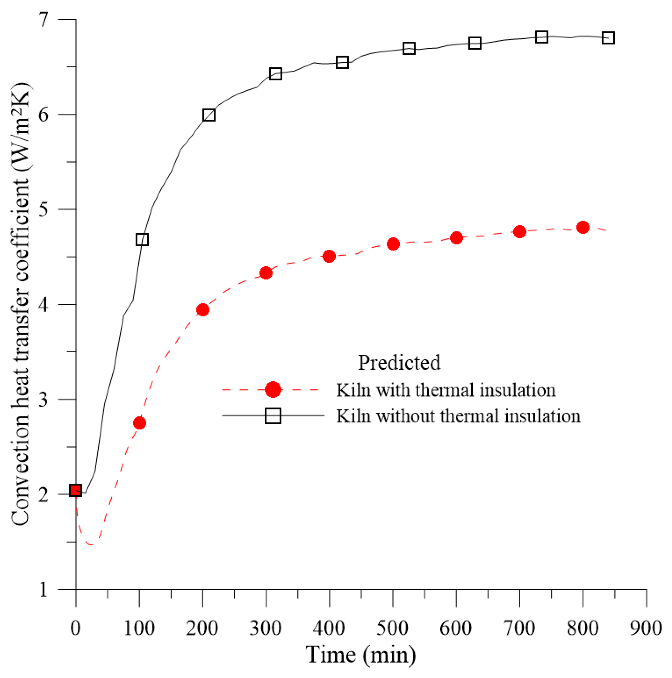
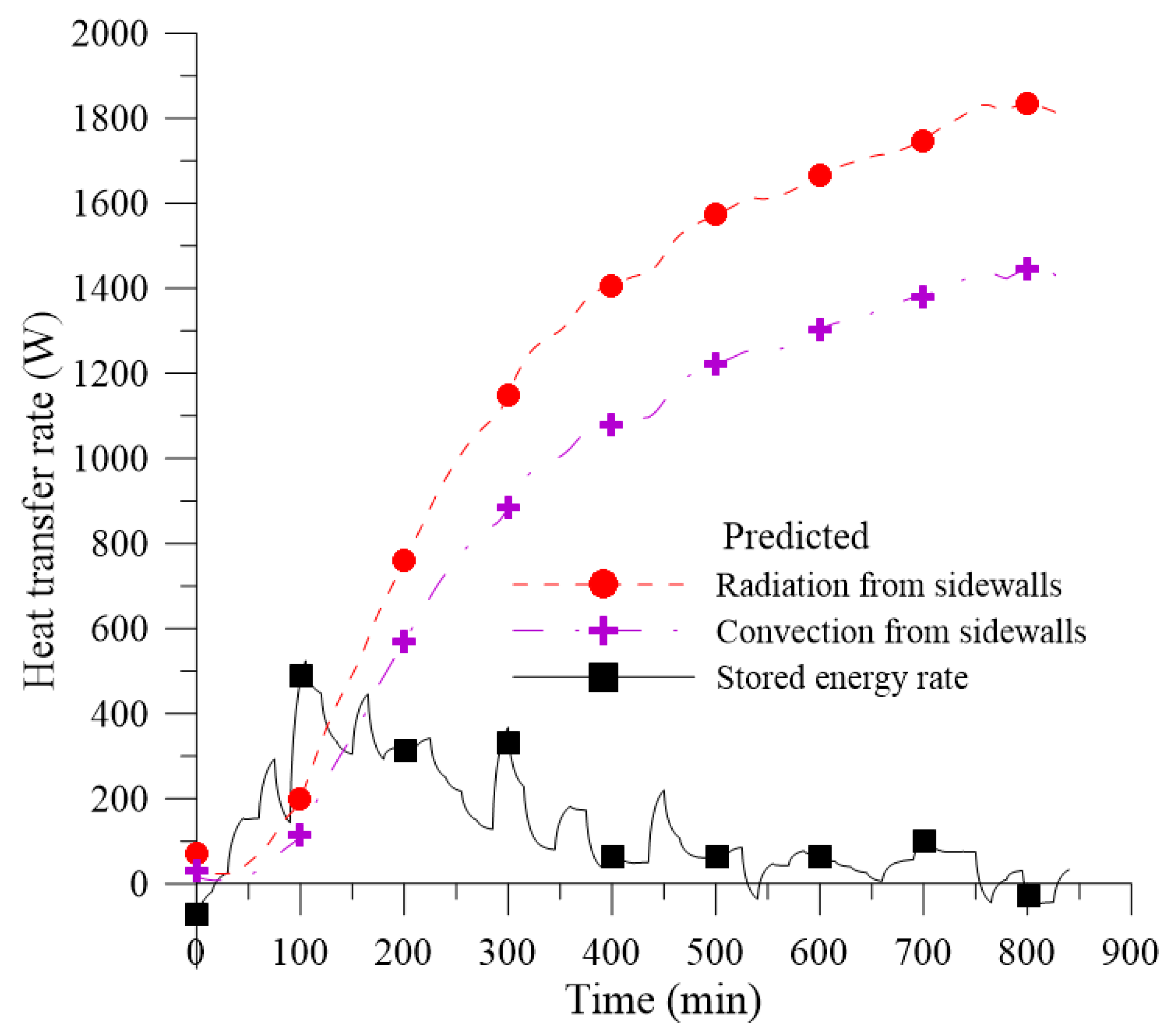
The energy lost by the sidewalls of the kiln was divided into two portions: Heat lost by convection,
, and heat lost by radiation,
, according to Equation (12):
The heat lost by convection is given by Equation 13:
where A = 6.48 m
2 is the sum of the outer sidewall areas of the kiln,
is the convective heat transfer coefficient,
is the external surface temperature, and
is the temperature of the fluid that is in contact with the outer surface of the kiln (ambient air).
The convective heat transfer coefficient is a proportionality constant that summarizes the conditions in the boundary layers closest to the surface, and is dependent on the thermophysical properties of the fluid (density, viscosity, thermal conductivity, and specific heat), surface geometry, and nature of the flow (forced or natural convection, laminar or turbulent regime). This parameter can be obtained by the average Nusselt number (Equation (14)), as follows:
where
is the characteristic length, which, for the present case, corresponds to the outer sidewall height of the kiln, and
is the thermal conductivity of the fluid (ambient air).
As there is no presence of external sources to promote the movement of the fluid that is in contact with the kiln, it is assumed that the nature of the flow is by natural (or free) convection. In this way, the flow is induced by buoyancy forces, which originate from density differences caused by temperature variations in the fluid [
45].
Modeling the sidewalls of the kiln as vertical flat plates and considering the laminar flow (10
4 ≤ Ra
L ≤ 10
9), the correlation recommended by Churchill and Chu [
46] was used to calculate the average Nusselt number (Equation (15)), as follows:
where
is the number of Prandtl, which represents the ratio between the momentum and thermal diffusivity of a fluid, and
is the Rayleigh number, defined by Equation (16):
where g is the gravity acceleration,
is the volumetric expansion coefficient,
and
are the outer surface temperature of the kiln and ambient temperature, respectively.
is the characteristic length,
is the kinematic viscosity, and
is the thermal diffusivity.
The values of the parameters, Pr, β, ν, and α, were tabulated according to the type and temperature of the fluid. For each instant of time, such values were obtained by interpolations taking into account the film temperature (
), which correspond to the average temperature between the ambient temperature and the temperature of the outer surface of the kiln (Equation (17)), as follows:
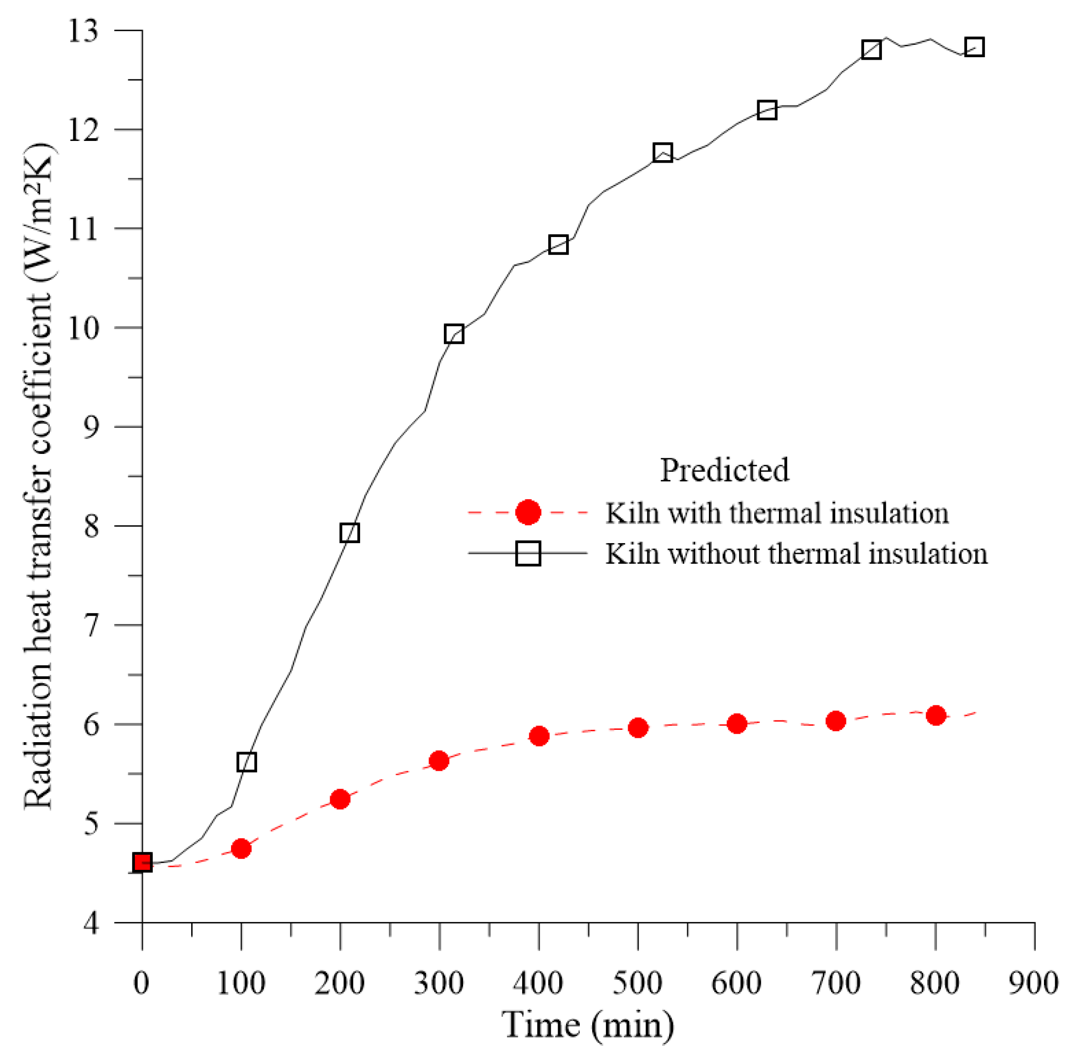
The heat lost by radiation is given by Equation (18), as follows:
where A is the sum of the areas of the outer sidewalls of the kiln, ε is the emissivity of the refractory brick surface (ε = 0.75 [
47]), σ is the Stefan-Boltzmann constant (σ = 5.67 × 10
−8 W/(m
2.K
4)), and T
s,ext and
are the absolute temperatures of the outer surface of the kiln and the surroundings, respectively.
Heat lost by radiation is usually expressed similarly to heat lost by convection, as shown in Equation (19):
where, from Equation (18), the radiation heat transfer coefficient,
, is given by Equation (20):
To determine the energy lost by the base/ceiling assembly, the system was modeled as a semi-infinite solid, which provides a useful idealization for the transient response of a finite solid, such as a thick slab [
45]. For such modeling, temperatures at distant points, both below the base and above the dome (curved portion) of the kiln, are considered to be essentially unaffected by the change in surface conditions. Using the case of a constant surface temperature, which is more appropriate for the analysis presented here, the heat transfer rate lost by the base/ceiling assembly is given by Equation (21), as follows:
where
is the thermal conductivity of the material,
is the base/ceiling assembly area,
is the thermal diffusivity of the material, and
represents the average temperature of the base and the ceiling of the kiln, which is calculated by Equation (10).
For the present case, the thermal properties of the sand were used, which was the predominant material used in the construction of the kiln base and in the region between the dome and the ceiling of the kiln. The sand was used to reduce heat losses to the environment.
Equations (1) to (21) were solved for each of the 234 time steps of the heating and cooling processes of the kiln without insulation using the Microsoft Excel software. As a result, all the heat transfer rates that occurred throughout all the heating and cooling steps of the kiln were identified. In addition, the total energy and the rate at which energy was supplied by the combustion gases as a function of the processing time were calculated.
2.3.2. Kiln with Thermal Insulation
In addition to performing the thermal analysis of the kiln as it was constructed (without thermal insulation), this work aims to verify the influence of the use of thermal insulation for the sidewalls of the equipment by quantifying the new heat losses and temperature distributions in the thermal insulation as well as the global energy gain that it provides for the system.
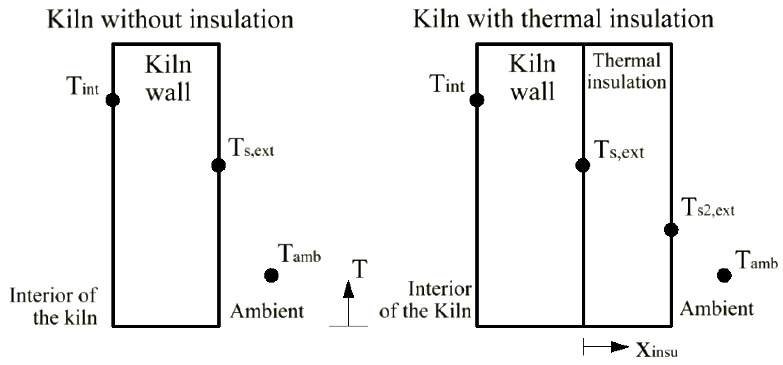
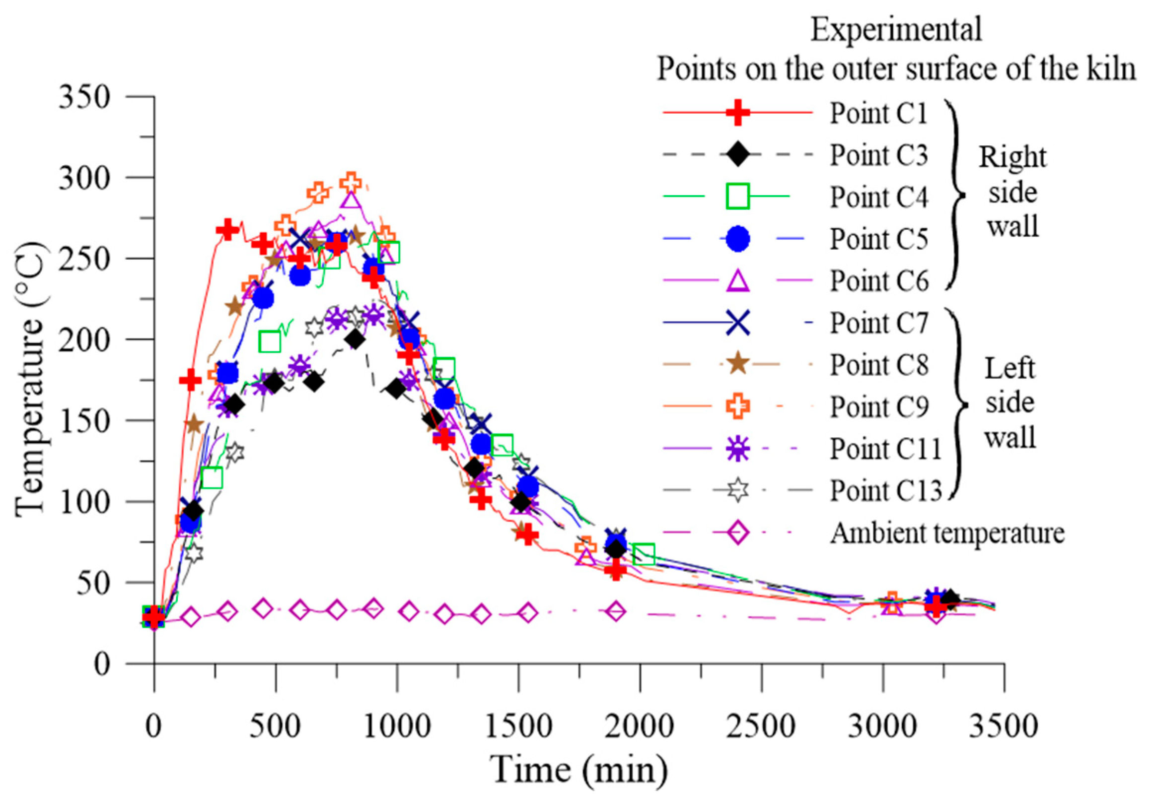
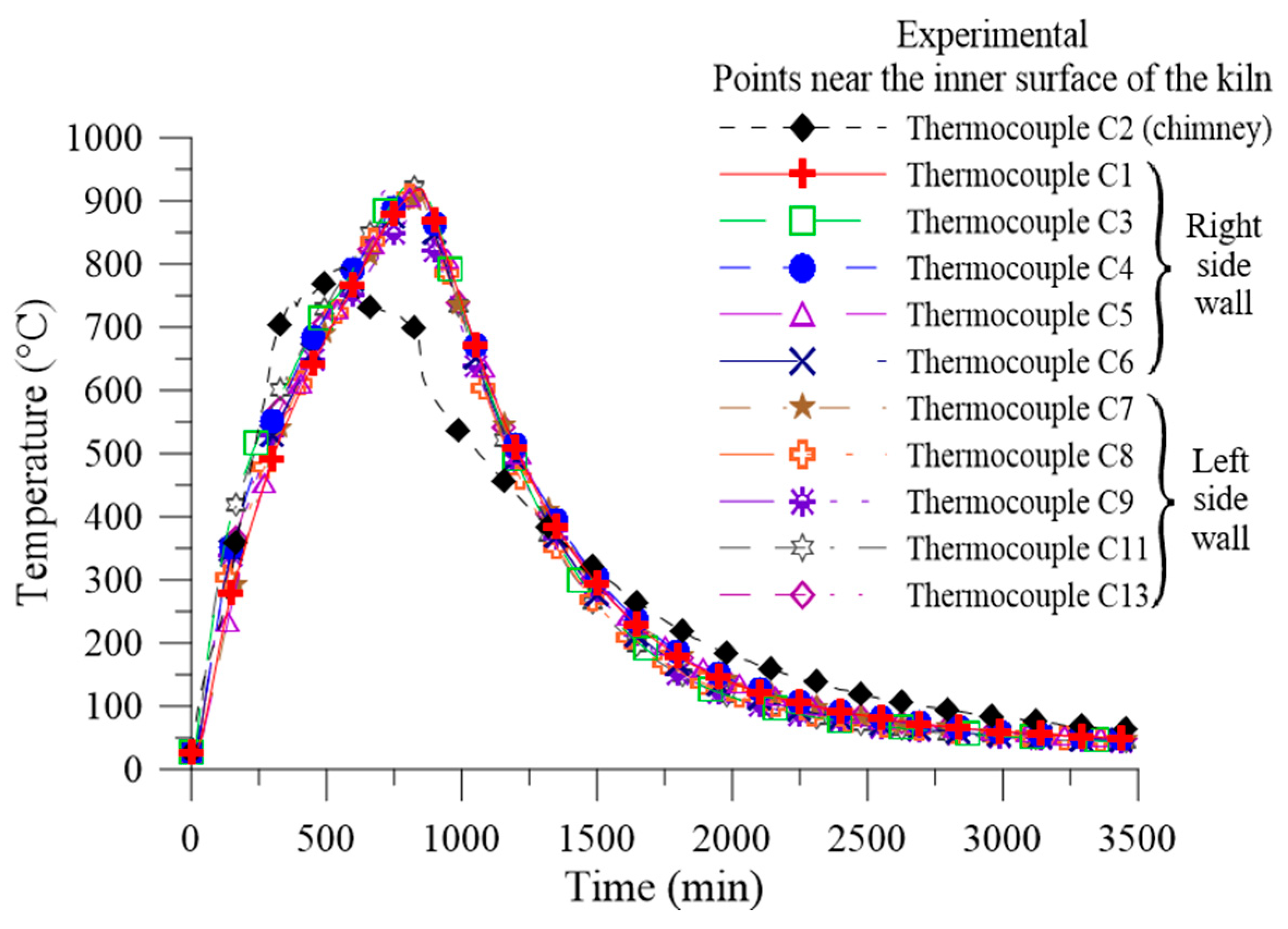
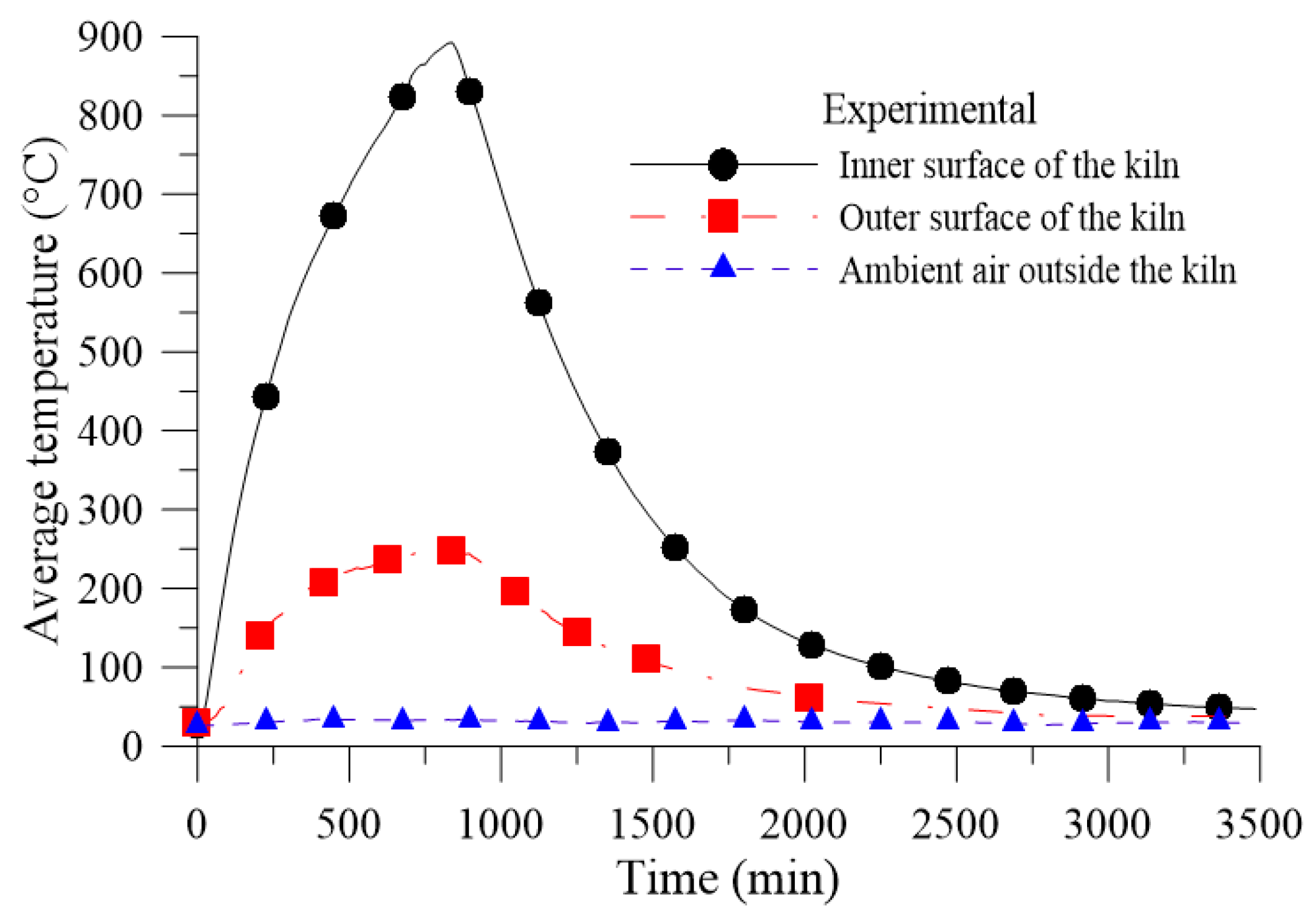
In order to conduct such an analysis, the internal (T
int) and external (T
s,ext) temperatures of the sidewalls of the kiln with thermal insulation during heating were considered to be the same as those obtained for the experiment with the kiln without thermal insulation, as indicated in
Figure 4. This ensures that the firing curve was the same for both analyzed cases.
With this new configuration, the external temperature of the insulation, Ts2,ext, is unknown, thus not allowing the determination of the amount of heat lost by convection and radiation to the surroundings. Therefore, it must be determined.
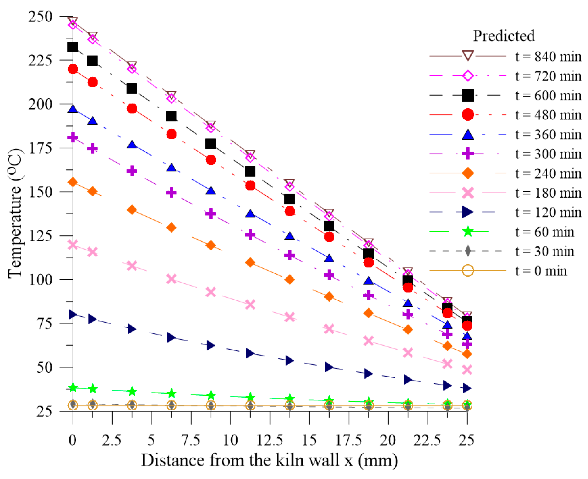
The type of thermal insulation analyzed was the Ceramic Fiber–LD–1200 with a thickness of 25 mm.
Table 1 shows the thermal conductivity of the insulation as a function of the temperature, as well as the density, specific heat, emissivity, and recommended temperature range.
For this, it was assumed that the heat transferred inside the thermal insulation is given by pure conduction. In this case, the general differential equation for one-dimensional and transient heat conduction is governed by Equation (22), as follows:
where ρ, c
p, k, T, and S are the density, specific heat, thermal conductivity, temperature, and the source term, respectively, of the thermal insulation. For cases of heat transfer, the term source represents the rate at which energy is generated per unit volume [
48].
The following initial and boundary conditions were used to model the heat transfer in thermal insulation:
- (a)
- (b)
Boundary condition on the wall of the kiln (x = 0):
- (c)
Boundary condition on the outer surface of the insulation (x = L):
where T
amb = T
∞ = T
sur.
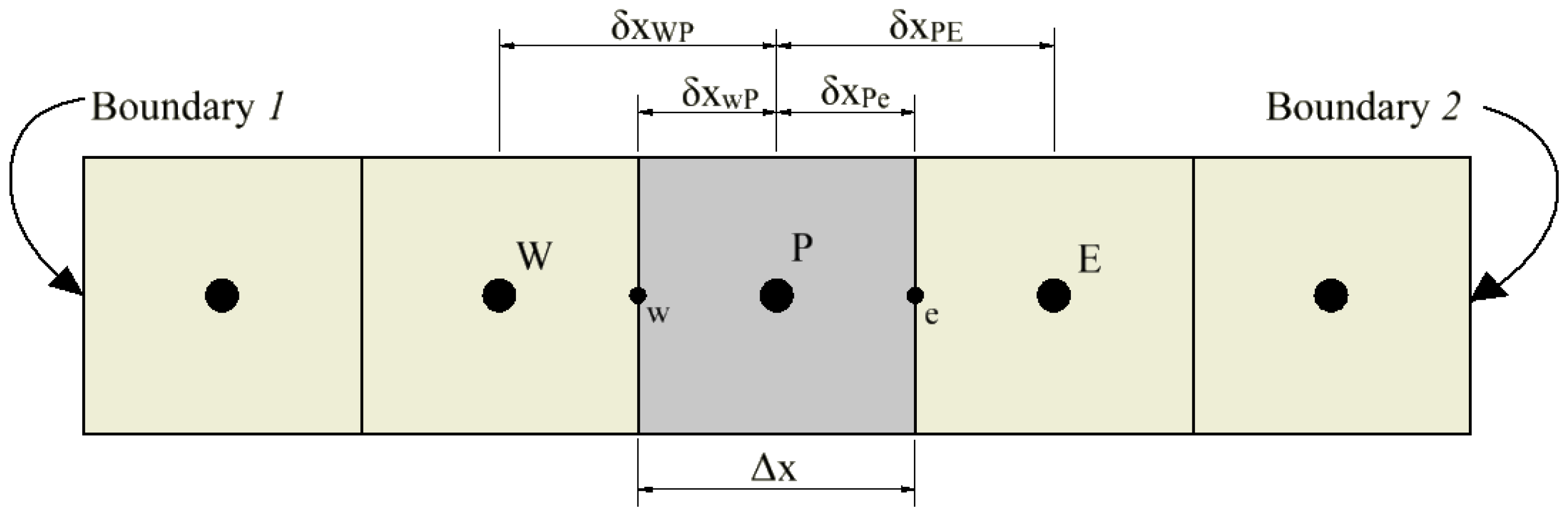
The numerical method used to solve Equation (22) was based on finite volume formulation. This method consists of dividing the domain into discrete sub-domains or control volumes and integrating the differential equation (Equation (22)) under each of these sub-domains and over time in order to obtain a set of algebraic equations relating the control volumes of the domain. For this, the domain of the thermal insulation was considered as being divided into five control volumes, as shown in
Figure 5. The centroid of the control volume analyzed, in this case the third one, is always identified by the letter, P. The centroids of the west and east control volumes of this are identified by W and E, respectively. Similarly, the west and east faces of the analyzed control volume are identified by w and e. The distance between the west and east faces are identified by Δx, and represents the length of the control volume, P. The distances between the centroids, W and P, and between P and E are identified by
and
, respectively. Similarly, the distances between the face, w, and the centroid, P, and between P and the face, e, are identified by
and
, respectively.
The discretization was done in such a way that the west face of the first control volume and the east face of the last control volume are coincident with the domain boundaries, x = 0 and x = L, respectively, ensuring that all control volumes are whole and of the same size (Δx).
Integrating Equation (22) on a given central control volume and over a time interval from t to Δt, the following equation can be formed:
As this is a transient problem, in this research, the fully implicit discretization scheme was used [
48,
49,
50]. Disregarding the term source, and solving the integrals of Equation (26), we have the discretized equation for the control volumes of the computational domain, as follows:
where:
The values of the coefficients,
, and
, for each control volume are shown in
Table 2.
The variables, k
w, k
e, k
f1, and k
f2, are, respectively, the thermal conductivities in the faces west, east, west of the first control volume, and east of the last control volume. For simplification, these values of thermal conductivity were considered as constants for all control volumes at a given time, but changing from one instant to another as a function of the average temperature of the thermal insulation, according to Equation (29):
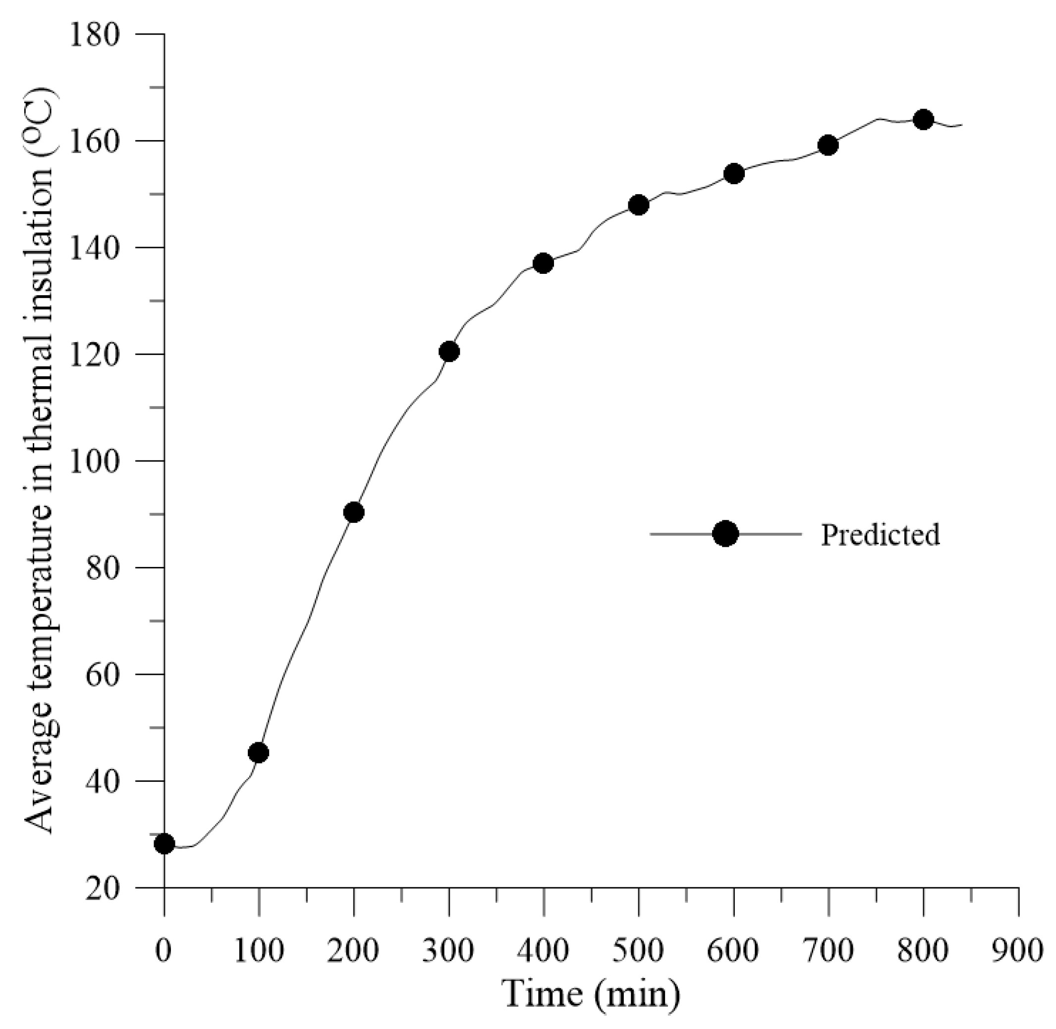
where
is the average temperature of the thermal insulation at time t, N is the number of control volumes, and
is the temperature at the control volume, I, at time t. It is important to state that Equation (27) was applied to each control volume. This generated a system of linear algebraic equations that must be solved at each instant of time. For this, the iterative calculation available in Microsoft Excel software was enabled.
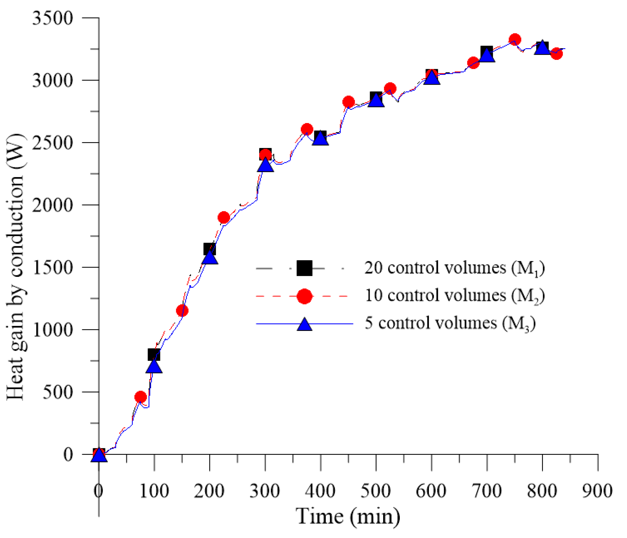
To ensure that the results obtained were independent of the number of control volumes, a mesh convergence and time step refinement study were performed.
The mesh convergence analysis for the thermally insulated kiln was performed using the methodology proposed by Celik [
51], based on Richardson's extrapolation [
52,
53]. Celik [
51] provides specific guidelines for the estimation of discretization errors in computational fluid dynamics simulations for situations with or without experimental data for comparison. Using this methodology, it is possible to estimate the exact solution from the extrapolation of the solutions of the existing meshes, as well as to determine the ideal mesh through the calculation of the grid convergence index (GCI). The entire procedure for such an analysis will be described in the following.
Initially, one should determine a representative mesh size, l, according to Equation (30):
where N is the number of mesh elements used for the computational calculation and ΔV is the volume occupied by element i.
For the case of one-dimensional meshes, we have:
where N is the number of mesh elements used for the computational calculation and Δx is the length of the control volume, i.
Celik [
51] recommends making three meshes with a refinement factor, r = l
course/l
fine, greater than 1.3. l
1 and l
3 are the representative sizes of the most refined and coarser meshes, respectively. With these parameters, r
21 and r
32 parameters are defined by Equations (32) and (33):
Also, let ϕ1, ϕ2, and ϕ3 be the results of a given response variable for the respective meshes.
With this, it is possible to calculate the apparent order, p, required for the calculation of the extrapolated solution (l = 0) and grid convergence index (GCI), using Equations (34)–(36), as follows:
where ε
32 = ϕ
3 − ϕ
2, ε
21 = ϕ
2 − ϕ
1. If
, then
. Similarly, if
, then
. Equations (37) to (39) can be solved using an iterative method. It is observed that q(p) = 0 for r
21 = r
32.
To verify the apparent convergence condition of the solution, we used Equation (37), as follows:
Based on the value of C, the convergence condition can be classified according to
Table 3 [
54]. According to Almohammadi [
54], for the Richardson extrapolation method to be valid, it is necessary to obtain a monotonic convergence condition for the analyzed variable.
The extrapolated solution was determined according to Equation (38), as follows:
The approximate relative error between the meshes, for the variable,
, was also determined according to Equations (39) and (40):
In this way, the grid convergence index (GCI) was calculated using Equations (41) and (42), as follows:
To apply this method, it is necessary to ensure that the meshes are within the asymptotic range. Roache [
55] reports that in cases where the exact solution is not known, the formula given by Equation (43) can be used to indicate that the asymptotic interval has been reached:
For this analysis, the conduction energy gain by the thermal insulation, or energy entering the thermal insulation, in the heating phase of the kiln (
), was considered as a response variable (ϕ) and calculated using the numerical integration known as the composite trapezoid rule, according to Equation (44):
where:
where a is the initial time instant (a = 0 s), b is the time instant when the kiln is turned off (b = 840 min), and n represents the number of time steps in the heating step.
e
are the rates of energy entering the thermal insulation by conduction at the time instants, a, b, and i, respectively.
In order to ensure that the results obtained by the finite volume method are reliable, it is useful to calculate the global energy balance in the thermal insulation (Equation (46)). This ensures that the rate of energy entering the thermal insulation (
) is equal to the rate of energy leaving the thermal insulation (
) plus the rate of energy stored in the insulation (
) at each time step.
Replacing the terms for each variable, we have Equation (47), as follows:
where k
iso, ρ
iso,
, and L
iso, are the thermal conductivity, density, specific heat, and thickness of the thermal insulation, respectively, according to
Table 1.
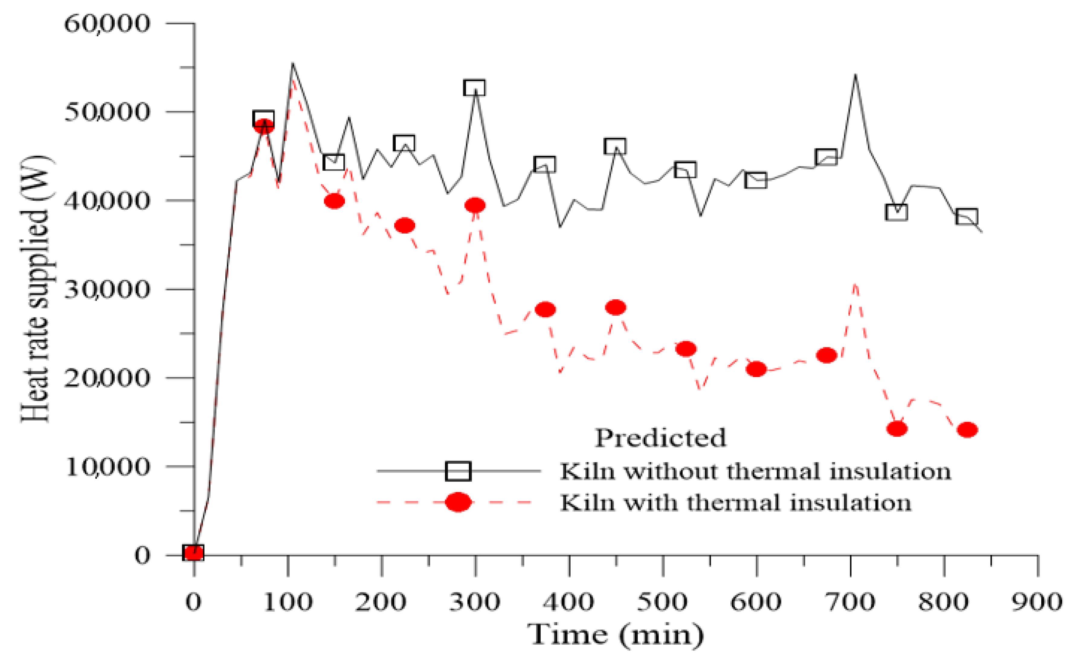
In order to quantify the influence of the thermal insulation on the kiln efficiency, the global energy gain variable is used, which can be calculated by Equation (48), as follows:
where
and
are the energies supplied during the heating process for the kiln without and with thermal insulation, respectively. The parameter,
, is given by:
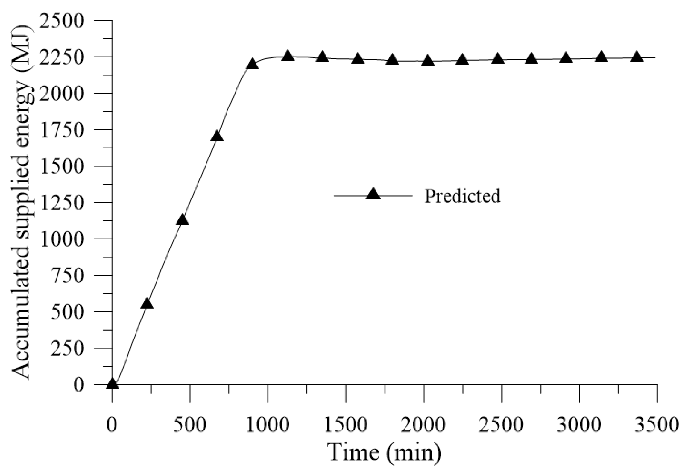
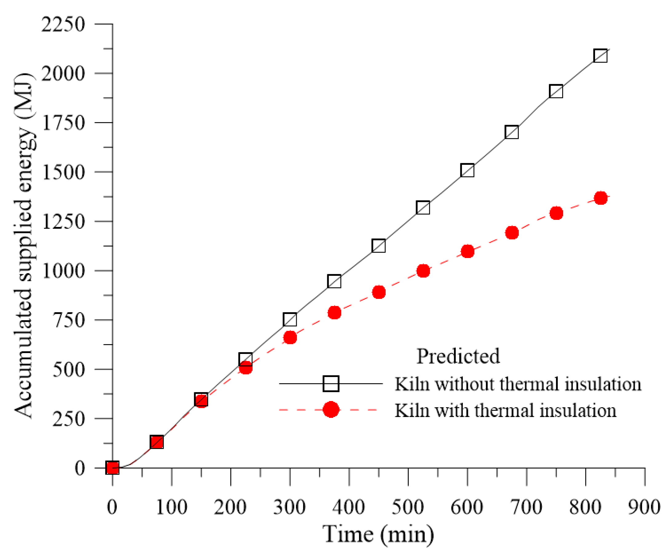
In order to determine such values, it is necessary to calculate the definite integral of the variables of (Equation (2)) and (Equation (49)) during the heating time interval of the kiln.
Using the composite trapezoid rule mentioned before, the accumulated energy supplied,
, during the heating process can be determined according to Equation (50), as follows:
where a is the initial time instant (a = 0 s), b is the last time instant of the heating step, and n represents the number of time steps in the heating step.
e
are the heat rates supplied at the time instants, a, b, and i, respectively.
can be calculated in a similar way from Equation (50).


