Article

Local Buckling Characteristics of Stainless-Steel Polypropylene Deep-Sea Sandwich Pipe under Axial Tension and External Pressure

1
State Key Laboratory of Hydraulic Engineering Simulation and Safety, Tianjin University, Tianjin 300072, China
2
Tianjin Key Laboratory of Port and Ocean Engineering, Tianjin University, Tianjin 300072, China
3
College of Mechanical and Marine Engineering, Beibu Gulf University, Qinzhou 535011, China
*
Author to whom correspondence should be addressed.
Energies 2021, 14(16), 4866; https://doi.org/10.3390/en14164866
Submission received: 7 July 2021 / Revised: 21 July 2021 / Accepted: 6 August 2021 / Published: 9 August 2021
(This article belongs to the Special Issue Renewable Energy Systems for Buildings)

Abstract

:
In this paper, the effects of different loading paths of axial tension and external pressure on the collapse pressure of sandwich tubes are studied by experiments and finite element models. The difference of the two loading paths is investigated. Eight experiments were carried out to study the influence of different loading paths on pipeline collapse pressure under the same geometric and material parameters. Parameterization studies have been carried out, and the results are in good agreement with the experimental results. The test and finite element results show that the loading path of external pressure first and then the axial tension (P→T) is more dangerous; the collapse pressure of the sandwich pipe is smaller than the other. Through parametric analysis, the influence of the axial tension and the diameter-to-thickness ratio of the inner and outer pipe on the collapse pressure under different loading paths are studied.

1. Introduction

With the shortage of onshore oil and gas resources, marine engineering has gradually received attention [1]. Risers and pipelines are widely used in the development of marine resources because of their stability, safety, and efficiency. During installation and operation, the riser and pipeline are subjected to loads such as internal pressure, external pressure, waves, and internal waves. Risers mainly bear the combined action of external water pressure and axial tension, while pipelines are subject to external pressure, axial tension, bending moment, transverse loading, and torque [2,3,4,5,6,7,8]. The motion of the offshore platform will drive the cyclic movement of the pipeline, which leads to the riser bearing the cyclic load, and the loading sequence of external water pressure and axial tension is constantly changing [9,10,11,12]. The sandwich pipe has good thermal insulation performance and structural strength, can resist high external water pressure, and is gradually being valued and applied in deep-sea engineering [13,14,15,16]. The ultimate bearing capacity of the sandwich pipe will be reduced under the action of tension loads, which will cause local instability of the pipe. Due to the limitation of the experiment equipment, most of the tests apply the tension load first, and then apply the external water pressure to study the ultimate bearing capacity of the pipeline. However, the loading sequence of external water pressure and axial tension has a great impact on the ultimate bearing capacity of the sandwich pipe. It is necessary to study the influence of different loading paths on the bearing capacity of the sandwich pipe.
As a substitute for the traditional single-layer tube, the sandwich pipe has received wide attention in the practical application of scientific research projects and scientific research, not only because of its good heat insulation and weight ratio but also because of its good resistance to external pressure. In the past few decades, researchers have analyzed different core materials through experiments. Estefen et al. [17] studied the influence of the lateral restraint of the steel pipe on the ultimate strength of the sandwich pipe through the scale ratio test. For the sandwich pipe with concrete as the core layer, researchers have performed a significant amount of research through experiments and found that uniaxial tension and compression and four-point bending have a great influence on the ultimate strength of the sandwich pipe. Castello et al. [18] carried out a numerical simulation of the sandwich pipe by the general commercial software ABAQUS and found that the interlayer bonding behavior has a great influence on the ultimate strength of the sandwich pipe when the sandwich pipe is subjected to a large bending moment and axial tension during the pipe laying process. Xu et al. [19] evaluated the stick-slip properties of epoxy resin and 3M-DP8005 adhesive under two surface conditions of steel pipes through axial tensile and four-point bending tests. Although there are studies on the performance of sandwich pipes, they are limited to local analysis. There are few studies on the overall collapse of sandwich pipes under axial force.
Researchers have conducted a large number of experiments to study the buckling propagation behavior of the sandwich pipe under external pressure. Pasqualino et al. [20], Lourenco et al. [21], Fu et al. [22], Gong et al. [23], and Gong et al. [24] studied the effect of interlayer bonding on the buckling propagation pressure of sandwich pipes through small-scale experiments and numerical simulations and established empirical expressions through numerical simulations. Gong et al. [25] studied the buckling propagation of sandwich tubes with integral buck arrestors under external pressure under different interfacial bonding conditions through high-pressure tank tests and found that interlayer bonding not only affects the collapse pressure but also has a great influence on the buckling propagation. To further study the influence of different parameters on the sandwich pipe, the researchers also conducted a significant amount of research on the sandwich pipe system through numerical simulation. Arjomandi et al. [26,27,28] studied the influence of the structural parameters of SP systems with different internal adhesion properties on their characteristics and pressure resistance, and the accuracy was verified by comparison with other studies, simplified practical equations were established, and the influence of the adhesive structure in the layer on the mechanical properties of the composite material was discussed. Xue et al. [5] proposed the first-order shear deformation theory of cylindrical sandwich pipes under the action of seabed water pressure, studied the circumferential radius change caused by the radial deflection of the sandwich cylindrical shell and its influence on the bending moment, and carried out numerical analysis of the sandwich cylindrical pipe with different slenderness ratios, diameter thickness ratios, and core plate thickness ratios through the development of a MATLAB program. He et al. [29] and Xu et al. [19] developed a special finite element model and discussed the effects of interlayer adhesion, thickness diameter ratio, core thickness, material parameters, relative initial ellipticity direction, and inelastic anisotropy on the failure pressure of SPs. Wang et al. [30] used the heat transfer differential equation for calculations, established a finite element model based on the fiber shell element, and studied the lateral buckling response of the sandwich pipe. Garg et al. [31] compiled and summarized a large number of numerical results in published articles, summarizing the influence of static, vibration, buckling, post-buckling, and other studies (transient, dynamic, impact studies) on the ultimate strength of sandwich pipes. Although there are many studies on the sandwich tube under external pressure, the axial tension has a great influence on the collapse pressure. There are few studies on the influence of the combined effect of axial tension and external water pressure on sandwich pipe collapse pressure.
Although few cases study the effect of complex loads on the ultimate strength of sandwich pipes, there have been many studies on the effect of complex loads on the ultimate strength of single-layer steel pipes. Ole Fabian [32], S. Kyriakides et al. [33], and AndréC Nogueira et al. [34] found that axial tension affects the ultimate strength of the pipe, not only by reducing the collapse pressure but also by speeding up the process of buckling propagation. S. Kyriakides et al. [35] found that the effect of axial pressure on pipeline collapse is mainly due to an increase in the local deformation of the pipeline in the plastic deformation stage. Babcock et al. [36] found that for single-layer pipes with a diameter-to-thickness ratio in the range of 10–40, axial tension will affect the ultimate strength of the pipe under external pressure, which is reflected in the reduction of material strength. Bai et al. [37,38,39] established a finite element model to study the effects of initial ovality, residual stress, strain hardening, yield anisotropy, combined external pressure, and tensile and bending loading path on collapse pressure. In previous studies, some researchers found that the different loading paths of axial tension and external pressure would affect the ultimate load-carrying capacity of single-layer pipes through numerical simulation methods. However, there are few studies on the influence of different loading paths in the study of sandwich pipes. Madhavan et al. [36,40] and Tamano et al. [41] found that different loading paths of axial tension and external pressure will affect the ultimate strength of the single-layer pipe; in particular, when the external water pressure and axial tension are applied successively, the collapse pressure of the pipe is lower. The influence of different loading paths on the collapse pressure of single-layer pipes has gradually gained attention, but there are few studies on the influence of different paths on the ultimate bearing capacity of sandwich pipes.
In the safety analysis of deep-water pipelines, the combined effect of axial tension and external pressure is an important factor affecting the stability of submarine risers and pipelines. There are few studies on the influence of complex loads on the sandwich pipe. In the experimental research, the influence of geometric dimensions and materials on the collapse pressure of the sandwich pipe is mainly studied. In the numerical simulation analysis, the researchers analyzed the influence of the axial tension and the bending moment on the collapse pressure through a simplified model, but there is less analysis of the sandwich pipe under different loading paths. The excessive load will cause the pipeline to collapse and fail, or even result in rupture and leak accidents, causing significant economic losses.
Accurately assessing the structural bearing capacity of pipelines during installation and operation is an important research area for avoiding accidents. The innovation of this paper is as follows: under the same geometric and material parameters, the ultimate bearing capacity of sandwich pipes under different loading paths is studied through eight experiments and numerical models. The finite element model can accurately simulate the experimental process, and the T→P is more dangerous than the P→T loading path. In this paper, the experimental study was carried out to study the influence of axial tension and external pressure on the bearing capacity of the sandwich pipe. In addition, a finite element model was established to analyze the different experimental results produced by different loading paths. Finally, through parametric analysis, the influence of axial tension and geometric parameters on the collapse pressure of the sandwich pipe under different loading paths was discussed.

2. Experiment

The experiments were conducted in a reduced-scale hyperbaric apparatus at the Institute of Offshore and Naval Engineering of Tianjin University of China. In this paper, the buckling experiments of sandwich pipes under external pressure were carried out. The material of the outer pipe and inner pipe was stainless-steel SS304 (with nominal value of outer pipe diameter Do = 73 mm, outer pipe wall thickness to = 4 mm, inner pipe wall diameter Di = 51 mm, inner pipe thickness ti = 3 mm). Due to the influence of pipe end effect and welding residual stress, the length-to-diameter ratio of the experimental pipe was generally greater than 7 [42]. The length of the experimental sample was 2.3 m. All stress–strain samples were cut from 6 m long seamless stainless-steel tube with different diameter by a wire cutting machine tool. Figure 1 shows the geometry of the pipeline and the method of load application. The red line represents the outer tube, the black line represents the inner tube, and the green part represents the polypropylene tube. The blank part of the pipe is filled with epoxy resin as an adhesive. The rectangles at both ends of the pipe represent flanges and are welded to the inner and outer pipes. The axial tension is applied to the flange, and the external water pressure is applied to the outer surface of the pipe.

2.1. Manufacture of Sandwich Pipes

The manufacturing method was using the pre-grouting method. Firstly, cover the inner and outer steel pipes together in a concentric way, weld the inner and outer steel pipes at one end of the sandwich pipe without core layer to form a semi-closed cylindrical shell, fully stir the epoxy resin in a water bath of 50 °C, and fill the gap after steel pipe cooling. Additionally, then pour the reduced consistency epoxy resin into the cylindrical shell from the other end of the sandwich pipe through a designed funnel device. The PP pipe is pressed into the inner and outer pipe gap very slowly through the pressure device, and the epoxy resin glue will overflow after it is completely pressed in, and the production is completed after the epoxy resin glue is cured for 24 h. Then, a steel sheet is placed at the end of the sandwich pipe and welded with the inner and outer steel pipes. Finally, the end of the sandwich tube is polished to a 45-degree bevel and welded tightly to the flange.

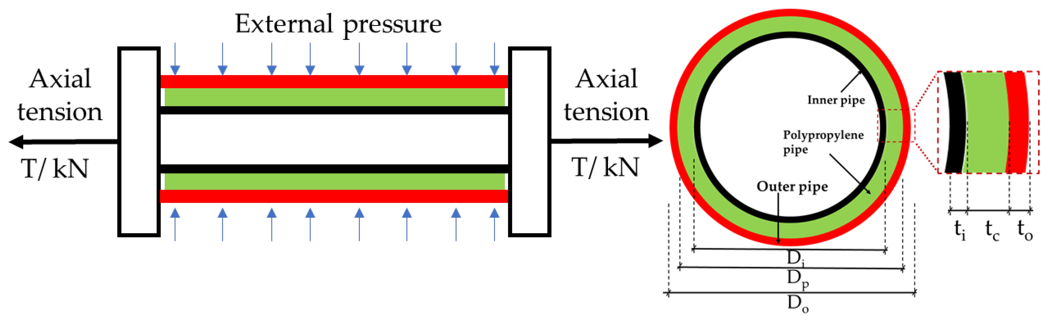
2.2. Geometric Features of Pipes

Since geometric imperfection is a key parameter affecting the collapse capacity of the deep-sea pipeline, the specimen samples were fixed with two vises, and the profiles of all samples were recorded using RA7320 (portable arm coordinate measuring machine).
To better verify the accuracy of the numerical model, RA7320 PACMM, as shown in Figure 2b, was used to scan the external contour of the pipe, and the equivalent ovality of the pipe was obtained through the formula as follows:
Δ 0 = R max R min R max + R min
where Δ 0 represents the overall ovality, and R max and R min mean the maximum radius and the minimum radius.
The spatial coordinates of the probe were recorded by software PCDMIS as shown in Figure 3. The recording frequency is set to fixed interval sampling, and the ovality of pipes is collected. As shown in Figure 3, 20 cross-sections are established through points in ABAQUS, and then the whole model of the pipe is built by connecting each cross-section. The measuring range of RA7320 is 2.3 m, with the point repeatability accuracy of 0.03 mm and the spatial length accuracy of 0.042 mm. For more information about the device and measuring scheme, refer to the authors’ previous work [43,44].
Note that the diameter of the probe is 3 mm. When inputting the spatial coordinates, the data points should be offset by 1.5 mm along the radial direction to obtain the true pipe surface. The shape of the inner and outer pipe is measured, and different ovality is obtained. The Ultrasonic thickness gauge with a resolution of 0.01 mm was used to measure the pipe wall thickness. The measuring points were at the intersection of the grid, and the average wall thickness of the outer tube was 4 mm, while that of the inner tube was 3 mm.
In this experiment, 2 single-wall pipes of the control group and 6 sandwich pipes of the experimental group were tested. The geometric features and production method of pipes are shown in Table 1.

2.3. Material Test

According to GB/T 228.1-2010 [45], the uniaxial tensile test was carried out on the strip specimen to obtain the real properties of the material. The geometry of the tensile specimen is shown in Figure 4b. The material test is shown in Figure 4a, and the specimen is stretched with a uniaxial tensile machine.
The stress–strain relationship obtained in uniaxial tensile tests is shown in Figure 4b, which can be described by the Ramberg–Osgood equation as follows:
ε = σ E [ 1 + 3 7 ( σ σ y ) n 1 ]
where E is elastic modulus, σy is nominal yield stress, and n is the hardening parameter. The material parameters in the Ramberg–Osgood model are summarized in Table 2. The tension and compression tests were also performed for the polypropylene core layer. The material mechanical properties of the polypropylene core layer are shown in Table 3. The difference in the stress–strain curve is due to the different compositions of the raw materials [46].

2.4. Buckling Test

After geometry measurements, all the samples were put into the pressure vessel for collapse experiments. The test setup is shown in Figure 5. The main parameters of the inner diameter of the pressure vessel are 240 mm, and the total length is 4.453 m, with a pressure capacity of 110 MPa, which is suitable for buckling test of pipes with a length of 2.3 m and external diameters ranging from 8 to 76 mm. In addition, regular and random vibration loads can be applied in horizontal directions, and the frequency range of loading is 0.1~40 Hz, which can simulate the vibration behavior of pipe/beam under high external pressure and axial load.
Both ends of the pipe are sealed with the flange which is connected to the pressure vessel and hydraulic cylinder with bolts before the buckling test. The pressure vessel is then filled with water and pressurized with a hydraulic pump, which pumps very slowly into the vessel (maximum pressurization speed 2 MPa/s) to achieve quasi-static conditions and avoid strain rate effects [44,45,46,47]. The pressure in the vessel is monitored by a pressure sensor, and the collapse pressure is defined as the peak value before the pressure in the facility suddenly drops when instability of the pipe occurs. The hydraulic automatic propulsion and locking devices are used in both the entry and exit of the test chamber.
This experiment was divided into three groups of experiments.
In the first group, external pressure tests were performed on two single-layer pipes OUT1 and IN1 to test the collapse pressure of the inner and outer steel pipes. The flanges at both ends of the pipe are hinged, and the flanges can move along the axial direction of the pipe.
In the second group, the pipes SP1-1, SP1-2, and SP1-3 are put into the hyperbaric chamber, respectively, water is pumped into the hyperbaric chamber, and the pressure is loaded to 42 MPa, 43 MPa, and 45 MPa, respectively. After the pressure in the pressure chamber stabilizes, axial tension is applied to both ends of the pipeline until the pipeline collapses or the pressure inside the pressure vessel drops suddenly.
In the third group, the pipes SP2-1, SP2-2, and SP2-3 are put into the hyperbaric chamber, respectively, the same axial tension is applied to the pipe SP2-1 as SP1-1, and the same axial tension is applied to the pipe SP2-2 as SP1-2 pull. When the tension is stable and the axial tension remains unchanged, water is injected into the hyperbaric chamber. As the pressure in the hyperbaric chamber increases, the pipeline collapses when it reaches the ultimate pressure.

2.5. Result

As mentioned above, 8 pipelines were tested in this experiment. The following sections summarize the behavior of the pipes under external water pressure. Table 4 summarizes the ovality of the specimens, the collapse pressure, and axial tension of the experiment’s result. Figure 6b shows the time versus pressure curves for SP1-1 and SP2-1 test pipe specimens. Figure 7 shows the photos of the sandwich pipe after collapse. The following sections summarize the phenomena observed in each sample and discuss the main parameters that affect the test results.
Two loading path experiments were carried out on the sandwich pipe with the same geometric and material parameters, and the ultimate strength of the sandwich pipe was tested. By comparing the collapse pressure, the influence of different loading paths on the ultimate bearing capacity of the sandwich pipe was determined. By comparing the two groups of tests, it is proved that the loading path of adding water pressure first and then axial tension is more dangerous. It can be seen from Figure 6a that the test results of the two loading paths are significantly different when the diameter-to-thickness ratio and material parameters are the same. The collapse pressure of loading path P→T is 7.78% to 6.05% lower than that of T→P. Moreover, it was found that the axial force had a significant effect on the collapse pressure of the sandwich pipe. As the axial force increased from 49.21 kN to 143.67 kN, the collapse pressure dropped by 4.07% to 5.83%. This phenomenon will also be analyzed in the subsequent numerical simulation results.

3. Numerical Model and Validation

3.1. Geometry of the Initial Model

The 1/8 symmetric model is used in the parametric study to better observe the influence of the axial force and the diameter-to-thickness ratio on the collapse pressure. Irregularities on the surface of the pipeline will seriously affect the bearing capacity of the pipeline. Therefore, in the model validation part, the real data collected on the pipe surface were used to model, eliminate the influence of the pipe surface irregularity on the numerical simulation results, and verify the accuracy of the numerical simulation method and input material properties. When the influence of the outer contour of the pipeline is eliminated and the accuracy of the numerical simulation technology is verified, the same numerical simulation method was used to establish a simplified symmetric model in the parametric study section, which can better investigate the effects of axial force and diameter-to-thickness ratio on sandwich pipes.
For model validation, a sandwich pipe model with local imperfection was established within the framework of the nonlinear finite element code ABAQUS 6.14. General static was selected as the solver. The stress–strain relationship obtained in the uniaxial tension test is described by the Ramberg–Osgood equation in the FE models, which could be expressed as Equation (2). As shown in Figure 3, the geometry features of local ovality defects were the input sequence by Spline base on the test results. The actual shape profile of the ovality imperfection is obtained by connecting the sections with loft as shown in Figure 8. After establishing the model of the inner and outer steel pipes, the two models were combined and the middle layer of the inner and outer pipes was set to be polypropylene pipes. The same material parameters in the experiments are applied to the models. In the experiment, both ends of the pipeline are fixed, so all the degrees of freedom at both ends of the model are restricted in the numerical simulation. The eight-node linear brick and incompatible element C3D8I was used to describe the steel pipe, PP pipe. Meanwhile, self-contact with frictionless was chosen as the interaction between the inner face of the pipe. The normal direction contact between the polypropylene pipe and the steel pipe is set as frictionless and hard contact, and a default penalty function is set. Certainly, the bonding force between epoxy resin and steel pipe is very small. Epoxy resin mainly plays the role of filling pores and transferring force, which is generally defined as frictionless [46]. The numerical simulation results fit the experimental results with frictionless interaction definitions.
For the parametric study, the sandwich pipe models were simplified as an axisymmetric 1/8 model, as shown in Figure 9. In the parametric analysis, the overall ovality is used as the main parameter of the initial defect of the pipe, and the ovality is determined by Formula (2). The ellipse tool in ABAQUS is used to draw and create a sandwich tube. The contact condition of the sandwich pipe is completely consistent with the model in the verification part. The interaction between the steel pipe and core layer is defined by a penalty contact algorithm with no friction [31]. As shown in Figure 9, to save the calculation cost, the model is simplified to a 1/8 model. Two sides of the model are provided with symmetrical boundaries, respectively (U1 = UR2 = UR3 = 0, U2 = UR1 = UR3 = 0), one end connected to the flange is completely fixed (U1 = U2 = U3 = UR1 = UR2 = UR3 = 0), and the other end is a symmetrical boundary along the pipe axis (U3 = UR1 = UR2 = 0). The setting of boundary conditions is the same as Gong et al. [24]. The contact between the rigid plane of the model and the inner surface of the inner pipe is non-friction and hard contact, and the separation is allowed after the contact for the simulation of the process of pipe buckling propagation.

3.2. Mesh Independence Test

Based on the geometry and loading characteristics, one 1/8 FE model was established to investigate the collapse pressure of the sandwich pipe under external pressure. The end of the pipe is fixed, which simulates the dynamic response of the sandwich pipe when it is not subjected to additional axial tension in the experiment. Mesh independence is determined before model validation, and collapse pressure was used as an index of convergence. The results are shown in Table 5, and the meaning of each item is shown in Figure 9. It was observed that when the number of elements increased from 12,960 to 259,200, the collapse pressure deviation remained at 1%. Considering the accuracy and computational cost, No. 4 was used for further analysis.

3.3. Model Validation

For model validation, the same geometry as that used in experiments is applied. The experimental results are very close to the numerical simulation results. The predicted collapse pressure is compared with the experimental results (Table 6). The errors of Out1, In1, SP1-1, SP1-2, and SP1-3 were calculated by the following formula:
E r r o r = P C O N P C O E P C O E × 100 %
The errors of SP2-1, SP2-2, SP2-3 were calculated by the following formula:
E r r o r = T N T E T E × 100 %
It can be observed that the predicted collapse pressure is in good agreement with the experimental results, and most of the errors are within ±3%.
This verifies the accuracy of the finite element model when simulating two different loading paths of the pipe under axial tension and external pressure.

4. Parametric Study

In this section, various pipe models with different diameter-to-thickness ratios and ovality were established to obtain the collapse pressure based on the validated numerical model.
First, by changing the axial tension, the influence of different axial tension on the collapse pressure under different loading paths is determined. Then, the diameter-to-thickness ratio of the inner and outer pipes was changed, and the influence of the diameter-to-thickness ratio on the collapse pressure of different loading paths was studied. Finally, the initial ovality of the pipeline was changed, and the influence of the ovality of the pipeline on the collapse pressure was studied.

4.1. Effect of Axial Tension

Changing the collapse pressure and axial tension of the sandwich pipe, as shown in Figure 6, the influence of different paths on the collapse pressure of the sandwich pipe is between 0.3% and 4.9%. With the increase of the axial tension, the influence of the axial stress on the circular stress in the P→T loading path increases. The ovality of the pipe increases as the circular stress increases.
As shown in Figure 10a, the local ovality of the pipe is increased as the external water pressure and axial tension increases. As shown in Figure 10b, the ovality of the sandwich pipe increases when the axial tension increases, and the ovality of the yield section is smaller than that of the P→T path. The collapse pressure of the sandwich pipe depends on the ovality, so the increase in axial tension will have a greater impact on the collapse pressure of different loading paths.

4.2. Effect of Outer Pipe Diameter-to-Thickness Ratio

In this section, the influence of different outer diameter-thickness ratios on the collapse pressure of the sandwich pipe is studied. The outer pipe diameter-to-thickness ratios are chosen as 11.83, 15, 18.25, and 23.67. In these analyses, the geometric dimensions of the core layer and the inner pipe did not change; only the wall thickness of the outer pipe was changed, and the ovality of the outer pipe was maintained at 0.6%. The selected material parameters and contact conditions are the same as the model in Section 3. As shown in Figure 11, the black lines represent the influence of different loading paths on the load-bearing limit of the sandwich pipe. A total of 80% of the collapse pressure of the sandwich pipe without being affected by the axial force is selected as the external pressure loaded in the P→T path. The maximum tensile force in the P→T loading path is taken as the tensile force value in the T→P path. When the diameter-to-thickness ratio of the outer pipe is greater than 18, the difference in the collapse pressure of the sandwich pipe under different loading paths is less than 1%, which has little influence in actual engineering applications. However, as the depth of ocean development increases, the diameter-to-thickness ratio of sandwich pipe and risers is often less than 18 to ensure safety during operation.
It can be seen from Figure 11 that when the outer pipe diameter-to-thickness ratio is less than 15, the collapse pressure difference of the sandwich pipe is 2.88%. With the diameter-to-thickness ratio decreasing, the phase difference ratio has little change. Therefore, different loading paths have obvious effects on sandwich pipes with a diameter-to-thickness ratio of less than 18, and the collapse pressure values differ by 0~2.88%.

4.3. Effect of Inner Pipe Diameter-to-Thickness Ratio

In this part, the influence of different outer diameter-to-thickness ratios on the collapse pressure of the sandwich pipe is studied. The comparison of the inner pipe diameter-to-thickness ratio of 10, 12.75, 17, and 25.5 is made. In these analyses, the geometric dimensions of the outer tube and core layer did not change; only the wall thickness of the inner tube was changed, and the ovality of the inner tube was 0.86%. The selected material parameters and contact conditions are the same as the model in Section 3.
As shown in Figure 12, the black line represents the influence of different paths on the bearing capacity of the pipeline. A total of 80% of the collapse pressure of the sandwich pipe without the influence of axial force is selected as the external pressure in the P→T path. The maximum tensile force in the P→T loading path is taken as the tensile force in the T→P path. It can be seen from Figure 12 that with the decrease of the diameter thickness ratio, the collapse pressure of the pipeline increases, and the difference of the ultimate bearing capacity of the sandwich pipe under different loading paths becomes larger.
It can be seen from the black line that when the diameter-to-thickness ratio is greater than 17, the influence of different loading paths becomes smaller, and the difference is less than 1%. When the ratio of diameter-to-thickness is less than 12.75, the difference ratio does not change significantly. The influence of the inner diameter-to-thickness ratio on the ultimate strength of the sandwich pipe under different loading paths is in the range of 0~4.05%, which is greater than that of the outer pipe diameter-to-thickness ratio. Different loading paths have different effects on sandwich pipes with different diameter-to-thickness ratios. Therefore, for sandwich pipes with large inner pipe diameter-to-thickness ratios, the pipe is more likely to collapse under the P→T loading path.

5. The Result and Discussion

5.1. The Results of FE Models

Parameter studies were carried out on two different loading paths to supplement the experimental results. The model parameters are shown in Figure 13. The same diameter and wall thickness as the test pipe are chosen, and the ovalities of the inner and outer pipes are 0.60% and 0.86%, respectively. The collapse process of the pipeline under the combined action of external pressure and axial tension is shown in the P→T and T→P loading paths in Figure 13. As the axial tension increases, the influence of different paths on the collapse pressure also increases. Axial tension will greatly reduce the collapse pressure in any loading path. The collapse pressure of the P→T loading path is smaller than the collapse pressure of the T→P loading path. Therefore, the P→T loading path in actual engineering is more severe.

5.2. Discussion of the Two Loading Paths

When the sandwich pipe is subjected to the combined action of axial tension and external water pressure, the stress distribution of the failure section of the pipeline is shown in Figure 14. Figure 14a shows the stress and strain distribution of the inner and outer steel pipes when the pipe collapses. The stress value in the red box is significantly larger than other positions, the yield stress of the material has been reached, and a large displacement has occurred. The stress concentration position in Figure 14b is mainly located in the red box inside the core layer. Stress concentration occurs at point C, but the stress value is lower than the yield strength of polypropylene, and there is no major deformation. The stress concentration at point A and point B is an important cause of section failure. Considering that the stress concentration and displacement at point A are greater than at point B, the stress and displacement at point A are tracked to find the difference between the two loading paths.
When the sandwich pipe is subjected to axial tension and external water pressure, the stress at point A under the two loading paths is analyzed. As shown in Figure 15 and Figure 16, σs, σr, σc, and σa represent total stress, radial stress, circumferential stress, and axial stress, respectively. The value of σr did not fluctuate greatly before the pipeline collapsed and was much smaller than the values of σc and σa. Therefore, σc and σa dominate the von-Mises stress analysis. The relationship between σs, σc, and σa can be expressed by Formula (5):
σ s = σ c 2 + σ a 2 σ c σ a
Under the action of axial tension, the ovality of the sandwich pipe section changes small, and the axial stress increases rapidly. The stress at point A is mainly caused by the axial tension. On the contrary, under the action of external pressure, the circumferential stress of the pipe section increased rapidly, and the ovality of the section increased from 0.973% to 1.372%, an increase of 41%. In the second loading step of the P→T path, as the external water pressure is kept constant, the circumferential stress will increase with the increase of the axial tension; the stress at point A reaches the yield stress faster than the path T→P. In the path of T→P, it can be observed that as the tensile force increases, the circumferential stress hardly changes. When the section approaches yield, the circumferential stress begins to change significantly due to the large deformation. Therefore, the influence of the circular stress by the axial tension is the main reason for the different pressure-bearing capacities of the sandwich pipe in different paths.
As shown in Figure 15, the axial tension increases by 142.79 kN, the circular stress and von Mises stress increase by 107.54 MPa and 108.50 MPa, and the circular stress decreases by only 1.83 MPa. The axial stress contributes the most to the element stress. In the second step of loading, as the external pressure increases, the axial stress hardly changes. The circumferential stress increases from 1.83 MPa to 333.23 MPa, with an increase of 331.40 MPa. When the axial stress is 183 MPa, the von Mises stress reaches 273.63 MPa, the material yields at point A, and the ovality of the section increases rapidly with the increase in external pressure. The pipe collapsed when the ovality reached 3.54%, and the ability of the sandwich pipe to withstand water pressure dropped sharply. Additionally, due to the increase of external water pressure, as shown in Figure 16, the circular stress changes significantly, and the circular stress curve (purple) is almost the same as the von Mises stress curve (red). However, the external pressure increases the von Mises stress by 203.45 MPa, which is higher than the increase of the water pressure on the von-Mises stress in the T→P path. The circular stress of the section increases from 18.47 MPa to 73.06 MPa as the axial tension increases, which will lead to faster local yield at point A.
It can be seen from the ovality curve that when the tensile force increases to 84.88 kN, the von Mises stress at point A reaches the yield point, and the ovality begins to increase rapidly. During the T→P loading process, the pipe section began to deform greatly when the ovality reached 1.53%, while in P→T, the pipe deformed greatly when the ovality reached 1.37%. However, the ovality of the two loading paths is 3.87% and 3.53% when the pipe collapses, respectively. Obviously, the deformation of the pipe under the P→T path is greater. The collapse pressure of the sandwich pipe depends on the ovality of the pipeline during buckling, and the difference in the ovality is mainly caused by the increase of the circular stress. When the von Mises stress is the same, point A yields deformation. The circular stress in the two loading paths of P→T and T→P is 231.99 MPa and 183.75 MPa, respectively, with a difference of 26.25%. This also leads to the difference in the ovality under different paths when the pipe section yields.

6. Conclusions

The finite element model is in good agreement with the experimental results of the sandwich pipe under external pressure and axial tension. This paper also studies the influence of the two loading paths on the collapse pressure of the sandwich pipe, analyzes the point where the yield concentration occurs in the section, and explains the reasons for the difference. In addition, extensive parameter studies of different loading paths have been carried out through the finite element model, supplementing the experimental results. On this basis, the influence of the inner and outer pipe diameter-to-thickness ratio on the collapse pressure of the sandwich pipe under different loading paths is analyzed. The main conclusions are as follows:
(1)
The ultimate load of the sandwich pipe under the combined action of external pressure and axial tension is studied through eight groups of tests. It is verified that the ultimate load of the sandwich pipe with the same geometric parameters is different under different loading paths. Experiments show that the path of applying water pressure and then axial tension is more dangerous than the path of applying axial tension and then water pressure, and the influence range of different paths on the collapse pressure of the sandwich pipe is 4.07~7.78%.
(2)
The influence of two loading paths on the ultimate strength of the sandwich pipe is studied by using a finite element model. The results show that different paths lead to different stress changes in the cross-section of the sandwich pipe. In the P→T loading path, the external water pressure increases the ovality of the pipeline, and the axial tension increases the circumferential stress of the sandwich pipe, resulting in the local section of the sandwich pipe reaching the yield state faster. However, in the loading path of T→P, the axial tension has little effect on the circumferential stress, which results in a smaller change of ovality, and the sandwich tube has a higher ultimate strength.
(3)
The experimental results are supplemented by parametric studies. When the axial tension increases from 0 to 291.53 kN, the difference in collapse pressure under different loading paths increases from 0% to 4.9%. When the diameter-to-thickness ratio of the outer pipe increases from 12 to 24, the difference in collapse pressure under different loading paths is reduced from 2.88% to 0.6%. The increase of the diameter-to-thickness ratio of the outer pipe reduces the influence of different loading paths. When the inner tube diameter-to-thickness ratio increases from 10 to 25.5, the difference in collapse pressure under different loading paths is reduced from 4.05% to 0.86%. The increase in the inner tube diameter-to-thickness ratio will reduce the influence of different loading paths. The inner pipe diameter-to-thickness ratio has a greater influence on the collapse pressure than the outer pipe diameter-to-thickness ratio.

Author Contributions

Conceptualization, J.Y. and N.C.; Formal analysis, W.X. and S.J.; Funding acquisition, J.Y.; Investigation, S.X. and M.H; Methodology, W.X. and S.J.; Supervision, N.C.; Validation, W.X. and S.J.; Writing—original draft, J.Y., W.X. and S.J.; Writing—review and editing, W.X., S.J. and M.H. All authors have read and agreed to the published version of the manuscript.

Funding

This research was funded by the National Natural Science Foundation of China (Grant nos. 51879189 and 52071234).

Institutional Review Board Statement

Not applicable.

Informed Consent Statement

Not applicable.

Data Availability Statement

Not applicable.

Conflicts of Interest

The authors declare no conflict of interest.

References

  1. Dyau, J.Y.; Kyriakides, S. On the localization of collapse in cylindrical shells under external pressure. Int. J. Solids Struct. 1993. [Google Scholar] [CrossRef]
  2. Yu, J.; Wu, M.; Sun, Z.; Duan, J. Research progress of buckling propagation experiment of deep-water pipelines. Trans. Tianjin Univ. 2016, 22, 285–293. [Google Scholar] [CrossRef]
  3. Sun, C.; Zheng, M.; Soares, C.G.; Duan, M.; Wang, Y.; Onuoha, M.D.U. Theoretical prediction model for indentation of pipe-in-pipe structures. Appl. Ocean Res. 2019, 92. [Google Scholar] [CrossRef]
  4. Yu, J.; Wang, H.; Fan, Z.; Yu, Y. Computation of plastic collapse capacity of 2D ring with random pitting corrosion defect. Thin-Walled Struct. 2017. [Google Scholar] [CrossRef]
  5. Xue, J.; Wang, Y.; Yuan, D. A shear deformation theory for bending and buckling of undersea sandwich pipes. Compos. Struct. 2015, 132, 633–643. [Google Scholar] [CrossRef]
  6. Xia, M.; Takayanagi, H.; Kemmochi, K. Analysis of transverse loading for laminated cylindrical pipes. Compos. Struct. 2001, 53, 279–285. [Google Scholar] [CrossRef]
  7. Zhu, X.; Lei, Q.; Meng, Y.; Cui, X. Analysis of tensile response of flexible pipe with ovalization under hydrostatic pressure. Appl. Ocean Res. 2021, 108, 102451. [Google Scholar] [CrossRef]
  8. Yuan, L.; Kyriakides, S. Hydraulic expansion of lined pipe for offshore pipeline applications. Appl. Ocean Res. 2021, 108, 102523. [Google Scholar] [CrossRef]
  9. Yu, J.X.; Han, M.X.; Duan, J.H.; Yu, Y.; Wang, H.K. The research on the different loading paths of pipes under combined external pressure and axial tension. Int. J. Mech. Sci. 2019. [Google Scholar] [CrossRef]
  10. Liu, R.; Li, C.; Peng, B. Axial pipe-soil interaction during pipeline-walking analysis of pipelines placed on Bohai sand. Appl. Ocean Res. 2020, 99, 102133. [Google Scholar] [CrossRef]
  11. Zhang, X.; Pan, G. Critical force of upheaval buckling for imperfect subsea pipe-in-pipe pipelines on nonlinear foundation. Appl. Ocean Res. 2021, 110, 102593. [Google Scholar] [CrossRef]
  12. Zhang, X.; Duan, M.; Guedes Soares, C. Lateral buckling critical force for submarine pipe-in-pipe pipelines. Appl. Ocean Res. 2018, 78, 99–109. [Google Scholar] [CrossRef]
  13. Gowid, S.; Mahdi, E.; Renno, J.; Sassi, S.; Kharmanda, G.; Shokry, A. Experimental investigation of the crashworthiness performance of fiber and fiber steel-reinforced composites tubes. Compos. Struct. 2020, 251, 112655. [Google Scholar] [CrossRef]
  14. Huang, Z.; Zhou, Y.; Hu, G.; Deng, W.; Gao, H.; Sui, L. Flexural resistance and deformation behaviour of CFRP-ULCC-steel sandwich composite structures. Compos. Struct. 2021, 257, 113080. [Google Scholar] [CrossRef]
  15. Pan, D.; Chen, L.; Zhao, Q.; Chen, L.; Lin, M.; Li, C. Local buckling theoretical calculation method of the FRP foam sandwich cylinder under axial compression. Compos. Struct. 2020, 246, 112371. [Google Scholar] [CrossRef]
  16. Zhang, Z.; Yu, J.; Liu, H.; Chen, Z. Experimental and finite element study on lateral global buckling of pipe-in-pipe structure by active control method. Appl. Ocean Res. 2019, 92, 101917. [Google Scholar] [CrossRef]
  17. Estefen, S.F.; Netto, T.A.; Pasqualino, I.P. Strength analyses of sandwich pipes for ultra deepwaters. J. Appl. Mech. Trans. ASME 2005, 72, 599–608. [Google Scholar] [CrossRef]
  18. Castello, X.; Estefen, S.F. Limit strength and reeling effects of sandwich pipes with bonded layers. Int. J. Mech. Sci. 2007, 49, 577–588. [Google Scholar] [CrossRef]
  19. Xu, Q.; Gong, S.; Hu, Q. Collapse analyses of sandwich pipes under external pressure considering inter-layer adhesion behaviour. Mar. Struct. 2016, 50, 72–94. [Google Scholar] [CrossRef]
  20. Pasqualino, I.P.; Lourenc¸o, M.I.; Netto, T.A. Propagation of buckles in sandwich pipes under external pressure. Int. Conf. Offshore Mech. Arct. Eng. 2005, 41979, 609–617. [Google Scholar]
  21. Lourenço, M.I. Core Material Performance on the Propagation Pressure of Sandwich Pipes. In Proceedings of the ASME 2008 27th International Conference on Offshore Mechanics and Arctic Engineering, Estoril, Portugal, 15–20 June 2008; pp. 471–480. [Google Scholar]
  22. Fu, G.; Paz, C.M.; Chujutalli, J.A.H.; Lourenço, M.I.; De Lima, D.B.; Li, Y.; Filho, R.T.; Estefen, S.F. Sandwich pipes with strain hardening cementitious composites (SHCC). Numerical analyses. Proc. Int. Conf. Offshore Mech. Arct. Eng. OMAE 2014, 6A, 1–10. [Google Scholar] [CrossRef]
  23. Gong, S.; Wang, X.; Zhang, T.; Liu, C. Buckle propagation of sandwich pipes under external pressure. Eng. Struct. 2018, 175, 339–354. [Google Scholar] [CrossRef]
  24. Gong, S.; Li, G. Buckle propagation of pipe-in-pipe systems under external pressure. Eng. Struct. 2015, 84, 207–222. [Google Scholar] [CrossRef]
  25. Gong, S.; Wang, X.; Yuan, L.; Liu, C. The arresting performance of integral buckle arrestor for sandwich pipe systems. Int. J. Press. Vessel. Pip. 2019, 177, 103973. [Google Scholar] [CrossRef]
  26. Arjomandi, K.; Taheri, F. Elastic buckling capacity of bonded and unbonded sandwich pipes under external hydrostatic pressure. J. Mech. Mater. Struct. 2010, 5, 391–408. [Google Scholar] [CrossRef]
  27. Arjomandi, K.; Taheri, F. The influence of intra-layer adhesion configuration on the pressure capacity and optimized configuration of sandwich pipes. Ocean Eng. 2011, 38, 1869–1882. [Google Scholar] [CrossRef]
  28. Arjomandi, K.; Taheri, F. A new look at the external pressure capacity of sandwich pipes. Mar. Struct. 2011, 24, 23–42. [Google Scholar] [CrossRef]
  29. He, T.; Duan, M.; Wang, J.; Lv, S.; An, C. On the external pressure capacity of deepwater sandwich pipes with inter-layer adhesion conditions. Appl. Ocean Res. 2015, 52, 115–124. [Google Scholar] [CrossRef]
  30. Wang, Z.; Chen, Z.; He, Y.; Liu, H. Numerical study on lateral buckling of fully bonded sandwich pipes. Int. J. Steel Struct. 2017, 17, 863–875. [Google Scholar] [CrossRef]
  31. Garg, A.; Chalak, H.D. A review on analysis of laminated composite and sandwich structures under hygrothermal conditions. Thin-Walled Struct. 2019, 142, 205–226. [Google Scholar] [CrossRef]
  32. Fabian, O. Collapse of cylindrical, elastic tubes under combined bending, pressure and axial loads. Int. J. Solids Struct. 1977. [Google Scholar] [CrossRef]
  33. Kyriakides, S.; Chang, Y.C. On the effect of axial tension on the propagation pressure of long cylindrical shells. Int. J. Mech. Sci. 1992, 34, 3–15. [Google Scholar] [CrossRef]
  34. Nogueira, A.; Tassoulas, J.L. Finite element analysis of buckle propagation in pipelines under tension. Int. J. Mech. Sci. 1995, 37, 249–259. [Google Scholar] [CrossRef]
  35. Kyriakides, S.; Babcock, C.D. Large deflection collapse analysis of an inelastic inextensional ring under external pressure. Int. J. Solids Struct. 1981, 17, 981–993. [Google Scholar] [CrossRef]
  36. Madhavan, R.; Babcock, C.D.; Singer, J. On the collapse of long, thick- walled tubes under external pressure and axial tension. J. Press. Vessel. Technol. Trans. ASME 1993, 115, 15–26. [Google Scholar] [CrossRef]
  37. Bai, Y.; Igland, R.; Moan, T. Tube collapse under combined pressure, tension and bending loads. Int. J. Offshore Polar Eng. 1993, 3, 2–121. [Google Scholar]
  38. Bai, Y.; Igland, R.T.; Moan, T. Tube collapse under combined external pressure, tension and bending. Mar. Struct. 1997. [Google Scholar] [CrossRef]
  39. Bai, Y.; Hauch, S. Collapse capacity of corroded pipes under combined pressure, longitudinal force and bending. Int. J. Offshore Polar Eng. 2001, 11, 55–63. [Google Scholar]
  40. Madhavan, R. On the Collapse of Long Thick-Walled Circular Tubes Under Biaxial Loading; California Institute of Technology. Ph.D. Thesis, California Institute of Technology, Pasadena, CA, USA, 1988. [Google Scholar] [CrossRef]
  41. Tamano, T.; Inoue, Y.; Miniura, H.; Yanagimoto, S. Examination of commercial casing collapse strength under axial loading. J. Energy Resour. Technol. Trans. ASME 1982, 104, 343–348. [Google Scholar] [CrossRef]
  42. Yu, J.X.; Sun, Z.Z.; Liu, X.X.; Zhai, Y.X. Ring-truss theory on offshore pipelines buckle propagation. Thin-Walled Struct. 2014. [Google Scholar] [CrossRef]
  43. Wang, H.; Yu, Y.; Yu, J.; Xu, W.; Chen, H.; Wang, Z.; Han, M. Effect of pitting defects on the buckling strength of thick-wall cylinder under axial compression. Constr. Build. Mater. 2019, 224, 226–241. [Google Scholar] [CrossRef]
  44. Wang, H.; Yu, Y.; Yu, J.; Duan, J.; Zhang, Y.; Li, Z.; Wang, C. Effect of 3D random pitting defects on the collapse pressure of pipe—Part I: Experiment. Thin-Walled Struct. 2018. [Google Scholar] [CrossRef]
  45. GB/T 228.1-2010 Metallic Materials Tensile Testing Part 1: Test Methods at Room Temperature, General Administration of Quality Supervision. In Inspection and Quarantine of the People’s Republic of China; China Standard Press: Beijing, China, 2010.
  46. An, C.; Duan, M.; Toledo Filho, R.D.; Estefen, S.F. Collapse of sandwich pipes with PVA fiber reinforced cementitious composites core under external pressure. Ocean Eng. 2014, 82, 1–13. [Google Scholar] [CrossRef]
  47. Wang, H.; Yu, Y.; Yu, J.; Wang, Z.; Li, H. Development of erosion equation and numerical simulation methods with the consideration of applied stress. Tribol. Int. 2019. [Google Scholar] [CrossRef]
Figure 1. Geometry of tubes and idealized loading adopted in experiment.
Energies 14 04866 g001
Figure 2. (a) RA 7320 Portable Arm Coordinate Measuring Machine. (b) Photos of geometric characteristics measuring.
Energies 14 04866 g002
Figure 3. Schematic scanning points.
Energies 14 04866 g003
Figure 4. (a) The uniaxial tension test. (b) Engineering stress–strain curves of the test sample.
Energies 14 04866 g004
Figure 5. (a) Longitudinal sectional view in the middle plane; (b) experiment setup.
Energies 14 04866 g005
Figure 6. (a) Collapse envelopes of different loading paths. (b) Pressure–time diagrams of tested specimens SP1-1 and SP2-1.
Energies 14 04866 g006
Figure 7. Photos after the sandwich pipes collapse.
Energies 14 04866 g007
Figure 8. (a) Schematic diagram of scanning point modeling process for model validation; (b) schematic diagram of boundary conditions.
Energies 14 04866 g008
Figure 9. Schematic of the meaning of each item is shown in Table 5.
Energies 14 04866 g009
Figure 10. Ovality changing history of the outer pipe. (a) P→T loading path; (b) T→P loading path.
Energies 14 04866 g010
Figure 11. Collapse pressure of sandwich pipe with different outer pipe diameter-to-thickness ratios.
Energies 14 04866 g011
Figure 12. Collapse pressure of sandwich pipe with different inner pipe diameter-to-thickness ratios.
Energies 14 04866 g012
Figure 13. Collapse envelopes of different loading paths.
Energies 14 04866 g013
Figure 14. The von Mises stress distribution of pipes’ cross-sections. (a) Outer and inner pipes’ cross-section; (b) core layer cross-section.
Energies 14 04866 g014
Figure 15. Stress changing history at integration point A (T→P loading path).
Energies 14 04866 g015
Figure 16. Stress changing history at integration point A (P→T loading path).
Energies 14 04866 g016
Table 1. Geometric features and production method of pipes.
Pipe No.Do/mmto/mmDi/mmti/mmDp/mmtc/mmLoading Path
Out173.293.96----P
In1--54.023.01--P
SP1-173.024.0254.023.0165.025.05P→T
SP1-273.004.0454.063.0165.115.10P→T
SP1-373.134.1554.173.1265.155.09P→T
SP2-173.084.0854.053.0465.085.10T→P
SP2-273.044.1254.093.0065.125.06T→P
SP2-373.054.0754.093.0565.045.06T→P
Do is diameter of outer pipe, To is thickness of outer pipe, Di is diameter of inner pipe, ti is thickness of inner pipe, Dp is diameter of polypropylene pipe, and Tc is thickness of polypropylene pipe.
Table 2. Material parameters of the tested specimens.
PipeE/Gpaνσy/MPaσu/MPanElongation/%
Outer pipe250.000.3217.441076.145.5946.77
Inner pipe211.710.3189.34988.425.6043.12
Table 3. Material parameters of the core layer.
MaterialE/Mpaνσu/MPaεfail
Polypropylene13300.4121.80.076
Table 4. Overview of ovality and collapse pressure of all tested specimens.
Type of PipePipe No.Outer Pipe Ovality (%)Inner Pipe Ovality (%)Collapse Pressure (MPa)Axial Tension (kN)
Outer PipeOut10.49-27.950
Inner PipeIn1-0.7828.100
Sandwich PipeSP1-10.600.4141.50143.67
Sandwich PipeSP1-20.420.5442.5094.45
Sandwich PipeSP1-30.590.6144.0749.21
Sandwich PipeSP2-10.320.5545.00143.67
Sandwich PipeSP2-20.500.3746.1294.45
Sandwich PipeSP2-30.320.7946.9149.21
Table 5. Mesh convergence test.
No.NhNpSminSmaxElement Number of Steel PipeElement Number of Core LayerTotal Element NumberP/MpaError/%
110154043202160648043.10−4.22
210253043202160648045.360.80
310452055802790837047.184.84
43025408640432012,96045.451.00
530253011,160558016,74045.150.33
630452086,40043,200129,60045.150.33
760154017,280864025,92044.92−0.17
860243022,32011,16033,48045.020.04
9604220172,80086,400259,20045.000.01
Table 6. Overview of geometry parameters and collapse pressure of all tested specimens.
Pipe No.Experiment Results
PCOE/MPa
Numerical Results
PCON/MPa
Experiment Results
TE/MPa
Numerical Results
TN/MPa
Error/%
Out127.9528.74002.83
In128.1028.11000.04
SP1-141.5041.5143.67142.16−1.05
SP1-242.5042.594.4596.11.75
SP1-344.0744.0749.2149.470.53
SP2-145.0045.15143.67143.670.33
SP2-246.1247.294.4594.452.34
SP2-346.9145.7349.2149.21−2.52
Publisher’s Note: MDPI stays neutral with regard to jurisdictional claims in published maps and institutional affiliations.

