Now, consider
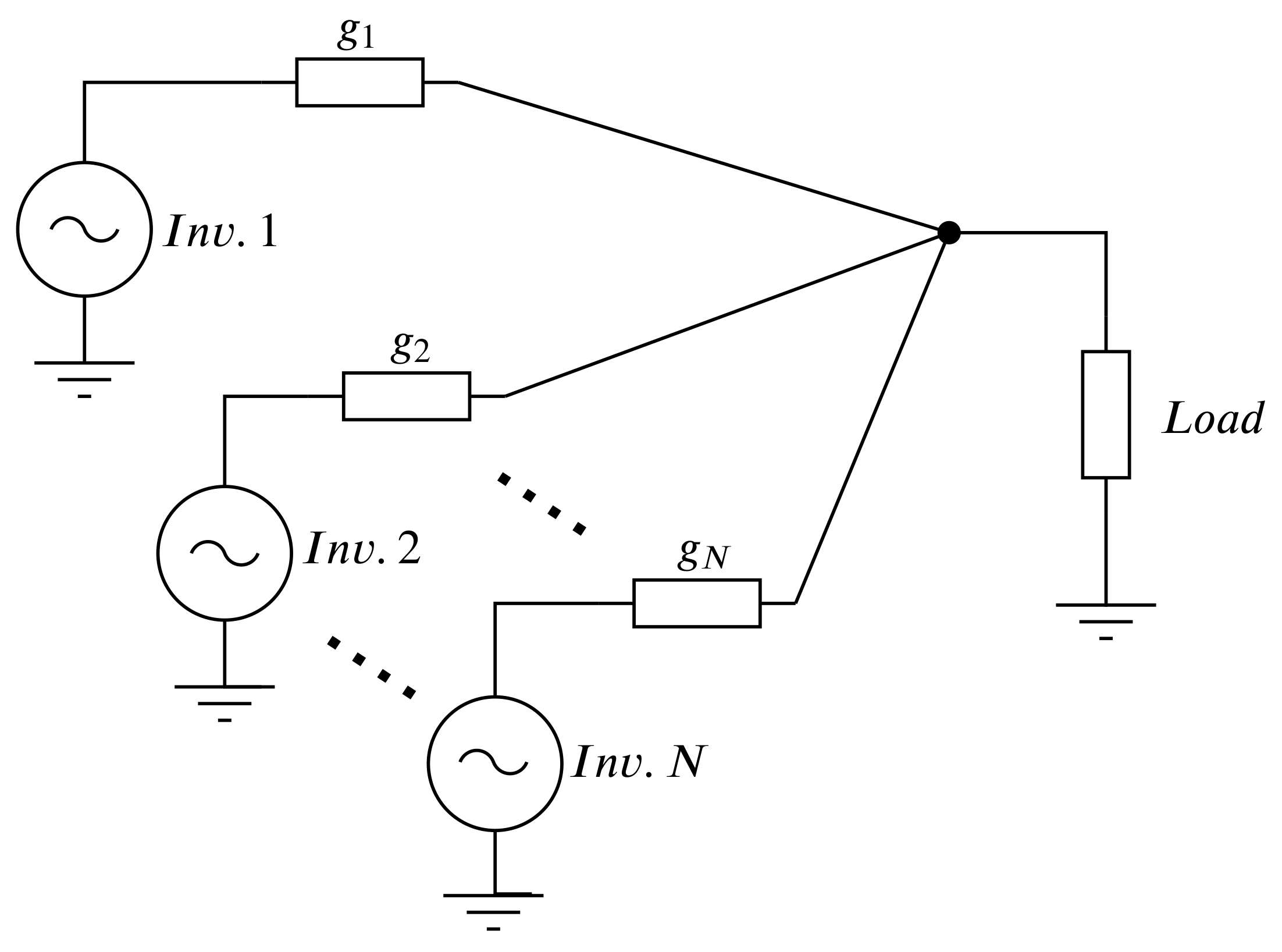
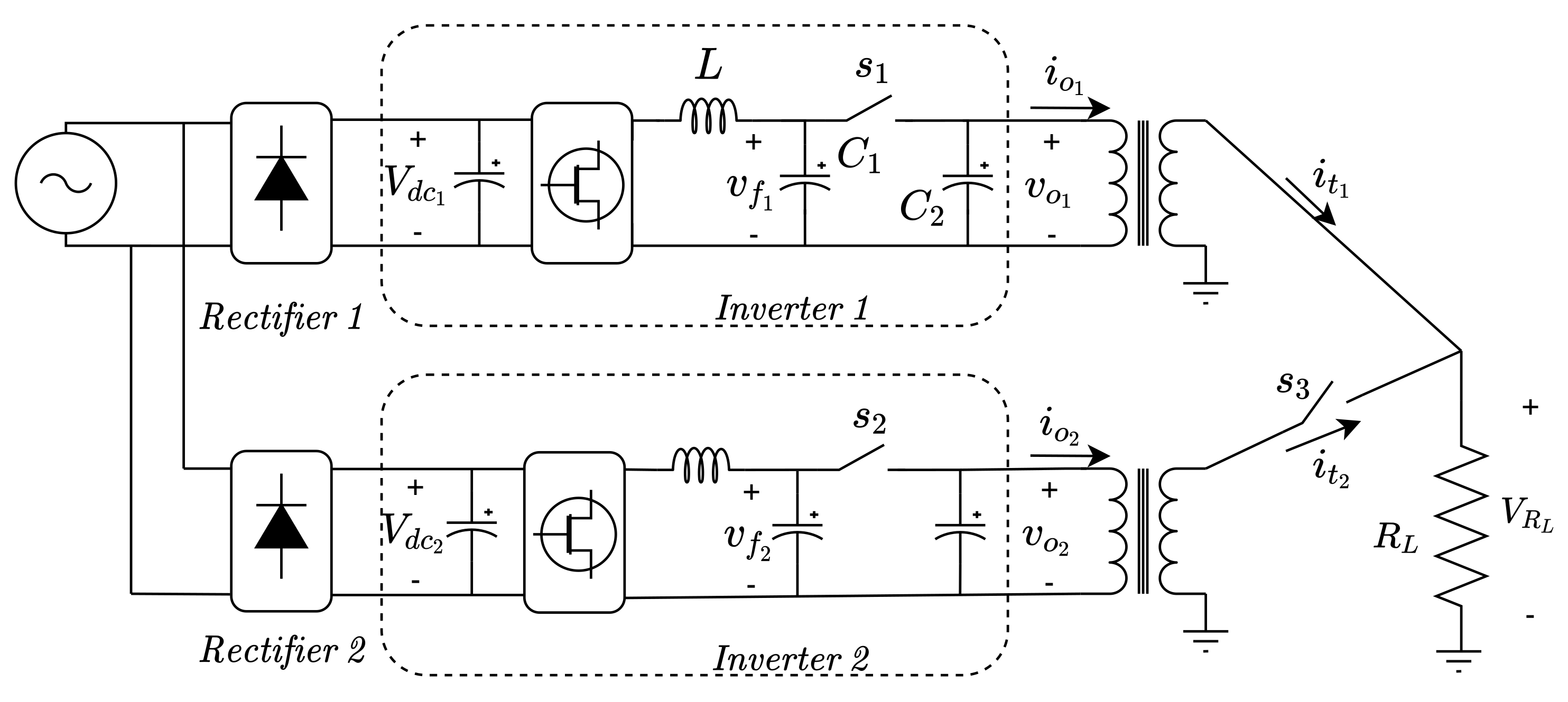
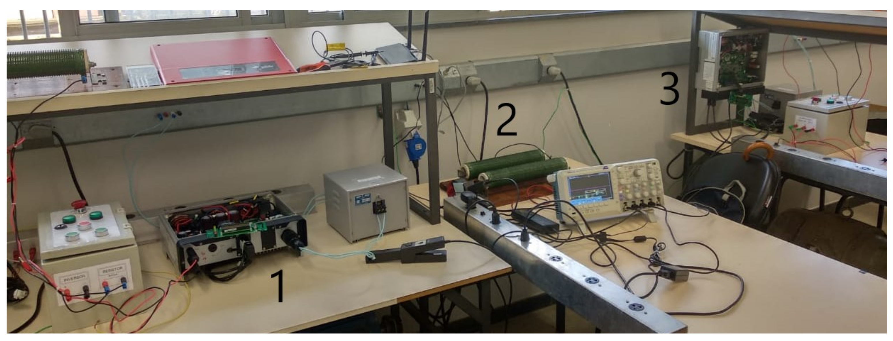
inverters controlled using this technique, with identical parameters, connected in parallel as shown in
Figure 1. The theoretical justification for the synchronization of a unknown but finite number of power oscillators in a symmetric electrical network is related to the
incremental passivity of the oscillators, together with the incremental passivity of the electrical network, in the sense briefly presented in
Appendix A. Using this concept it was shown that a sufficient condition for synchronization, among others, is that
where
is the passivity characteristic of the electrical network and
is the passivity characteristic of the linear time-invariant (LTI) system (
1) (see
Section 2.1). In this case, all units in
Figure 1 will synchronize naturally, sharing equally the load [
17]. It is important to emphasize that inequality (
3) is only a sufficient condition. In other words, even if the system violates this condition, it can still achieve synchronization in some cases. In Torres et al. [
17], although the connection impedances
were considered identical, the value of
or the load characteristic (resistive/inductive) does not require modifications to the method structure, as opposed to VFDM.
2.2. Practical VOC Parameters Selection
In Johnson et al. [
21], the average oscillator models are used to obtain parameters for a Van der Pol oscillator with cubic function, considering a quasi-stationary operation condition. However, the described procedure can be laborious and somewhat non-intuitive. The use of cubic function nonlinearity has some disadvantages, as third harmonic generation (see
Section 4.1). Besides, as reported in that work, an adaptation was required to eliminate an algebraic loop resulted from the use of approximate integration by means of the trapezoidal rule applied to discretize the smooth nonlinear differential equations. In order to overcome these drawbacks, a new approach for Voltage-Controlled Voltage Source Inverters (VCVSIs) control design, using VOC, is presented in this section. As described in
Section 2, an oscillator with saturation nonlinearity will be used. The parameters are selected to reduce harmonic generation. As the saturation is a piecewise linear function, this allows the use of exact discretization of the linear time-invariant systems that are used in the DSP numerical implementation.
From
Section 2, the necessary parameters to apply the VOC method are
,
,
,
, and
. The parameters
and
are associated with the frequency of
, while the amplitude is determined by the set of parameters
,
and
. Furthermore, it is desirable to satisfy inequality Equation (
3) such that
must be chosen in order to guarantee both sustained oscillations and synchronization of inverters. From Equation (
1), it is possible to infer that the current
also influences the amplitude of the oscillations. In the event that
, the load current will have little impact on voltage regulation. However, the more insensitive to the load current, the slower the synchronization process will become.
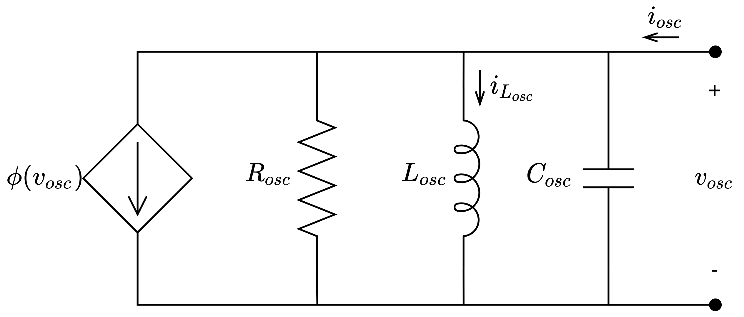
The describing function method is applied to the oscillator in
Figure 2. For a single-input single-output (SISO) nonlinear system, represented by a linear system with a nonlinear function feedback with
, there might be a periodic solution with a frequency and amplitude close to
and
a, if it is possible to solve the equation
where
is the frequency response of the LTI system Equation (
1) and
is the describing function obtained for the nonlinear function
([
32] Section 7.2). The expression in Equation (
9) is known as the harmonic balance equation. For memoryless, time-invariant and odd functions,
is real and can be calculated as
For the addressed problem,
corresponds to the saturation function, Equation (
2), with
. In this case, the solution of Equation (
10) is given by
where
. By inspection we have
As
is real, we can split Equation (
9) in two equations and solve separately as
The transfer function for the system in Equation (
1) is
Solving Equation (
14) for
it is found that the oscillation of the system, if it exists, must have an approximate frequency of
This result was already expected, as this is the central frequency of the
bandpass filter shown in
Figure 2. Solving now Equation (
13) using Equation (
17) we have
In addition, as
we can replace Equation (
18) in Equation (
12), thus
Therefore, if Equation (
19) is met, according to the describing function method, the system represented by Equation (
1), with feedback
and with
(disconnected from the electrical network), has a limit-cycle with amplitude
a and frequency
.
Although the describing function method is based on approximations and does not guarantee the existence of oscillations [
32], the condition expressed in Equation (
19) is consistent with that obtained in Equation (
8). In addition, the method is useful in determining an approximate relation between the parameters
,
,
, and the steady-state amplitude
a. On the other hand, it also gives an approximate relation between the steady-state frequency
and the parameters
and
.
In the previous analysis,
was considered to be zero. However, this condition is not realistic, as the main objective of the inverter is to supply power to the grid. To partially circumvent this issue, it is possible to imagine that a load connected to the oscillator is actually part of it, changing the values of the internal impedances. In the special case where the load is a pure resistance,
, the resulting equivalent resistance,
, of the new oscillator would be the computed from the parallel connection between
and
. This means that regardless of the value of
, the new value of the resistance of the oscillator would be less than the original value. Therefore, the load seen by the inverter when connected to the network has a direct impact on the oscillation condition of Equation (
19). For a given value of
, it is possible for the system to become asymptotically stable when connected to a load with a sufficiently small resistance value as pointed out in Equation (
8). This will be associated with the maximum allowed active power output, or rated power. Furthermore, as already discussed,
has an impact on the steady state amplitude,
a, and
must be used to define the minimum oscillation amplitude. Similarly, looking at Equation (
17), inductive and capacitive loads will directly impact the ultimate system’s oscillation frequency.
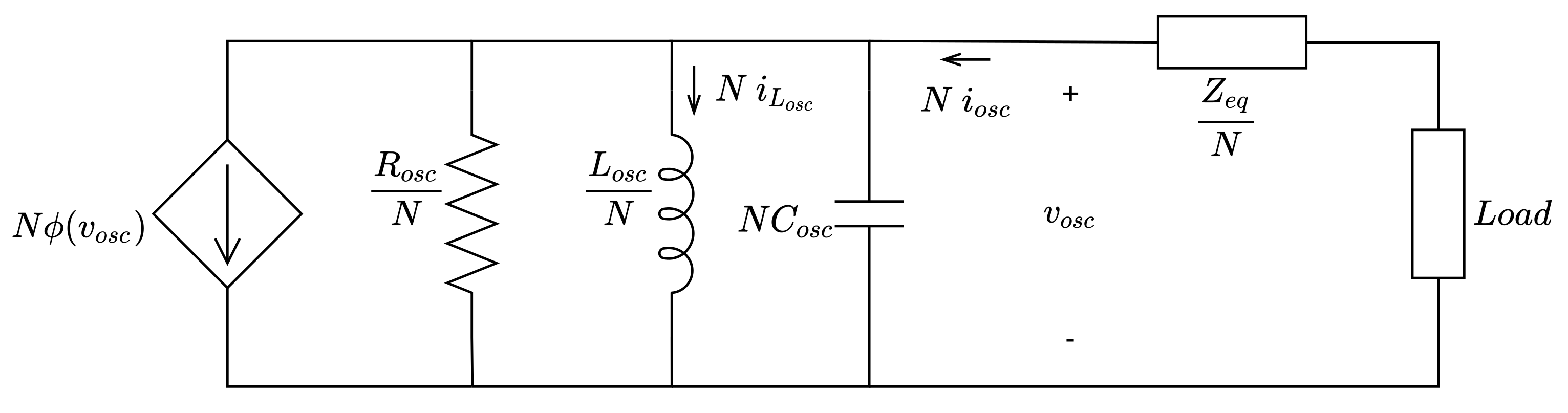
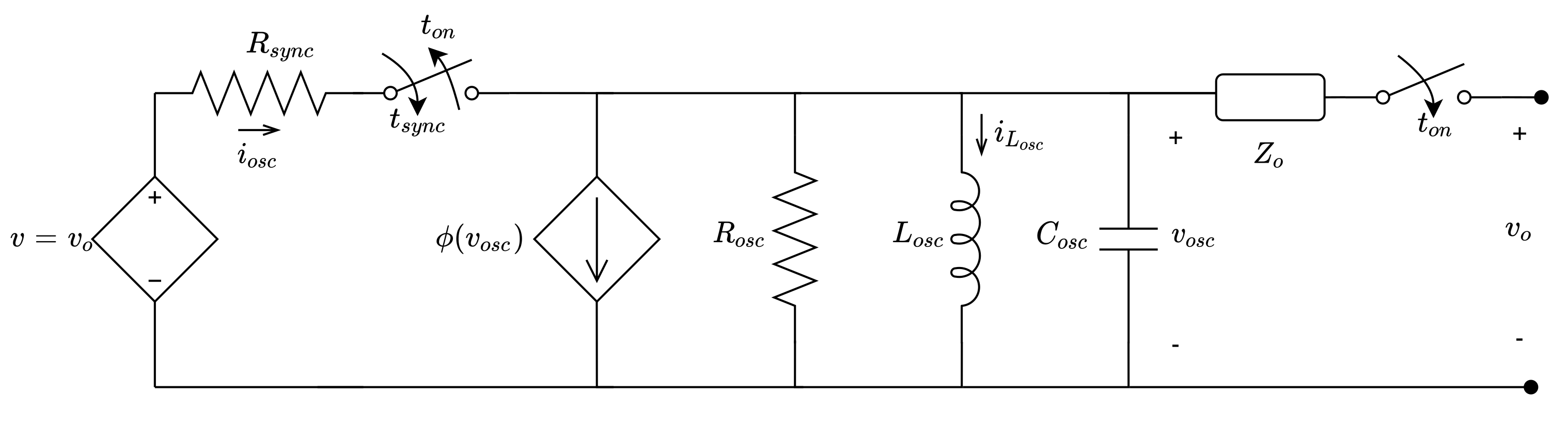
To formalize the previous discussion, consider that the
N inverters controlled by the VOC technique shown in
Figure 1 are synchronized. Using the fact that these oscillators are incrementally passive, it can be inferred that all states between oscillators are equal in steady state. In this condition, the microgrid can be represented as shown in
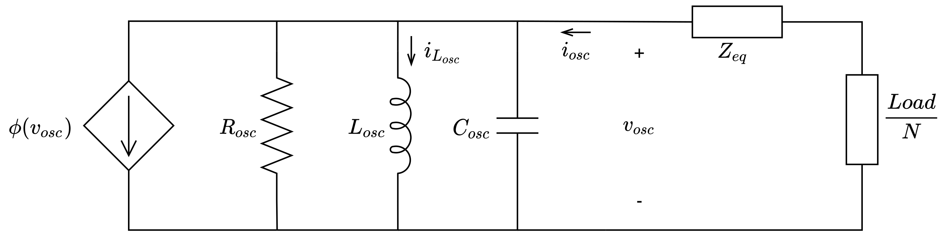
Figure 3. An equivalent circuit for a single inverter that is mathematically equivalent to the one in
Figure 3 is shown in
Figure 4.
Neglecting the harmonics that can be generated by the load or by
and considering that the system operates in steady state, that is, that phasor analysis can be applied, it is possible to decompose
in a parallel
or
circuit in order to keep
unchanged. In this case,
, thus
and
. In addition, the power absorbed by the grid is given by
and
. Therefore, it is possible to determine the values of
and
as
Considering what has been presented so far, it is possible to describe an algorithm for choosing the VOC parameters. The input data are the minimum and maximum voltage values ( and ), nominal frequency and maximum frequency deviation ( and ), and inverter rated power ( and ).
First, we will define
. The lowest bound is given by Equation (
8), but for the new equivalent oscillator we must use
and
. When the inverter delivers nominal power, the oscillator voltage will be minimum. From Equation (
20),
. Considering the synchronization condition expressed in Equation (
3) one has that
For simplicity, we choose
as
This is a good choice because there is no need to deal with the grid structure or impedance to calculate
. It is true that this does not guarantee synchronization, at least not without knowing the passivity characteristic
of the electrical network. This represents a compromise between a simplified design procedure, which is the main purpose in this work, and the computation of a property that depends on the exact knowledge of the electrical network parameters but that would guarantee the satisfaction of the sufficient, and therefore strong, condition (
3) for inverters synchronization. More information on the synchronization criteria and
calculation are found in Torres et al. [
17].
Using again the minimum voltage condition together with Equation (
11) and Equation (
18), for the value of
to be equal to
,
must be greater than or equal to
in Equation (
11). The maximum voltage condition will happen for the no-load condition. This time
must be equal to
. Looking at the second part in Equation (
11) we note that
must be less than one, otherwise this equation has no solution. Thus
must be less than
. Again, for simplicity we choose
Using the minimum value allowed for will maximize , which helps filtering high frequencies created by . Moreover, for nominal load operation, the peak values of will be close to then , and practically no harmonic is generated by the oscillator.
After defining
, and using the maximum voltage condition, it is possible to write the second part in Equation (
11) as
where
Using now Equations (
22) and (
24), it is possible to find
The reactive power delivered by the converter can be associated with an inductive or capacitive current. If
is inductive, the new inductance
will be less than
and the system frequency will be greater than the nominal frequency
; in this case,
. On the other hand, with
capacitive,
will be greater than
and the frequency will be less than the nominal frequency; in this case,
. From circuit theory, it is known that
Applying these relations to Equations (
27), (
28) and (
20), remembering that
and
, it is possible to write
As Equation (
17) must also be satisfied with
, it is not possible to satisfy Equations (
29) and (
30) simultaneously. However,
must be maximized in order to minimize the filter pass band, given by
The lower the value of
, the lower is the voltage harmonic distortion due to the nonlinear function
.
is calculated again starting from Equation (
17) using Equation (
29). The result is given by
must be chosen from
. Comparing Equations (
30) and (
32) it can be concluded that
, so (
32) should be used. Once
has been determined, the value of
can be calculated using
We can summarize the presented method as follows:
First, define the input parameters
,
,
,
,
, and
. Acquire the parameters from the inverter and from the microgrid (the inverter rated power and grid voltage and frequency). Define the aspects of power quality for your application. What is the minimal and maximum voltage amplitude and frequency allowed on your system? A good starting point is to use
and
and
. Besides, some regulation or standard can be used to drive this choice [
33].
Use
to calculate
with Equation (
23).
Use
to calculate
with Equation (
25).
Use
from previous step,
, and
to calculate
and
with Equation (
26).
Use
,
and
to calculate
with Equation (
32).
Use
from previous step and
to calculate
with Equation (
33).
In
Section 4, an example is presented with the actual parameters extracted from an implemented test setup.


 ,
, 


