1. Introduction
Induction motors are commonly used as industrial drives due to their cost, reliability, and self-starting advantages. They are composed of many mechanical parts such as stator windings, slots, rotor bars, shafts, and bearings that might occur in machine faults. Bearing and shaft-related failures are gradually decreasing as the manufacturing process improves. However, inter-turn faults (ITF) are still one of the frequent induction motor faults [
1,
2]. The surface of the stator magnet wire is very thinly coated with insulation material, and it is multiply wrapped in slots to induce high magnetomotive forces. However, the magnet wire insulation layers are not permanent and can be easily lost under various stresses, the so-called “TEAM” stresses as a state in [
3,
4,
5,
6,
7,
8]. Because ITFs are accompanied by heat generation, it is essential to detect the ITFs incipiently, unlike other machine faults. Otherwise, the ITFs worsen the insulation layer and expand the ITF spot. As a result, the overheated winding by the fault current could cause fatal damage to the motor. In many applications, such as industrial manufacturing, wind power generation, and electric vehicles, in which reliability is the most crucial factor, accurate ITF detection and diagnosis methods are essential.
ITF detection methods have been studied for over 30 years, and, generally, because of the simplicity and low cost, motor current signal analysis (MCSA) has been preferred to diagnose and detect stator ITFs [
9,
10,
11]. In MCSA, stator ITFs can be detected by the third stator current harmonic and slot harmonics frequency. This method is not sensitive in the low severity fault and cannot identify the stator fault since it is tough to distinguish the fault signal from the noise. Additionally, each machine requires large quantityof pretest datasets to apply the diagnosis methods based on MCSA.
Extended Park’s vector approach (EPVA) and the negative sequence current monitoring were studied for stator ITF detection as a more sensitive method [
12,
13,
14,
15]. In EPVA, the calculated frequency spectrum from Park’s vector is analyzed with a fast Fourier transform. Stator faults are diagnosed by the amount of the second and fourth harmonic current increase. Furthermore, the negative sequence current monitoring method uses asymmetry components for the stator faults diagnosis [
16,
17]. However, in an industrial motor operating system, most components have inherent asymmetry from winding placements, input grid voltage, phase resistance, etc. Particularly, harmonics and unbalanced components of the input grid voltage make fault diagnosis inaccurate.
Flux-based monitoring methods provide fault diagnosis using hall effect flux sensors or observer coils inside the motor [
18,
19,
20]. Compared with MCSA methods, flux monitoring methods show high performance and reliability in detecting the stator fault in low-level severity, but additional flux sensor and pretest data are required. Therefore, it can also be a burden in terms of price.
As mentioned above, most of the stator fault detection and diagnosis methods have been performed through signal analysis by imbalance component due to the stator faults, not based on the model. Therefore, to identify accurate fault severity, much pretest data accumulation is necessary for each machine, which is a significant burden in implementing the diagnosis method. Model-based ITF diagnoses have been studied in [
21,
22,
23] to overcome this problem. The stator faults can be identified with the severity factor from its eccentricity by stator faults using the equation of a 3-D ellipse in phase currents [
18,
19,
20,
21]. Furthermore, in [
22], the negative sequence equivalent circuit model with ITF was derived in the steady-state, and this model was applied to the ITF detection scheme using a feedforward neural network (FFNN) in [
23]. In recent papers, fault diagnosis methods were studied using a technique that is a growing variant of the curvilinear component analysis neural network in [
24], and the convolutional neural network (CNN) was utilized in the development of intelligent inter-turn fault diagnostic tools in [
25,
26]. However, even if induction motor models were proposed in these studies, these previous models were commonly induced with two-pole motors or a simple equivalent circuit based; thus, it is difficult to establish the fault severity standard and estimate fault parameters.
In this paper, the relationships between the severity of the ITF and additional negative sequence currents and copper loss generated in the fault spot are analyzed with the induction motor ITF model presented in part I [
27]. The ITF diagnosis and fault severity estimation method are proposed based on the analyzed negative sequence current deviation. In experiments, the input grid voltage is measured in real time to calculate the negative sequence current in the case of a healthy motor. The calculated negative sequence subtracted from the measured one is used as the fault signal by the ITF. The proposed ITF diagnosis method is verified under various fault conditions, and these show the feasibility of the detection method even in a low-level fault degree.
2. Negative Sequence Current and Copper Loss Analysis of Induction Motor with ITF
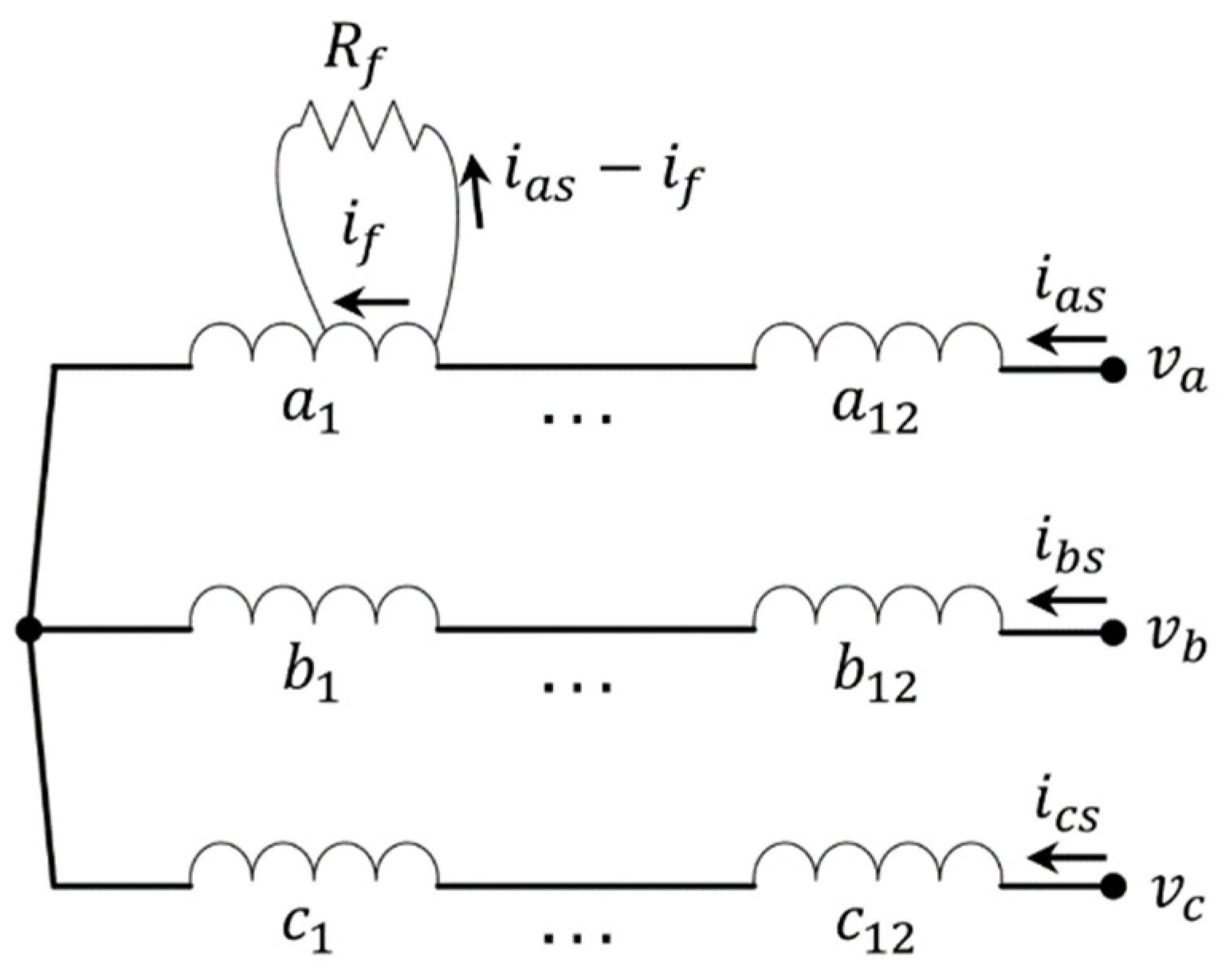
Figure 1 shows a winding configuration of a 4-pole 36-slot induction motor with an ITF. Here,
,
, and
denote the windings of each phase, and
and
denote the stator phase currents and voltages, respectively.
and
are fault resistance and fault current. When an ITF occurs in
winding, a part of the stator winding is short-circuited, as shown in
Figure 1. The voltage induced at fault closed-circuit generates a high fault current
due to the low impedance of the fault closed circuit; therefore, the three-phase balanced impedance becomes unbalanced. Particularly, the effect of the fault is reflected in the three-phase current when the motor is operated under the three-phase balanced voltage. Most of the components of unbalanced currents are the negative sequence current, and the worse the fault is, the more negative sequence current invokes; this was verified through simulations and experiments with the proposed fully described and the simplified model in part I [
27]. The derived voltage equation of the fully described ITF induction motor model is shown in Equation (1), where
,
,
,
,
,
, and
denote a pole number, number of windings per phase, the rotor position angle, stator resistance, rotor resistance, stator d,q-axis voltage, stator d,q-axis current in the stator stationary reference frame, and rotor d,q-axis current in the rotor stationary reference frame, respectively.
,
, and
are stator magnetizing inductance, rotor leakage inductance, stator one slot winding magnetizing, and stator one slot leakage inductance, respectively.
,
, and
are healthy turn ratio, stator inter-winding coupling factor, Fourier coefficients of the winding coupling factors between the rotor winding and the fault winding, respectively. With (1), the transient and steady-state response can be simulated.
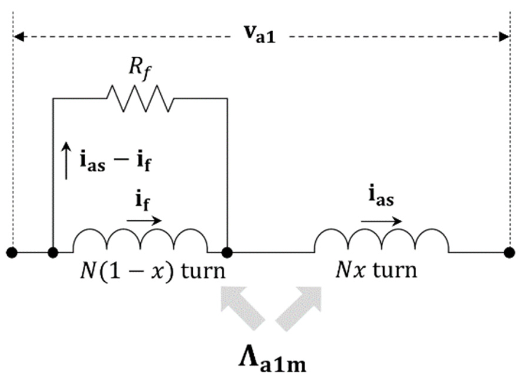
Figure 2 shows a circuit of
winding with an ITF. Here,
denotes the coupled
winding flux linkage from other stator windings (
,
, and
and the rotor windings (
);
is
-phase current in the complex domain. Analyzing under the steady-state condition, they are assumed as constant complex values. Considering the faulty
winding circuit, the steady-state fault current
can be derived as (2).
From (2), the fault current
is defined by fault parameters
and
. With (2), the
winding flux linkage
with the ITF can be expressed as (3).
The first and the second term on the right-hand side of (3) represent the healthy
winding flux linkage without any ITF. Hence, only the third term describes the distorted
winding flux linkage by the ITF and invokes the unbalanced three-phase current and the distorted stator and rotor flux linkage. This is the only cause of all flux distortion and fault signal generation. Note that it is a function not of specific fault parameters, i.e.,
x (healthy turn ratio) and
(fault resistance), but of
, which is a function of them.
was first introduced as an ITF severity index of a permanent magnet synchronous motor in [
28] and it was proven that a given
can represent the ITF influence without both specific
x and
information.
In the same manner as a derivation of (3), the coupled flux linkage
from the
winding to other windings can be obtained using the function of
as follows:
is the total flux linkage which can be coupled with other windings. The specific coupled flux linkage should consider the turn ratio and the magnetic coupling ratio. From (4), the faulty winding affects other windings as a form of , and it is a function of the fault severity index , not of respective fault parameters. This implies that the distortion of the coupled flux linkage from the faulty winding is resolved by . Hence, the ITF effect on other stator and rotor windings is also defined by it, not the respective fault parameters. From (2), is resolved by both x and . However, the distorted coupled flux linkages are identical for the identical , regardless of x and .
With (2) and
Figure 2, the voltage distortion induced in the faulty
winding is derived as Equation (5).
Here, , healthy turn ratio of winding satisfies , and and represent the full and no ITF. and denote the winding voltage when the motor has an ITF and no ITF, respectively. From (5), it can also be seen that the distorted phase voltage is determined by not by respective values of x and . In (5), the distorted voltage by the ITF with a given phase current is presented. Conversely, if the motor with the ITF is operated under the three-phase balanced input voltage, the unbalanced component by the ITF must be reflected in the three-phase currents. Since the dynamic equation of the motor system is identical, these unbalanced currents are also determined by . Hence, will be a function of .
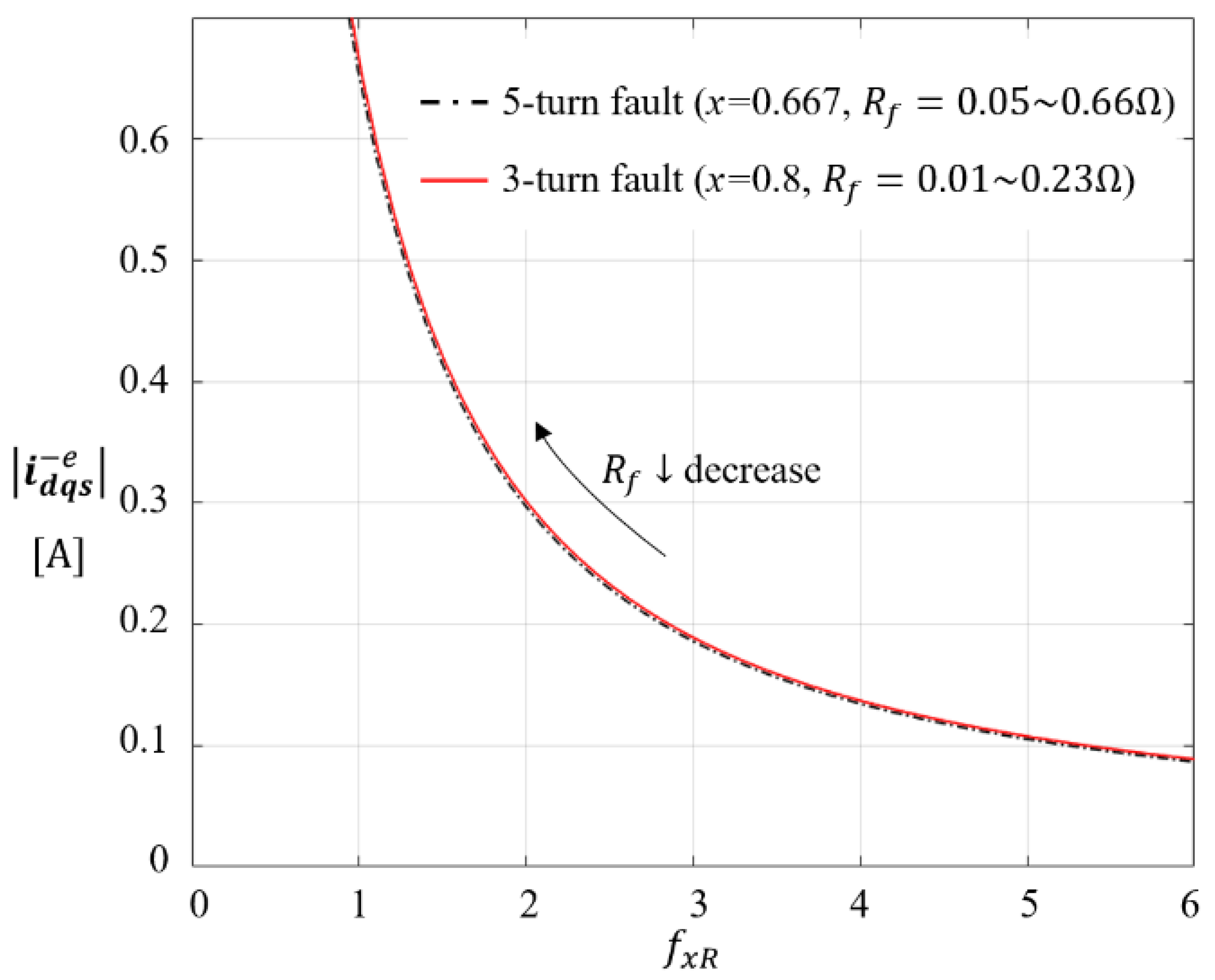
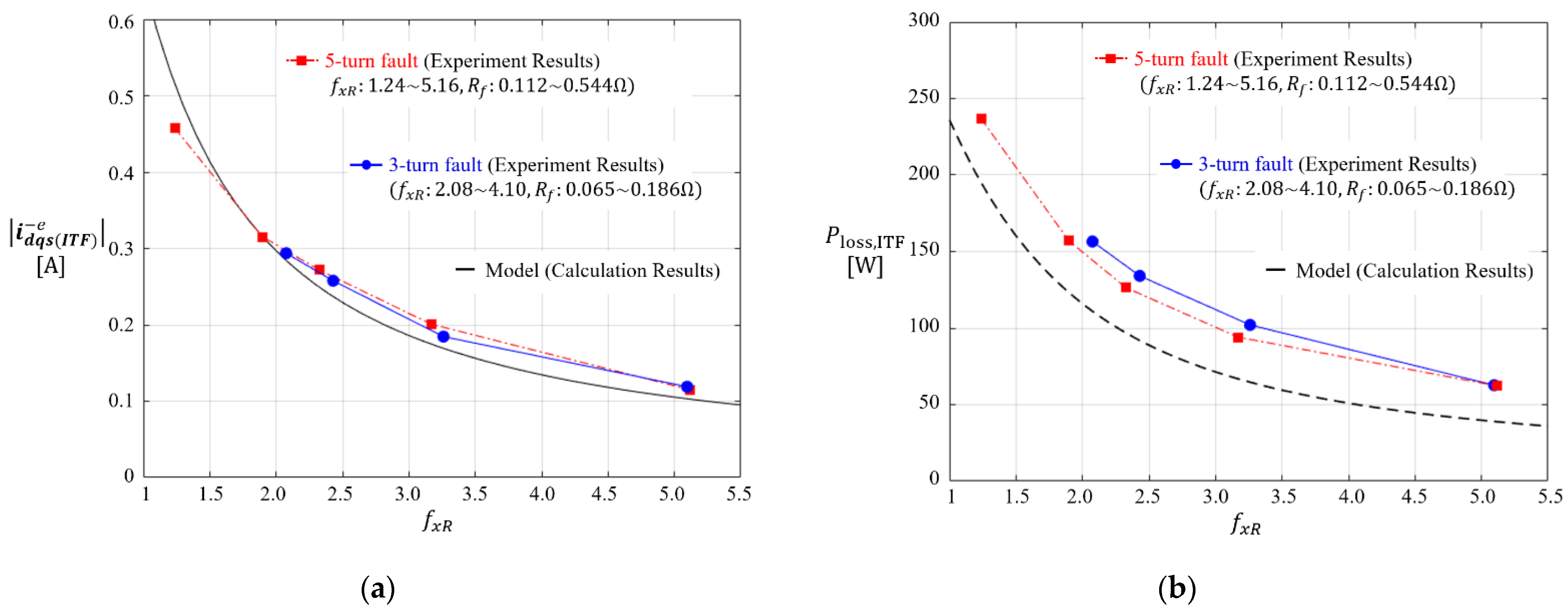
Figure 3 shows a plot of calculated negative sequence current
with fully described model (1) vs.
with varying
and fixed
(3-turns and 5-turns fault), respectively. The motor used in the calculation is a 4-pole 36 slot motor with 36 windings shown in
Figure 1, and a rated voltage 380 Vrms line–lineand 60 Hz, was applied under no load condition. In part I [
27], it was shown that the load condition has no dependency on the stator negative sequence current
by ITF. The motor parameters are listed in
Table 1. The solid red line and black dot-dashed line denote under 3-turns and 5-turns fault, respectively. The results show that the same negative sequence current magnitude occurs under the same
, regardless of each fault parameter,
x and
. It is also observed that the magnitude of the generated negative sequence current increases as
decreases. Therefore, the fault severity index
can be estimated using model (1) and obtained negative sequence current component.
However, it is hard to be sure that the same severity of fault occurs in the constant
without copper loss analysis because the generated negative sequence current is constant. The large fault current induces additional copper loss, which gives heat damage to the local neighboring winding. If the additional copper loss by the ITF is defined by
not the respective fault parameters, the fault effects on the neighboring winding could be calculated using estimated
. Therefore, it is essential to analyze the copper loss by the ITF. Under the constant
since the same positive and negative current is generated, the copper losses, occurring in the healthy windings (
), by the ITF is constant.
The entire copper loss generated in the ITF circuit can be divided into the main stator path with and the shorted circuit with , and derived as (6) using the calculated fault current . As (3)–(5), the copper loss generated in the ITF circuit is also defined by . Hence, after estimating the fault severity index , the heat damage by the ITF could be represented.
Theoretically, the minimum value of
is at least
, when
and
. In the case of the induction motor under study, when the fault turn numbers are 15-turns (
x = 0) and 1-turn (
x = 0.933), the minimum
become 0.09 and 1.35 at
, respectively.
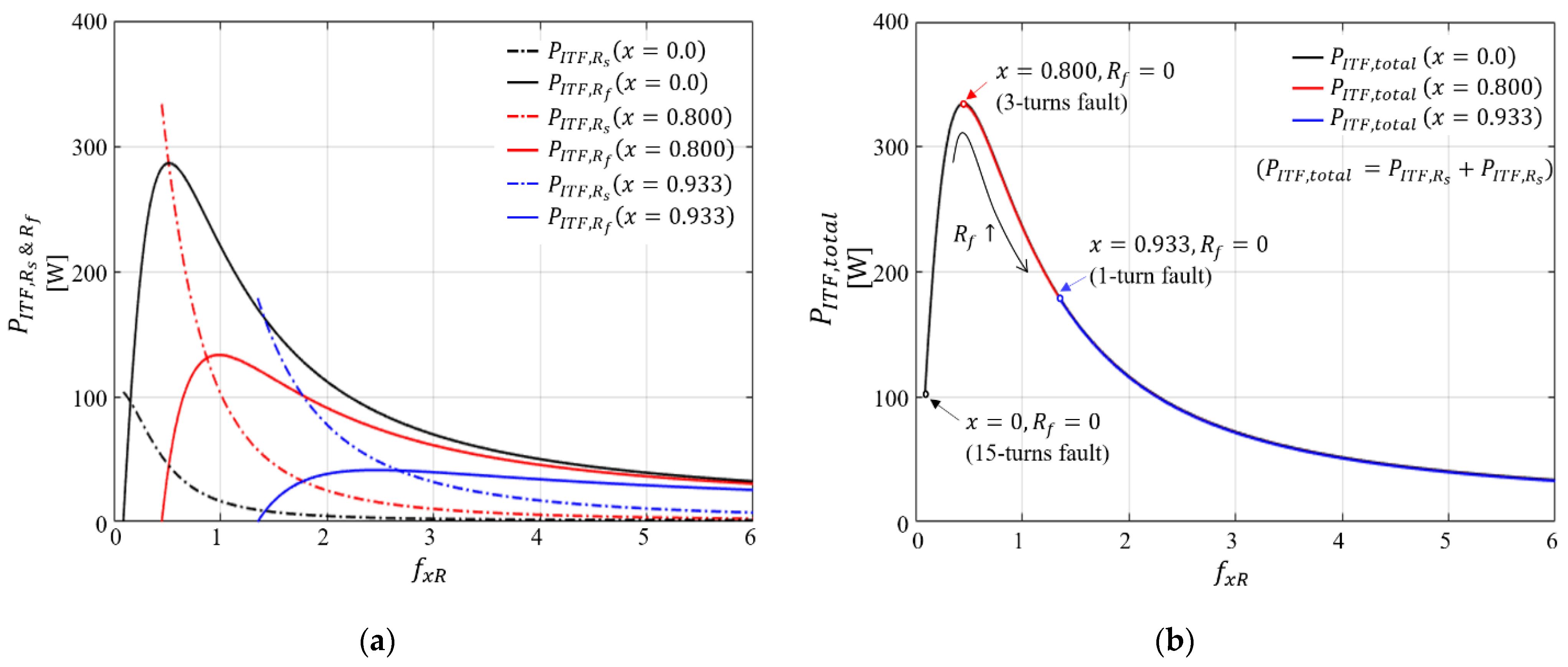
Figure 4 shows the calculated copper loss of the faulty winding with the fully described induction motor ITF model (1). In
Figure 4a, the solid lines represent the copper losses
generated at the main path of faulty winding with the resistance
when the healthy turn ratio
x is 0.0 (15-turns fault), 0.8 (3-turns fault), and 0.933(1-turn fault). The dashed lines denote the copper losses
generated at the shorted path of faulty winding with the fault resistance
. As shown in
Figure 4a,
and
have different values depending on fault parameters
and
. The lower the number of fault turns, the smaller the range of copper losses that can occur. A 1-turn fault has a minimum range of copper losses, as shown in the blue line of
Figure 4a.
.
Figure 4b shows the entire copper loss
, which is the sum of
and
when
x = 0.0, 0.8, and 0.933. These are almost identical regardless of fault turn number under constant
. However, because
has its minimum value depending on the healthy turn ratio
x, the copper loss ranges also vary.
has a maximum value at
. From
Figure 4, the degree of ITF can be determined by
, though the copper loss ranges differ depending on
x. As a result, it is possible to estimate the copper loss generated in the ITF circuit when
is estimated through the negative sequence current.
3. Fault Diagnosis Method and Fault Severity Index Estimation
The ITF diagnosis is essential to prevent rapid expansion of fault spots and unnecessary local temperature rise, resulting in a fire hazard. As shown in
Figure 3 and
Figure 4, when an ITF occurs, the magnitude of the negative sequence current and the copper loss is determined by the fault severity index
, not the specific fault parameters
and
. Furthermore, since the generated negative sequence current by the ITF increases as
decreases, this is used as a fault signal in the proposed diagnosis method. To calculate the additional power loss in the faulty winding,
is estimated based on the relationship between
and
in
Figure 3.
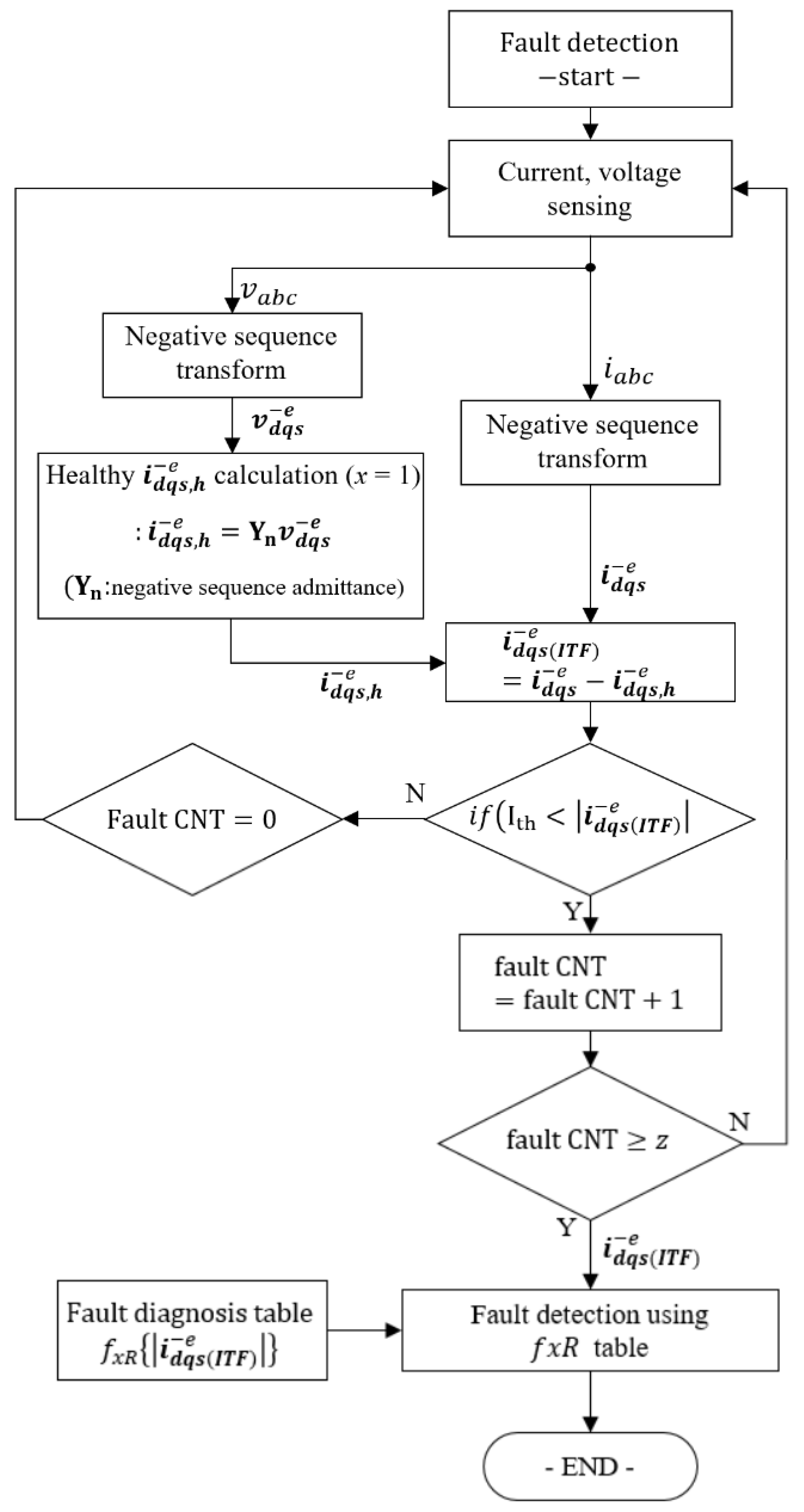
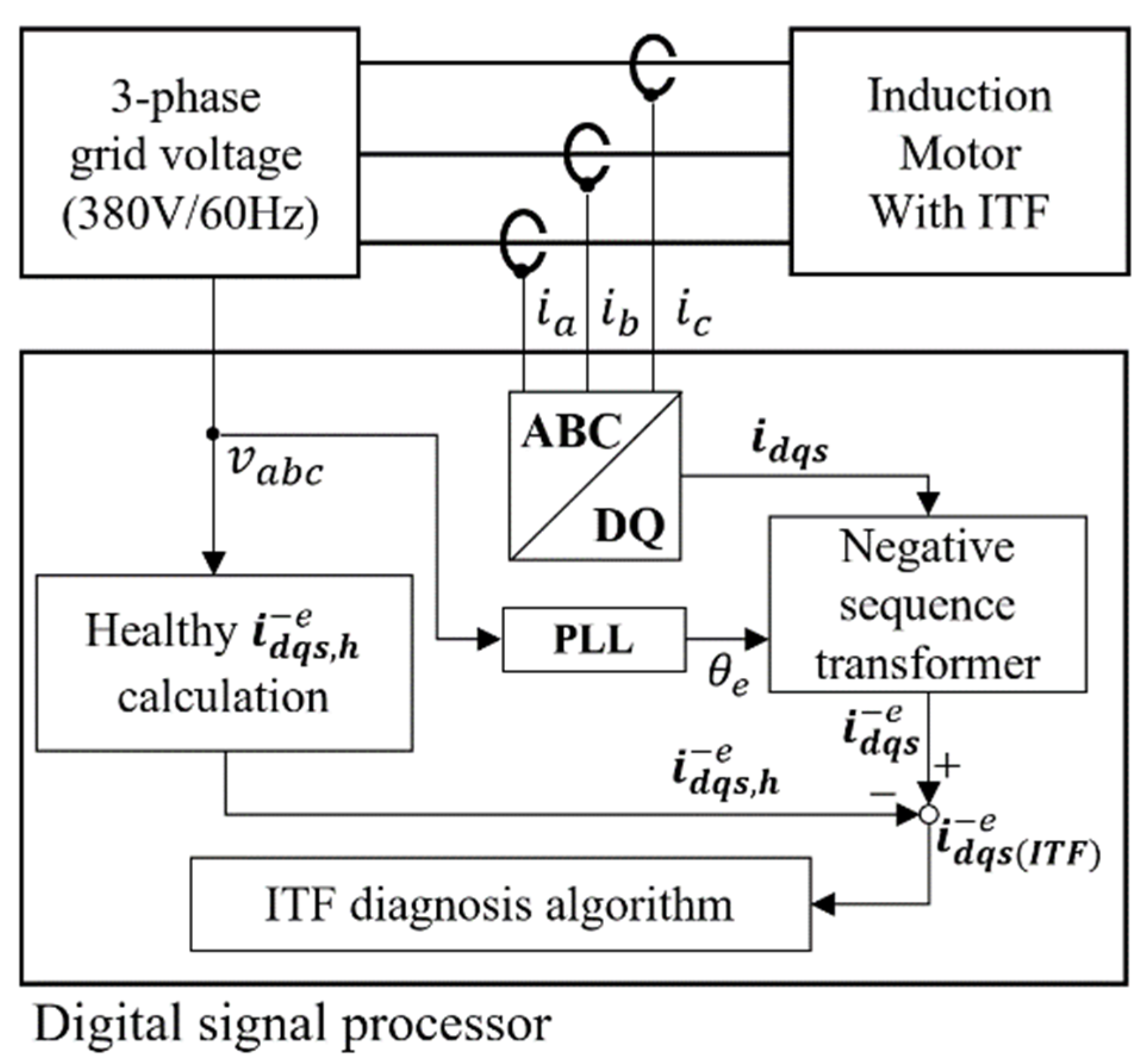
Figure 5 shows a block diagram of the proposed fault diagnosis method. The applied three-phase voltages
to the induction motor and three-phase currents
are measured. Three-phase currents
are converted into a negative sequence current
with phase voltage
, electrical angle
, and low pass filter. Even without the ITF, the negative sequence current may be caused by various factors. Particularly, unbalanced input three-phase voltage from the grid plays a great role when it comes to the unbalanced current generation. Although the negative sequence voltage effect of the grid is much insignificant compared with the ITF, it must be considered for accurate fault diagnosis. To establish precise criteria of the ITF by excluding the grid negative sequence voltage effect, the healthy motor current (
x = 1) is calculated in real time using the healthy motor negative sequence admittance
in [
29], with measured three-phase voltage
as an input voltage, and these are converted into the healthy negative sequence current
, which is a base value without the ITF.
To diagnose the ITF,
is compared with the healthy negative sequence current
in real time. The negative sequence current that occurs additionally by the ITF can be expressed as
. In the method,
denotes the threshold level of the negative sequence current to detect an ITF.
is set to the maximum value of
in the absence of ITFs. When
is greater than the threshold current
, the fault counter increases. However, if it is confirmed that the occurred negative sequence currents were caused by a temporary error rather than an ITF, the fault counter is initialized to zero. In this way, it is possible to ignore the negative sequence current caused by the spark current or measurement error. Finally, when the fault count is over a certain value z, it is judged as the ITF, and at this time, the fault degree
is estimated by
of
Figure 3.


