
Temperature Calculation, Test and Structure Improvement of Magnetic Coupling under High Slip


Abstract
:1. Introduction
- Study the temperature change of magnetic coupling in high slip;
- The heat loss equation of the magnetic coupling developed;
- Simulation analysis based on fluid-thermal coupling;
- Three kinds of heat dissipation improvement schemes are proposed and the best results are obtained.
2. Basic Structure and Principle
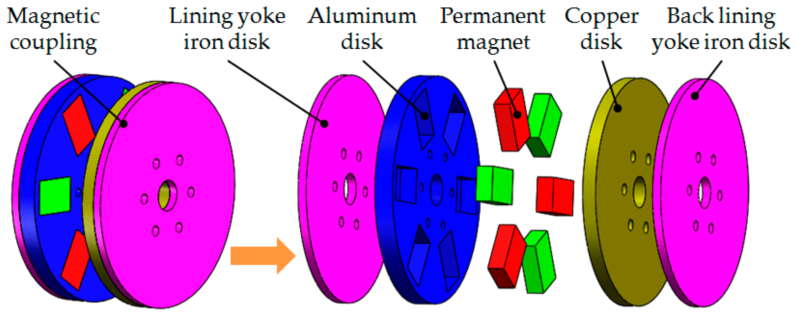
2.1. Structural Composition
2.2. Geometric Parameters and Material Properties
3. Heat Loss Analysis
4. Fluid-Thermal Coupling Simulation Calculation
4.1. Structural Composition
4.2. Assumptions and Boundary Conditions
- (a)
- In order to ensure the measurability of subsequent tests and the maximum possibility of temperature rise, the calculation mode of the magnetic coupler is set to a locked rotor state, that is, the load end is stationary, eddy current loss is completely used for heat generation, and the thermal power consumption is set to 46.3 W.
- (b)
- The eddy current loss generated is uniformly applied to the copper disk as a heat source, and the change of thermal conductivity of the copper disk, aluminum alloy, and yoke iron materials with temperature is considered, regardless of the thermal contact resistance between solids and the structural change due to physical expansion.
- (c)
- The surrounding air in the magnetic coupler structure is considered an incompressible fluid and determined as a turbulent state. The convection and heat dissipation coefficient of the solid surface is obtained through the simulation of fluid-thermal coupling.
- (d)
- A cylindrical air region is established to wrap the conductor rotor with a flange plate, input shaft, etc. It is set as the rotation region, with a speed of 200 r/min, and the grid calculation is finely drawn. Set the air gap between the permanent magnet rotor and the conductor rotor to be 4 mm, set the contact between the air and the magnetic coupler components to be a wall without sliding, set the external ambient temperature to 20.5 °C, and set the air gap to be at standard atmospheric pressure. The calculation field is a box which encloses the whole model. The dimensions in all directions are about 4 times the length of the model. As the slip is too large and the heat loss power is too large, the temperature of the structure will be in a high-temperature state after stabilization, which will cause high-temperature damage to it. Therefore, the transient solution mode is selected in this paper, and the calculation time is set as 600 s.
4.3. Flow Field Calculation Results
4.4. Calculation Results of Temperature Field
5. Test Verification
Establishment of Test Platform
6. Discussion
- 1.
- Scheme I: Installing heat sink
- 2.
- Scheme II: Half-round grooves are provided on the back lining yoke disk
- 3.
- Scheme III: Hybrid design
7. Conclusions
- The heat loss equation of the magnetic coupler is constructed, and the three-dimensional transient magnetic field model of the magnetic coupler is established. Through simulation, the distribution law of the induced eddy current of the magnetic coupler and the eddy current loss of power and torque is obtained. Compared with the test results, the error is 4.8%.
- The space flow field and structure temperature field of the magnetic coupling were simulated using the flow heat coupling method. The distribution law and specific values of the heat dissipation coefficient on the surface of the copper disk, the back lining yoke iron disk, the aluminum disk, and other structures were obtained. The problem of solving and estimating the traditional empirical formula was solved. Distribution characteristics of the surface temperature field and the temperature rise of the structural components of the magnetic coupling were obtained. Compared with the test results, the maximum temperature error was 8.1%. The effectiveness of the simulation is verified.
- Three schemes are proposed to improve heat dissipation: installing heat dissipation blocks, setting semicircular grooves on the back lining yoke iron disk, and a hybrid design. According to the simulation calculation, the degree of improvement of heat dissipation effect is in the following order: hybrid design, setting semicircular grooves on the back lining yoke iron disk, and installing heat dissipation blocks. Under the hybrid design, the temperature of the back lining yoke iron disk and copper disk of the magnetic coupling is reduced by about 8.5 °C compared with the original model, and the improvement effect is ideal.
Author Contributions
Funding
Data Availability Statement
Acknowledgments
Conflicts of Interest
References
- Mohammadi, S.; Mirsalim, M.; Vaez-Zadeh, S.; Talebi, H.A. Analytical Modeling and Analysis of Axial-Flux Interior Permanent-Magnet Couplers. IEEE Trans. Ind. Electron. 2014, 61, 5940–5947. [Google Scholar] [CrossRef]
- Li, Z.; Zhang, L.; Qu, B.; Yang, H.; Wang, D. Evaluation and analysis of novel flux-adjustable permanent magnet eddy current couplings with multiple rotors. IET Electr. Power Appl. 2021, 15, 754–768. [Google Scholar] [CrossRef]
- Tian, M.; Zhao, W.; Wang, X.; Wang, D.; Yang, Y.; Diao, J.; Ma, X. Analysis on a Novel Flux Adjustable Permanent Magnet Coupler With a Double-Layer Permanent Magnet Rotor. IEEE Trans. Magn. 2018, 54, 1–5. [Google Scholar] [CrossRef]
- Guo, B.; Li, D.; Shi, J.; Gao, Z. A Performance Prediction Model for Permanent Magnet Eddy-Current Couplings Based on the Air-Gap Magnetic Field Distribution. IEEE Trans. Magn. 2022, 58, 1–9. [Google Scholar] [CrossRef]
- Li, X.; Ye, L.; Li, M.; Lv, Q. Research on Temperature and Braking Performance of Water-Cooled Eddy Current Retarder. IEEE Access 2021, 9, 38991–38998. [Google Scholar] [CrossRef]
- Cheng, X.; Liu, W.; Luo, W.; Sun, M.; Zhang, Y. A simple modelling on transmission torque of eddy-current axial magnetic couplings considering thermal effect. IET Electr. Power Appl. 2022, 16, 434–446. [Google Scholar] [CrossRef]
- Wang, L.; Jia, Z.; Zhang, L. Investigation on the accurate calculation of the temperature field of permanent magnet governor and the optimization method of heat conduction. Case Stud. Therm. Eng. 2019, 13, 100360. [Google Scholar] [CrossRef]
- Gulec, M.; Aydin, M.; Nerg, J.; Lindh, P.; Pyrhonen, J.J. Magneto-Thermal Analysis of an Axial-Flux Permanent-Magnet-Assisted Eddy-Current Brake at High-Temperature Working Conditions. IEEE Trans. Ind. Electron. 2020, 68, 5112–5121. [Google Scholar] [CrossRef]
- Wang, L.; Jia, Z.; Zhu, Y.; Zhang, L. Flow Field and Temperature Field of Water-Cooling-Type Magnetic Coupling. Chin. J. Mech. Eng. 2019, 32, 57. [Google Scholar] [CrossRef] [Green Version]
- Zheng, D.; Wang, D.; Li, S.; Zhang, H.; Yu, L.; Li, Z. Electromagnetic-Thermal Model for Improved Axial-Flux Eddy Current Couplings with Combine Rectangle-Shaped Magnets. IEEE Access 2018, 6, 26383–26390. [Google Scholar] [CrossRef]
- Jin, Y.; Kou, B.; Li, L.; Pan, D. Fluid Flow and Thermal Analysis of an Axial Flux Permanent Magnet Eddy Current Brake. IEEE Trans. Veh. Technol. 2022, 71, 260–268. [Google Scholar] [CrossRef]
- Yang, X.; Liu, Y.; Wang, L. An improved analytical model of permanent magnet eddy current magnetic coupler based on electromagnetic-thermal coupling. IEEE Access 2020, 8, 95235–95250. [Google Scholar] [CrossRef]
- Zhu, Y.; Wang, L.; Liu, H. Study on Temperature Field of High-power Permanent Magnetic Coupling Rotating Centrifugal Water Cooling. Mach. Tool Hydraul. 2021, 49, 171–174. [Google Scholar]
- Cao, Y.; Li, X.; Wang, A.; Gao, Z. Analysis on thermo magnetic coupling of the tubular permanent magnet coupler. J. Mach. Des. 2021, 38, 96–101. [Google Scholar]
- Wang, S.; Ma, X.; Hu, Z.; Sun, S. Multi-Parameter Optimization of Heat Dissipation Structure of Double Disk Magnetic Coupler Based on Orthogonal Experimental Design. Energies 2022, 15, 8801. [Google Scholar] [CrossRef]
- He, F.; Zhong, Y.; Zhang, R.; Song, X. Research on Characteristics of Permanent Magnet Eddy-current Coupling Drive. J. Mech. Eng. 2016, 52, 23–28. [Google Scholar] [CrossRef]
- Yang, C.; Yuan, A.; Chen, Z.; Wu, Y.; Zhang, X.; Liu, K. Mechanical properties and adjustable-speed characteristics of axial-flux-solid-type asynchronous magnetic couplers. Electr. Mach. Control. 2019, 23, 110–118. [Google Scholar]
- Zhang, H.; Zou, J.; Zhu, H.; Shang, J. The numerical calculation of eddy-current Field and temperature field for insulation shell of permanent magnet shaft coupling. In Proceedings of the 2007 International Conference on Electrical Machines and Systems (ICEMS), Seoul, Republic of Korea, 8–11 October 2007; pp. 1397–1401. [Google Scholar] [CrossRef]
- Wang, T.; Zhang, Y.; Wen, F.; Gerada, C.; Liu, G.; Rui, D.; Zerun, W. Coupling calculation and analysis of three-dimensional temperature and fluid field for high-power high-speed permanent magnet machine. IET Electr. Power App. 2019, 13, 820–825. [Google Scholar] [CrossRef]
- Ding, X.; Wang, H.; Deng, Y.; Cui, G. Numerical Investigation of Fluid Flow Characteristics for Asynchronous Driving Motor. Proc. CSEE 2016, 36, 1127–1133. [Google Scholar]
- Li, W.; Chen, Y.; Huo, F.; Zhang, Y. Fluid Flow and Temperature Field Analysis Between Two Poles of a Large Air-cooled Hydro-generator Rotor in Rotation. Proc. CSEE 2012, 32, 132–139. [Google Scholar]


| Parameters | Symbol | Value |
|---|---|---|
| Outer diameter of copper plate | Rc | 130 mm |
| Inner diameter of copper plate Thickness of copper plate | rc hc | 118 mm 8 mm |
| Length of permanent magnet | am | 30 mm |
| Width of permanent magnet | bm | 20 mm |
| Permanent magnet height | cm | 10 mm |
| Outer diameter of back yoke plate and lining yoke plate | Rb & Rl | 130 mm |
| Inner diameter of back yoke plate and lining yoke plate | rb & rl | 118 mm |
| Name | Simulation Value | Test Value | Error Rate |
|---|---|---|---|
| Torque | 2.2 N·m | 2.1 N·m | 4.8% |
| Power | 46.3 W | 43.9 W | 5.5% |
| Wind speed | 0.38 m/s | 0.42 m/s | 9.5% |
| Backing yoke disk temperature | 55.7 °C | 51.5 °C | 8.1% |
| Copper disk temperature | 55.8 °C | 53.3 °C | 4.7% |
| Aluminum disc temperature | 22.3 °C | 20.8 °C | 7.2% |
| Name | Original | Scheme I | Scheme II | Scheme III |
|---|---|---|---|---|
| Back lining yoke iron disk temperature | 55.7 °C | 54.2 °C | 52.5 °C | 47.2 °C |
| Copper disk temperature | 55.8 °C | 54.3 °C | 52.5 °C | 47.3 °C |
| Aluminum disk temperature | 22.3 °C | 21.9 °C | 22.3 °C | 21.7 °C |
| Permanent magnet | 22.3 °C | 21.9 °C | 22.3 °C | 21.7 °C |
Disclaimer/Publisher’s Note: The statements, opinions and data contained in all publications are solely those of the individual author(s) and contributor(s) and not of MDPI and/or the editor(s). MDPI and/or the editor(s) disclaim responsibility for any injury to people or property resulting from any ideas, methods, instructions or products referred to in the content. |
© 2023 by the authors. Licensee MDPI, Basel, Switzerland. This article is an open access article distributed under the terms and conditions of the Creative Commons Attribution (CC BY) license (https://creativecommons.org/licenses/by/4.0/).
Share and Cite
Cheng, G.; Song, D.; Wang, P.; Chen, J. Temperature Calculation, Test and Structure Improvement of Magnetic Coupling under High Slip. Energies 2023, 16, 2398. https://doi.org/10.3390/en16052398
Cheng G, Song D, Wang P, Chen J. Temperature Calculation, Test and Structure Improvement of Magnetic Coupling under High Slip. Energies. 2023; 16(5):2398. https://doi.org/10.3390/en16052398
Chicago/Turabian StyleCheng, Gang, Donghua Song, Pengyu Wang, and Jie Chen. 2023. "Temperature Calculation, Test and Structure Improvement of Magnetic Coupling under High Slip" Energies 16, no. 5: 2398. https://doi.org/10.3390/en16052398
APA StyleCheng, G., Song, D., Wang, P., & Chen, J. (2023). Temperature Calculation, Test and Structure Improvement of Magnetic Coupling under High Slip. Energies, 16(5), 2398. https://doi.org/10.3390/en16052398