1. Introduction
The idea of coordinate transformation was first proposed by Pendry
et al. and Leonhardt [
1,
2] in 2006. Following this method, a microwave invisibility cloak was soon proposed and experimentally realized [
3] with the help of metamaterial technology, thus opening a new approach by utilizing metamaterials to control electromagnetic waves at will. This realm has attracted great attention from scientists all over the world [
4,
5,
6,
7,
8,
9]. By employing the coordinate transformation approach, various exciting functional electromagnetic devices, such as an illusion device [
10], concentrators [
11,
12], transparent devices [
13,
14], superabsorbers [
15] and superscatterers [
16] have been reported. A review of this large body of work has been provided by Jiang
et al. [
17]. Among the various novel applications, the superabsorbing phenomenon plays an important role in the science and engineering of light. For example, the superabsorption of light will lead to more efficient thermophotovoltaic energy conversion. Different from surface plasmonic nanoparticles, within the framework of transformation optics, absorption efficiency of the superabsorber can be arbitrarily large, at least in principle [
15].
The circular cylindrical superabsorber proposed by Ng
et al. [
15] consists of an absorbing core material coated with a shell of isotropic double negative materials. They found that the absorption cross section of a fixed volume could be made arbitrarily large at one frequency. Recently, Zang
et al. [
18] derived the material parameters for the two-dimensional elliptical electromagnetic superabsorber and superscatterer, and validated them by numerical simulation. In the above investigations of superabsorbers, all theoretical analyses, numerical simulations and parameter designs were devoted mainly to circular and elliptical objects, which were relatively easier to design and analyze. In practical applications or in general, most objects do not have such perfect symmetries. Therefore, in this paper, we develop the generalized material parameter equations for a superabsorber with arbitrary geometry, and validate them by numerical simulation. We show that the material parameters developed in this paper cannot only be applied to 2D circular and elliptical superabsorbers, but that they can also be used in the design of arbitrary N-side regular polygonal superabsorbers just by changing the contour equation. This represents important progress towards the realization of an arbitrary shaped superabsorber.
2. Theoretical Model
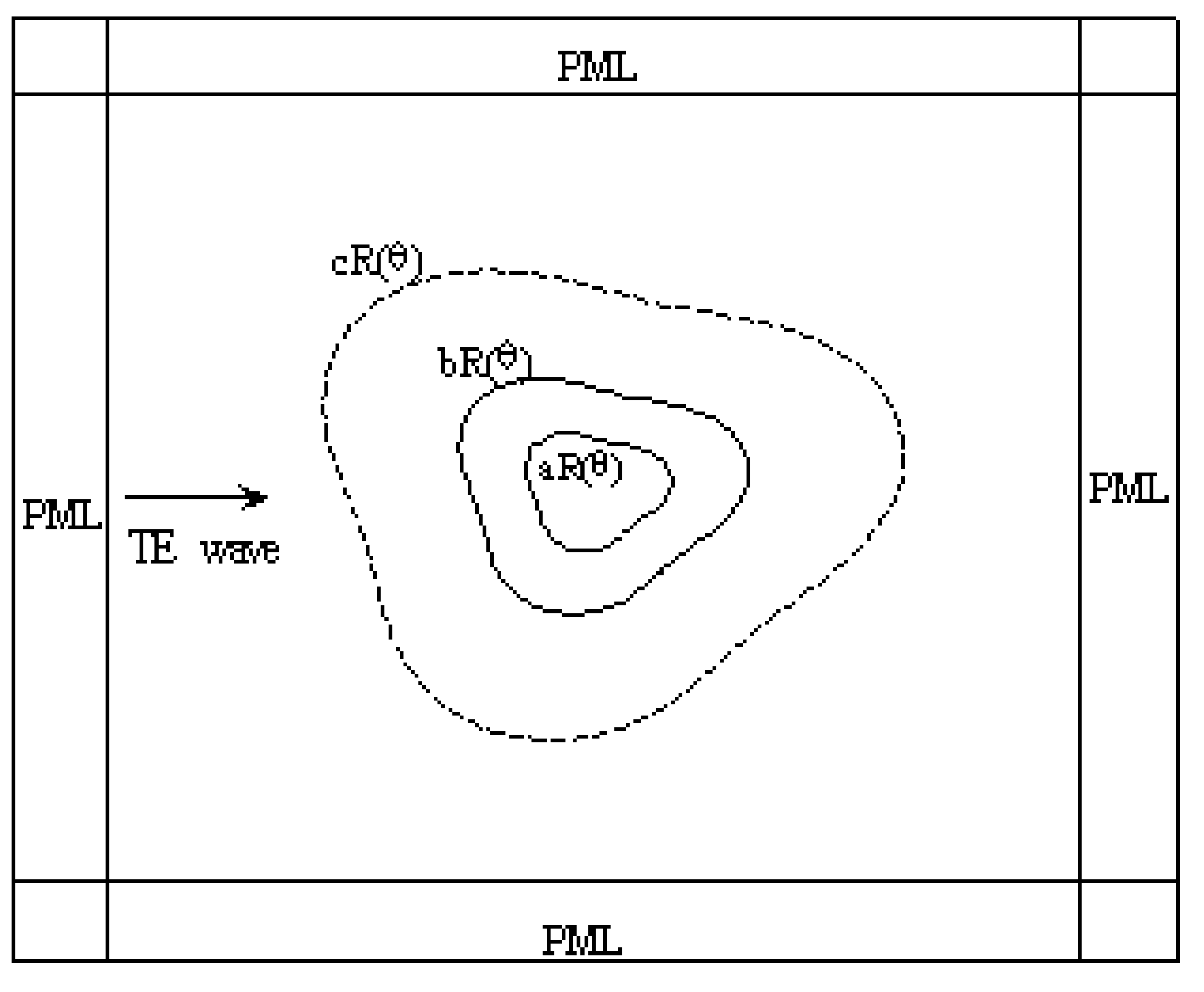
Using transformation optics, the frequency-selective superabsorber with arbitrary geometry can be constructed that consists of an absorbing core coated with a shell of metamaterials. The simulation model is shown in
Figure 1. The contour equations
aR(θ),
bR(θ) and
cR(θ) represent the boundary of the absorbing core materials, outer boundary of the metamaterial shell and the effective virtual boundary. The metamaterial shell serves to amplify the evanescent wave and then induces strong absorption. The key idea behind this design is complementary media [
19]. According to the coordinate transformation theory, when a space is transformed into another space, the permittivity,
ε′, and the permeability,
μ′, in the transformed space, are given by [
20]:
where
ε and
μ are the permittivity and permeability in the original space,
A is the Jacobian transformation matrix, and it denotes the derivative of the transformed coordinates with respect to the original coordinates.
In the region bounded between contours
aR(θ) and
bR(θ), the coordination transformation from the original space to the transformed space is defined as:
Figure 1.
Computational domain of the superabsorber with arbitrary geometry.
Figure 1.
Computational domain of the superabsorber with arbitrary geometry.
In the cartesian coordinate system, it can be written as:
The Jacobi matrix and its determinant can be obtained as:
where:
Substituting Equations (4) and (5) into Equation (1), we can obtain a generalized expression of permittivity and permeability tensors for the 2D superabsorber shown as:
According to Equation (6), to obtain the material parameters for the 2D superabsorber with arbitrary geometries, we just need to change the contour equation
R(θ). For example, when
R(θ) = r0 (
r0 is the radius of a circle), equation (6) gives the permittivity and permeability tensors of the circular superabsorber; when
(r
1 and r
2 are the minor and major semiaxises of the ellipse), we can obtain the material parameters of the elliptical superabsorber. Moreover, the material parameters for the arbitrary N-sided regular polygonal superabsorber can also be obtained by defining the contour equation as:
where
n = 1, 2, 3…,
N, (2
π(
n-1)/
N-π/
N) ≤ θ ≤ 2
π(
n-1)/
N + π/
N),
α =
π/2-
π/
N is the angle between the radius and one side of the regular polygonal,
a0 is the side length of the absorbing core,
θ0 is the rotation angle.
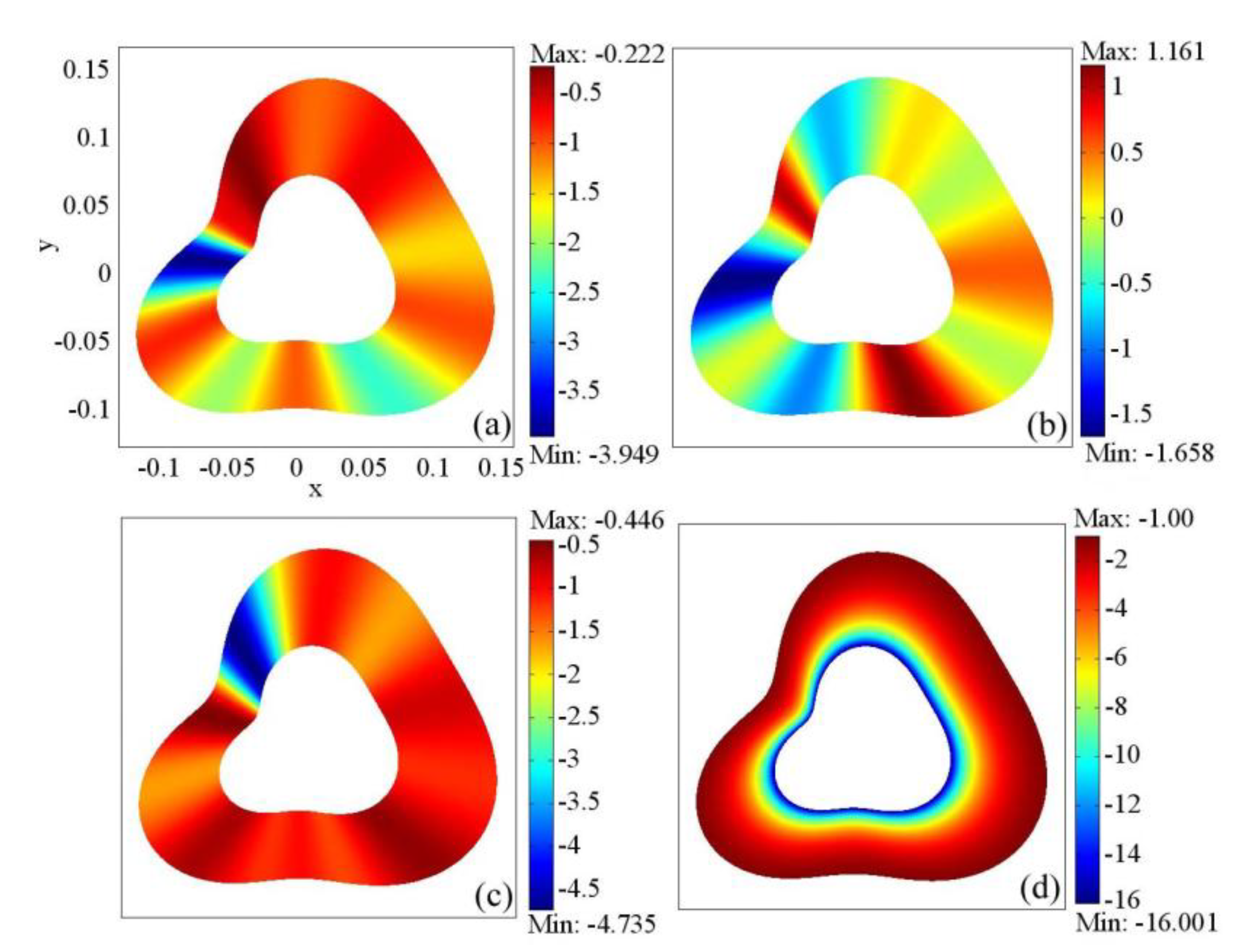
Figure 2 shows the values of the permeability and the permittivity of the metamaterial shell with arbitrary geometry. It is seen that the metamaterial shell is made up of anisotropic and inhomogeneous materials. The distribution of the permeability tensors [
Figure 2a–c] changes with the contour equation of the shell, while the permittivity [
Figure 2d] increases with the radius of the shell. In what follows, we carry out full-wave simulations using the commercial finite element solver COMSOL Multiphysics to demonstrate the functionality of the superabsorberer.
Figure 2.
Permeability and permittivity tensors of the metamaterial shell. (a) μxx. (b) μxy = (μyx ). (c) μyy. (d) εzz.
Figure 2.
Permeability and permittivity tensors of the metamaterial shell. (a) μxx. (b) μxy = (μyx ). (c) μyy. (d) εzz.
3. Simulation Results and Discussion
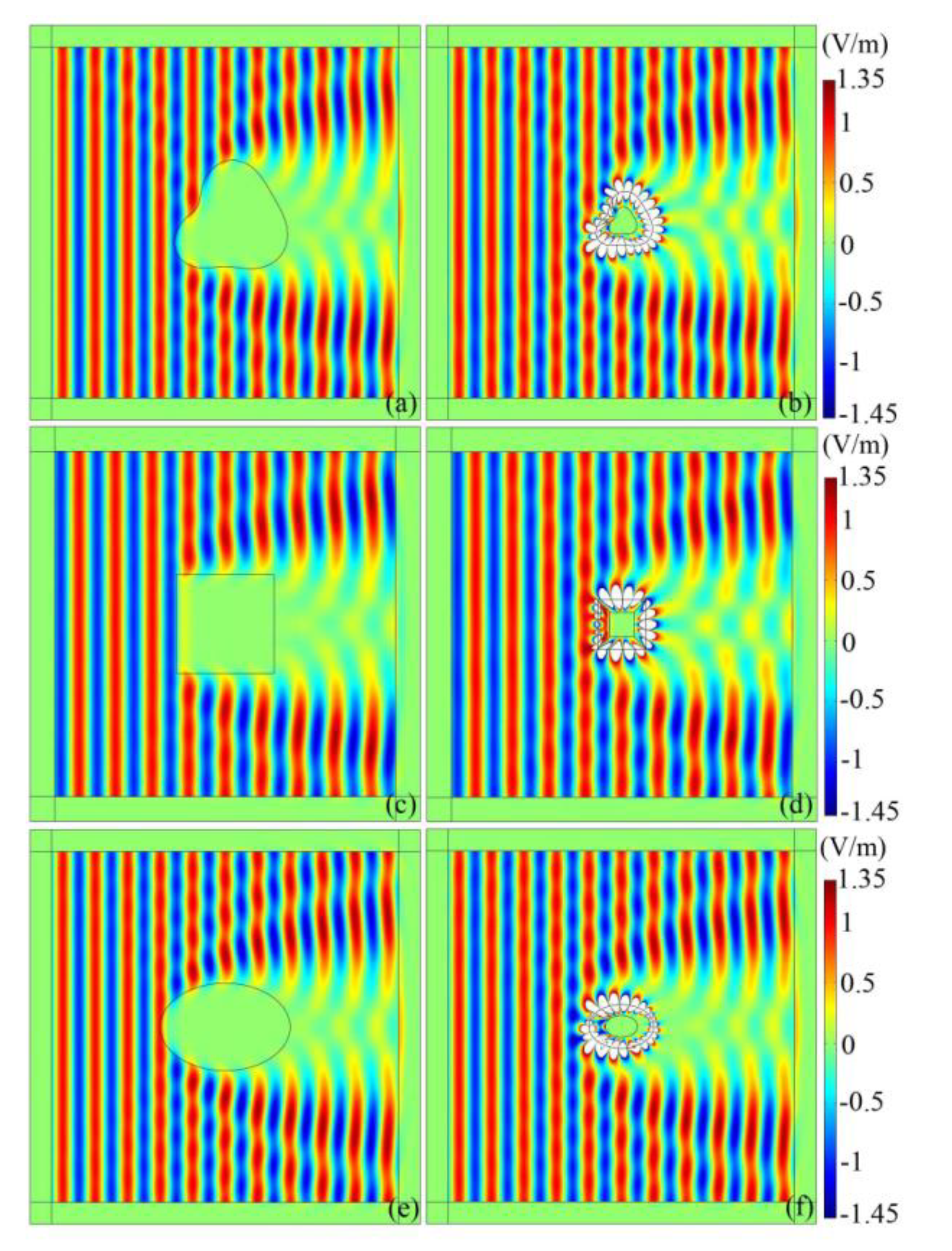
The simulation results of the electromagnetic superabsorber are shown in
Figure 3. The TE plane wave with frequency 2 GHz and unit amplitude is normal incident from left to right. In all the simulation, we choose geometry parameters as
a = 1,
b = 2 and
c =
b2/
a. To show the flexibility of the approach to design the superabsorber with arbitrary geometry, equation (8) is chosen as an example:
Figure 3a shows the electric field distribution in the vicinity of an arbitrary shaped absorbent (
εc =
μc = 1–
i) with contour
cR(θ). It absorbs a large portion of incident plane wave. Such a large absorbent can be replaced by a smaller superabsorber. To illustrate this point, we show in
Figure 3b the case of an absorbing core materials (
εc = –(1–
i)
ε′,
μc = –(1–
i)
μ′) with contour
aR(θ) and coating with a shell of anisotropic and inhomogeneous metamaterials bounded between
aR(θ) and
bR(θ). Comparing
Figure 2a with 2b, it is clear that although the superabsorber is only half the size of the homogeneous absorbing materials, the field patterns in the region of
r >
bR(θ) are almost identical. It indicates that the superabsorber effectively acts as a special device with large absorption cross section. Similarly, the square and the elliptical electromagnetic superabsorbers were simulated as shown in
Figure 3c–f. For the square superabsorber, the side length of the absorbing core materials is set to be a
0 = 0.05 m. For the elliptical superabsorber, the minor and major semiaxises of the absorbing core materials are chosen as r
1 = 0.05 m and r
2 = 0.075 m, respectively. The results for the elliptical superabsorber shown in
Figure 3e and f are in good agreement with those in reference [
15], which further confirm the effectiveness and the generality of the material parameters that we develop.
Figure 3.
Electric field distribution in the vicinity of the absorbing materials (left column) and the superabsorber (right column) under TE plane wave irradiation.
Figure 3.
Electric field distribution in the vicinity of the absorbing materials (left column) and the superabsorber (right column) under TE plane wave irradiation.
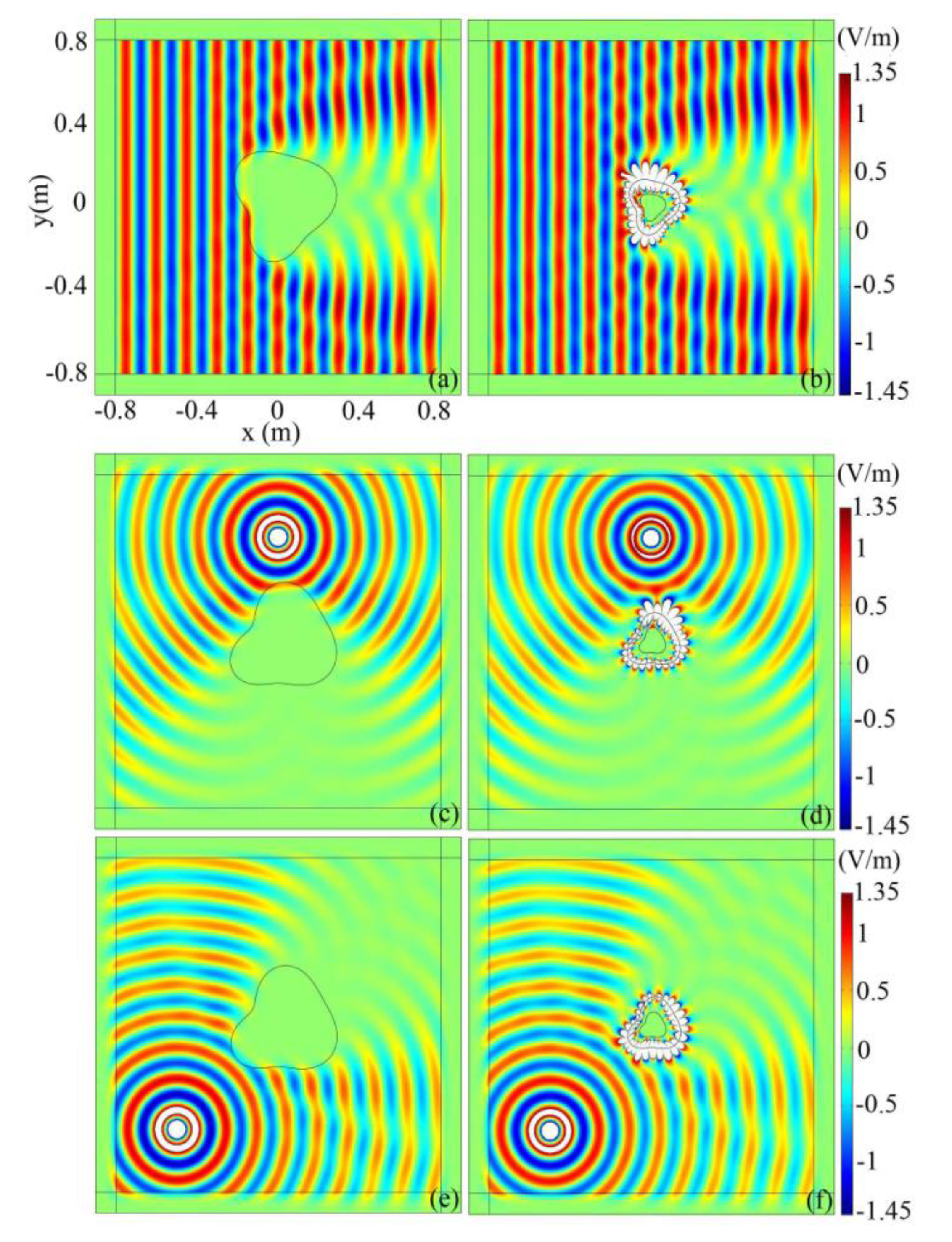
Figure 4a shows the electric field distribution of an arbitrary shaped absorbent which is rotated by
π/4 with respect to the phase fronts of the incoming plane wave.
Figure 4b is the corresponding field induced by the superabsorber. Comparing the two figures, we can find that the patterns of electric field in the region
r >
cR(θ) are almost equivalent, and thus, the superabsorber is valid for arbitrary wave fronts of the incident plane waves. Next, we show the performance of the superabsorber under cylindrical wave irradiation. The line source with current of 10
−3A is located at (0, 0.5 m) and (−0.5 m, −0.5 m) for
Figure 4c–d and e–f, respectively. Apparently, the superabsorbing phenomenon can also be observed, and it is independent on the location of the line source.
Figure 4.
The electric field distribution in the computational domain. (a–b). The TE plane wave is incident from the left and the object is rotated by π/4; (c–d). the line source is located at (0, 0.5 m); (e–f). the line source is located at (−0.5 m, −0.5 m).
Figure 4.
The electric field distribution in the computational domain. (a–b). The TE plane wave is incident from the left and the object is rotated by π/4; (c–d). the line source is located at (0, 0.5 m); (e–f). the line source is located at (−0.5 m, −0.5 m).
From the above simulation, we can clearly observe that the absorption pattern of a large absorbent can be replaced by a small absorbing core coated with a shell of anisotropic negative refractive materials, of which the constitutive parameters are obtained based on the coordinate transformation with Equation (2). Actually, this is not the only way to achieve superabsorption. Now we introduce the other two coordinate transformation equations for building the superabsorber. One is the linear coordinate transformation shown as follows:
It must satisfy the conditions of
r′ >
cR(θ) when
r >
aR(θ), and
r′ >
bR(θ) when
r >
bR(θ), thus, parameters
k1 and
k2 can be obtained as
k1 = (
c–b)/(
a–b),
k2 = (
a–c)
b/(
a–b). Another is a nonlinear transformation with an adjustable factor
m reads:
The permittivity and the permeability tensors can be obtained according to the procedure illustrated in
Section 2, and it is not shown herein for brevity. In what follows, we compare the characteristics of three circular superabsorbers based on linear and nonlinear transformations. The simulation results are shown in
Figure 5.
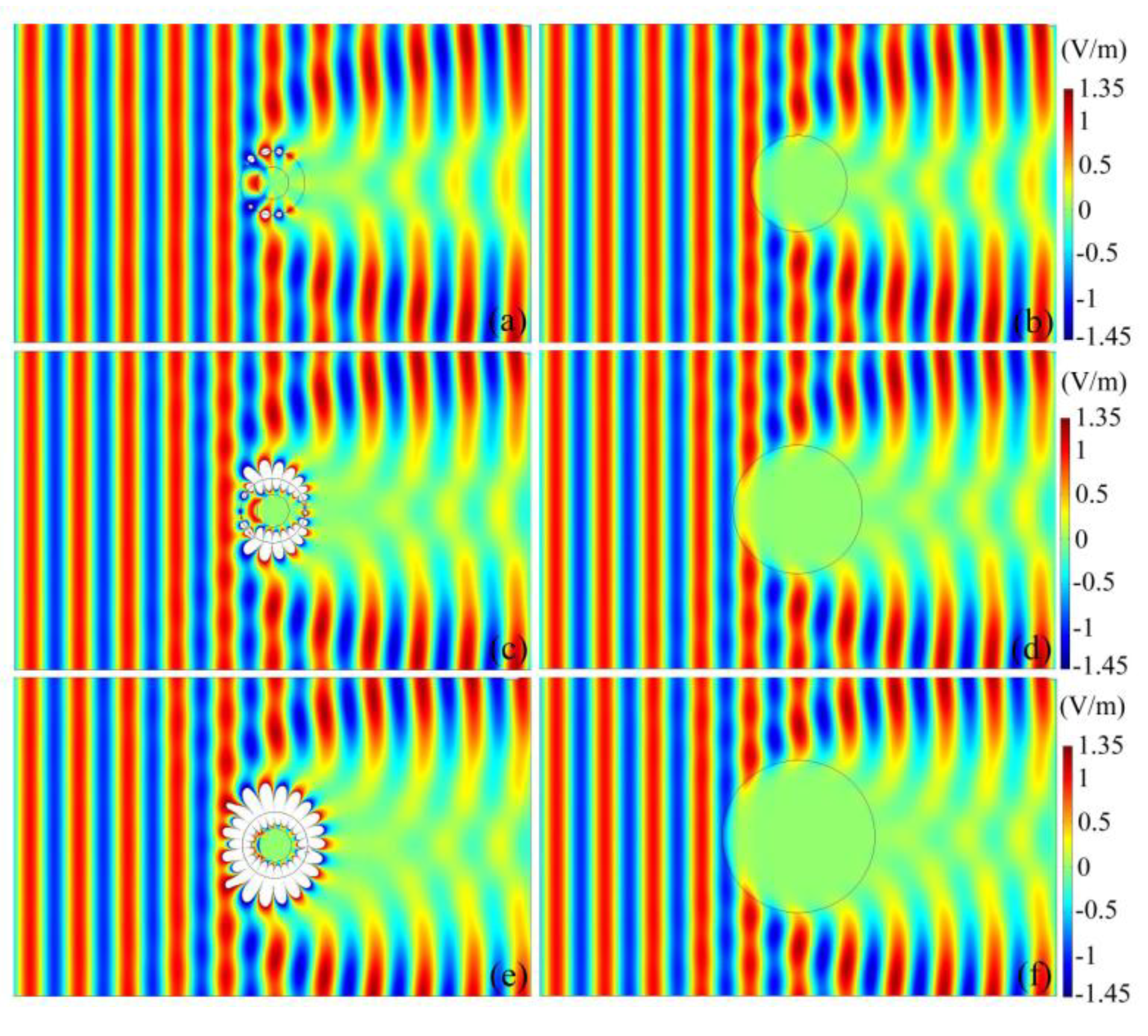
Figure 5.
Comparison of the characteristics of the superabsorber based on linear and nonlinear transformations. a, c and e show the electric field distribution of an absorbing core (εc = –(1–i)ε′, μc = –(1–i)μ′) with radius of r = 0.05 m and coating with a shell of anisotropic negative refractive materials (0.05 m ≤ r ≤ 0.1 m) based on the transformation of Equations (9), (2) and (10), respectively; b, d and f give the electric field distribution in the vicinity of the circular absorbers (εc = μc = 1–i) with radius r0 = 0.15 m, r0 = 0.2 m and r0 = 0.37 m, respectively.
Figure 5a gives the electric field distribution of the superabsorber based on the linear transformation of Equation (9). The radius of the absorbing core materials is
r = 0.05 m. The covering anisotropic negative refractive materials shell is bounded between
r = 0.05 m and
r = 0.1 m. It is seen that the electric field in the region of
r > 0.15 m is equal to the absorber with radius of
r0 = 0.15 m, as shown in
Figure 5b.
Figure 5c displays the electric field distribution of the superabsorber with the same geometry size as that in (a) but based on the nonlinear transformation of Equation (2). Compared with
Figure 5d, it is clear that the field pattern in the region of
r = 0.2 m is equal to the absorber with radius of
r0 = 0.2 m.
Figure 5e shows the simulation result of the superabsorber based on the nonlinear transformation of Equation (10) when
m = 3. It is seen that the electric field distribution in the region of
r > 0.237 m is identical with the absorber with radius of
r0 = 0.237 m, as shown in
Figure 5f. Increasing the value of
m will further enlarge the absorption cross section. From the above simulations, three interesting features can be noticed: First, for the given geometry size, the absorption cross section of the superabsorber based on nonlinear transformation is larger than that based onlinear transformation. Second, theoretically, the absorption cross section can be made arbitrarily large for a specific target frequency by diminishing the size of the absorbing core materials and increasing the size of the metamaterial shell according to Equations (2) and (9). On the other hand, for the given geometry size, the absorption cross section of the superabsorber can be enlarged by adjusting the permittivity and permeability tensors of the metamaterial shell according to Equation (10)
via tuning the adjustable factor
m. Generally, the greater the value of
m, the larger the absorption cross section. It provides a new method for designing the superabsorber. Finally, the white flecks which appear at the outer boundary of the metamaterial shell are caused by the surface mode resonances. It is worth noting that the highest value of the field in the flecks is only 2.45 V/m for the linear transformation, but for the nonlinear transformation based on Equations (2) and (10), the highest value of the field in the flecks reaches 114.38 V/m and 688.88 V/m, respectively. This indicates that the nonlinear transformation will lead to a strong surface mode resonance and a rapid amplification of the evanescent mode, and as a consequence, the absorption cross section is greatly enlarged.


