1. Introduction
Chemical production plants and power generation systems are usually constructed as independent systems. In a typical chemical production plant, heat generated by chemical processes is seldom coupled to other chemical processes requiring energy, resulting in high energy consumption. In the typical power plant, high exergy destruction from combustion processes, which accounts for about 30% of the total fuel exergy [
1], limits the improvement of their thermal efficiency. These defects in energy use can potentially be overcome by polygeneration systems, a promising technology that is attracting increasing attention. A polygeneration system is one that integrates chemical production processes with a power generation system, and produces both chemical and electrical energy simultaneously. To date, a number of polygeneration systems of various configurations have been proposed [
2,
3,
4,
5], and several test projects have been funded for polygeneration plants in the USA and in China [
2,
3]. Most of the researches into polygeneration systems have focused on economic analyses and energy analyses [
6,
7], with a few focused on exergy analyses of polygeneration systems [
8].
Polygeneration systems involve various fields of research, including chemistry, power generation, and even metallurgy. Polygeneration systems designed by chemical experts are inclined to pay too much attention to the chemical conversions being carried out, while polygeneration systems developed by the power generation experts tend to pay too much attention to thermal energy conversion. There is little research that has focused on the actual relationship between the chemical production processes and the power generation systems, or on integration of the polygeneration system based on systemic synthesis, such as comparative analyses of the low conversion and high conversion cases. In fact, decreasing the exergy consumption for the chemical conversion and then utilizing the fuel efficiently for combustion in the power generation system are the key factors that need to be understood in order to enhance the performance of the polygeneration system. The system integration needs to focus on both chemical conversion and thermal exergy conversion synergistically.
Chemical looping combustion (CLC) is a technique where the greenhouse gas CO
2 is inherently separated during combustion. To date, several researchers have investigated CLC [
9,
10,
11], and a project for a novel CO
2 separation system has been conducted by the United States Department of Energy [
12], while Sweden [
13] and Korea [
14] have developed 100 and 50 kW CLC power plants, respectively. The system consists of two reactors: an air reactor and a fuel reactor. Gaseous fuel is introduced into the reduction reactor, where it reacts with an oxygen carrier to produce CO
2 and H
2O. The reduced oxygen carrier is then transported to the air reactor, where it is oxidized back to its original form by air. A recent 1 MW
th chemical looping plant is reported by Ströhle [
15]. A 25 kW
th CDCL (coal direct chemical looping) sub-pilot plant has been constructed and demonstrated successfully at Ohio State University with the support from National Energy Technology Laboratory (NETL) of the United States Department of Energy (USDOE) [
16]. Hamburg University of Technology (Institute of Solids Process Engineering and Particle Technology) had a successful operation of a coupled fluidized bed system for CLC of coal using ilmenite as the oxygen carrier [
17] in Germany. The carbon capture rate based on Australian ilmenite is higher than 96%.
Chemical looping reforming (CLR) produces hydrogen using the CLC principle [
18,
19]. The main reactions in CLR are as follows, with nickel used as Equations (1)–(3):
The first reaction is considered as the primary pathway, whereas the other two reactions are possible reactions. Natural gas is used as fuel in CLR research. To supply enough heat to drive the reforming reaction on the fuel reactor side, part of the natural gas is burned directly to support the reaction.
Another method to produce hydrogen using CLC is water splitting applied to chemical looping (chemical looping hydrogen generation, CLH) [
20]. The CLH process is based on two reactors. The CLH fuel reactor is similar to that used in CLC, but the CLC air reactor in is replaced with a steam reactor, in which steam reacts with the metal to produce hydrogen. In CLH, both sides of the reactions are endothermic. These reactions are as follows, Equations (4) and (5):
Approximately 10% to 20% of natural gas is burned directly to supply the heat for the reactions in SMR (Steam Methane Reforming) and CLH systems.
This paper proposes a polygeneration system integrated with a CLH and coal gasification system. This multifunctional energy system (MES) uses a high quality fuel, natural gas, to improve the utilization of coal, through the chemical looping process. Its purpose is to reveal the mechanism of CLH and coal gasification using exergy-utilization diagram (EUD) methods, to disclose the cascade utilization of chemical energy and physical energy in the system, and to display the performance and CO2 emission reduction of the system.
2. Description and Basic Idea of the Multifunctional Energy System (MES)
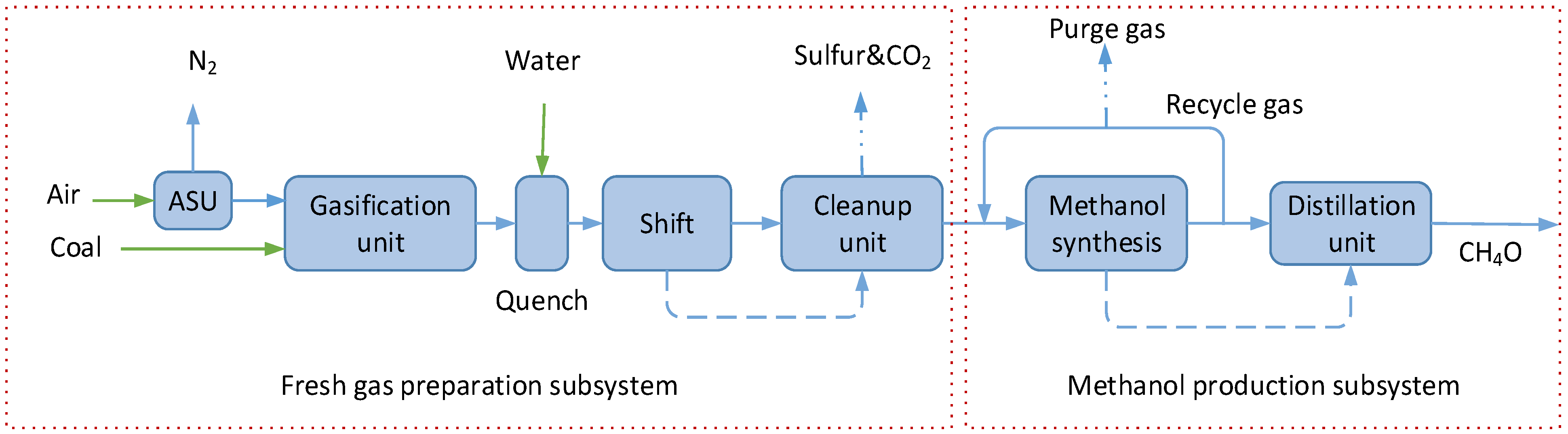
In a coal-based methanol production process, to increase the H2/CO ratio of the syngas to 2.66, which will promise the highest methanol production, the shift reaction is adopted in the fresh gas preparation subsystem. Meanwhile, to reach a high conversion ratio of carbon in coal, the unreacted gas is compressed and recycled to mix with the fresh gas as a recycle stream. However, these measures cause significant exergy consumption, which deteriorates the critical processes in chemical production.
Natural gas, a high quality fuel, is a kind of hydrogen-rich gas, but natural gas is usually burned directly, which accounts for about 30% of the total fuel exergy. Meanwhile, the chemical looping combustion is a new method, which can decrease the exergy destruction of fuel and capture CO2 without energy penalty. The MES use natural gas to adjust the H2/CO ratio to improve the syngas preparation and increase the performance of the system through chemical looping process.
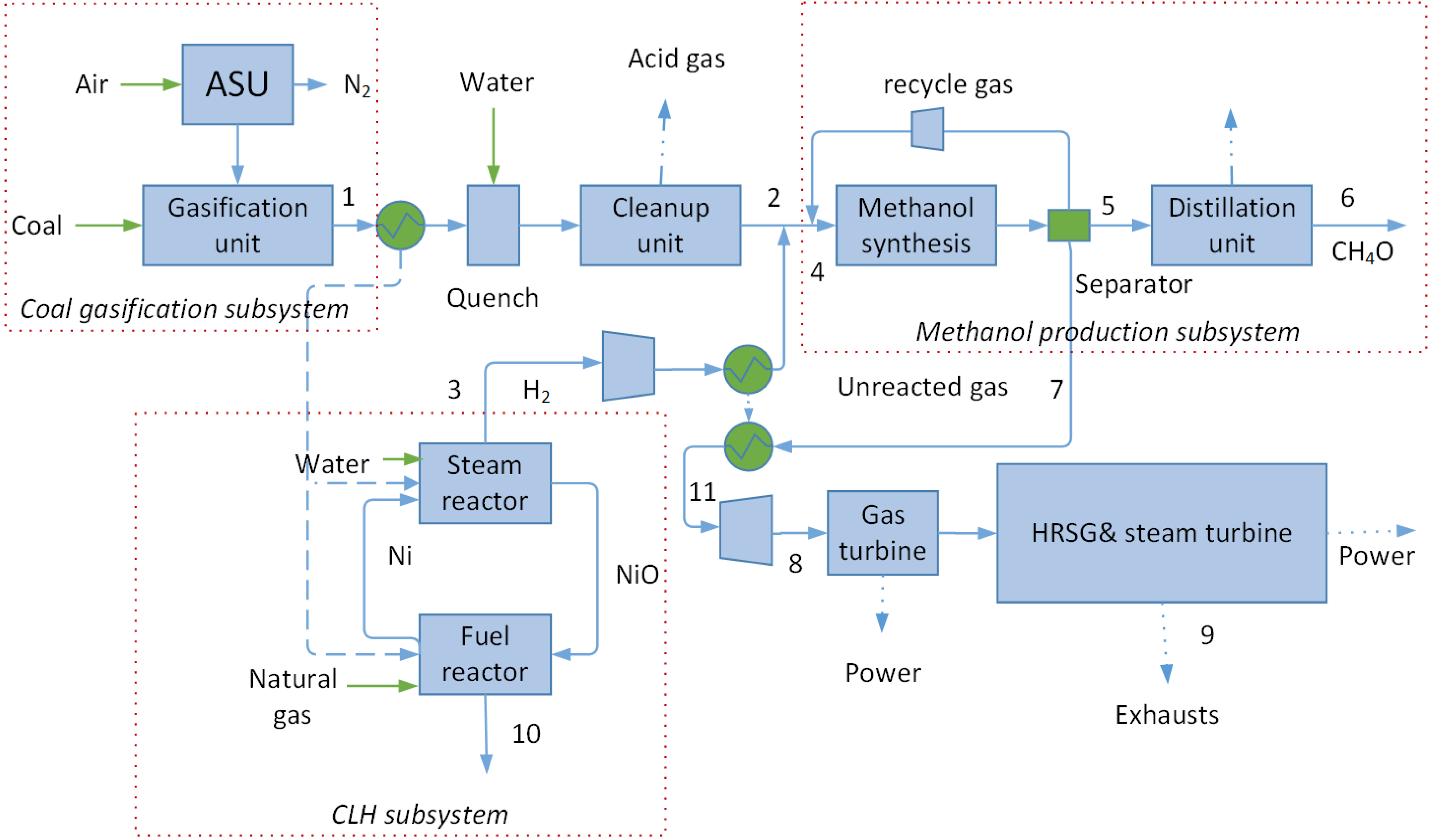
Figure 1 shows a flowchart of the MES system which includes four subsystems: a CLH subsystem, a syngas preparation subsystem, a methanol production subsystem, and a power generation subsystem. In the CLH subsystem, the nature gas is converted into hydrogen, CO
2 and other by-products. One ton of natural gas (about 25 GJ) can be converted into about 0.706 ton of hydrogen. The hydrogen generated in the CLH system is first cleaned up and then is sent to the methanol production system.
In the hydrogen production (CLH) subsystem, the natural gas and the water enter the heat exchanger. In the heat exchanger, the heat donor are the syngas from the gasification unit. Ni is chosen as the oxygen carrier [
21]. The water and the natural gas, preheated from 25 to 1000 °C, act as the heat acceptor. Then, natural gas reacts endothermically with NiO and the catalyst in the reduction reactor. The endothermic reaction path is CH
4 + 4NiO → Ni + CO
2 + 2H
2O and absorbs 253 kJ of thermal energy per mole of CH
4 at 900 °C from the syngas which is produced in the gasification unit. In the steam reactor, the NiO is reduced into Ni in the reduction reactor before it enters the fuel reactor. In the steam reactor, Ni is oxidized with steam and catalyst as follows: Ni + H
2O → NiO + H
2, which is also an endothermic reaction. The reaction absorbs 96 kJ of thermal energy per mole of CH
4 at 900 °C.
Figure 1.
Scheme of the multifunctional energy system (MES).
Figure 1.
Scheme of the multifunctional energy system (MES).
In the syngas preparation subsystem, coal is gasified at 1619 K and 68 bar by steam and oxygen, which is obtained from an air separation unit. For the gasifier, the oxygen consumption is about 0.86 kg oxygen per kg coal, and the ratio of the total lower heating value of cold produced gas to the total lower heating value of coal input is about 76.8%. The gas product leaving the gasifier cyclone enters a cleanup unit for removal of particulates and desulphurization, after being cooled to about 311 K in the product gas cooler. Then the syngas is mixed with clean hydrogen at the ratio of 1.1 by volume. After further cleanup, fresh gas for methanol synthesis can be obtained, which is free of components poisonous to the catalyst, and can then be sent to the methanol production subsystem as feedstock.
The methanol production subsystem is composed of a synthesis unit and a distillation unit. The MES system adopts a partial recycling scheme, recycling part of the unreacted gas back to the reactor. Methanol synthesis is simulated by specifying the temperature approach to real industrial data (the temperature approaching equilibrium was about 38 K [
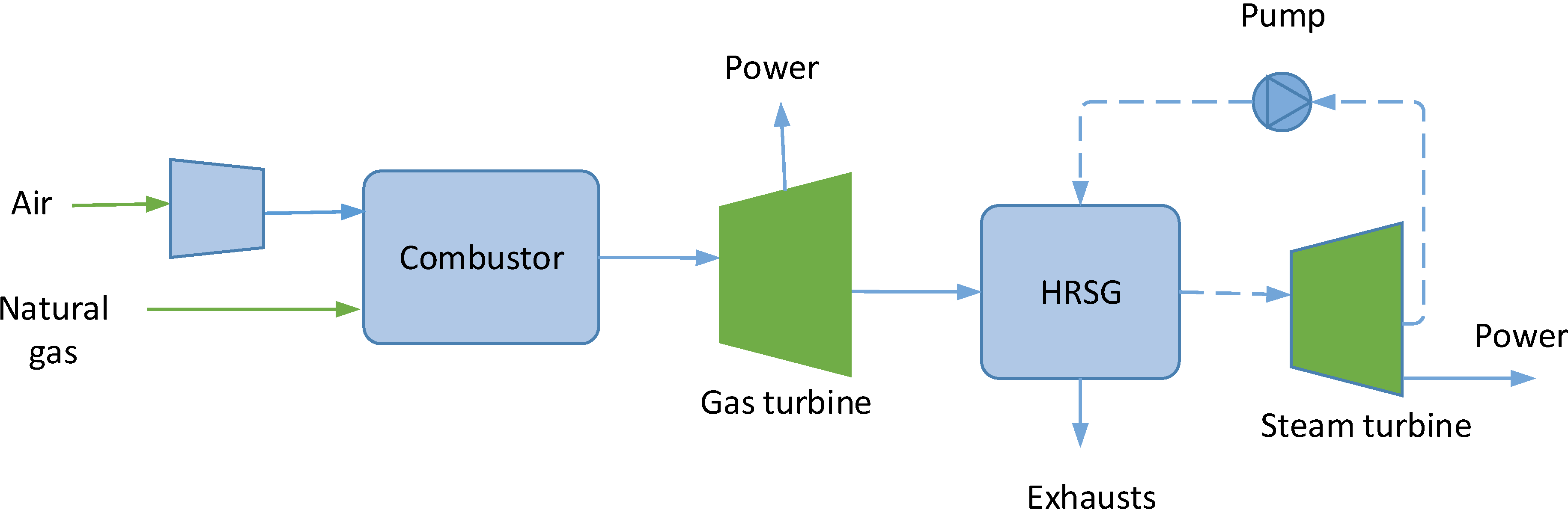
22]). At a pressure of 76 bar, the reactor is maintained at the temperature of 523 K by evaporation of the cooling water. The crude methanol and unreacted gases are separated, after being cooled down to ambient temperature by a cooler, and crude methanol is then sent to a distillation unit. Part of the unreacted gas is cycled back to the reactor, and the other part is sent to the power generation subsystem (combined cycle). The power subsystem supplies the power and the steam that are required in the former processes.
4. Discussion
With the development of complex cycles including complicated chemical/thermal processes, many researchers have paid close attention to the exergy principle for analysis, optimization, and synthesis of the thermal/chemical systems. In order to reveal the internal phenomena of the key processes in the new system, the graphical exergy analysis (EUD methodology), proposed by Ishida [
11], was adopted. The EUD methodology we used here focuses graphically on the energy level difference in a pair of energy donor and energy acceptor. Both the variation of energy level and energy quantity are graphically shown with
A – ∆
H coordinates. Here, the energy level A is a dimensionless criterion (
A = ∆ε/∆
H = 1 –
T0 × ∆
S/∆
H, a ratio of exergy change to energy change), and the energy quantity ∆
H refers to any kind of energy changes, such as thermal energy, power consumption or generation, and energy change in chemical reaction,
etc.The
x-coordinate in the EUD is energy change, and the y-coordinate is energy level A. For an energy-transformation process, there exists an energy donor and an energy acceptor, so the exergy destruction is illustrated by the shaded areas between the curves of the energy donor and energy acceptor. In this way, the EUD methodology has particular advantages over conventional exergy methods in showing: (i) the energy level degradation in each process, instead of only magnitudes of exergy losses obtained from the exergy value difference between the output and input of units; (ii) the variation of driving force by dividing the whole process into infinitive processes; (iii) both global and special information on different phenomena such as work, thermal and chemical processes. Hence, the EUD methodology may provide information on the feasibility of process, driving force, defect points, and potential of improvement from intuitive and global viewpoints [
12].
4.1. Significance of the Chemical Looping Hydrogen Production Process in the MES System
To disclose the role of CLH process in the MES system, we compare the two different ways of using natural gas. In the reference systems, the natural gas is burned directly, which causes a big exergy destruction. The MES system uses chemical looping process to decrease the exergy destruction in the utilization process of natural gas. Instead of shift reaction, the MES system just simply mixed the syngas with hydrogen to reach the CO/H2 ratio. Meanwhile, the energy level of syngas sensible heat is a little higher than the CLH reaction level. The heat is used to drive the fuel reaction and steam reaction in CLH subsystem.
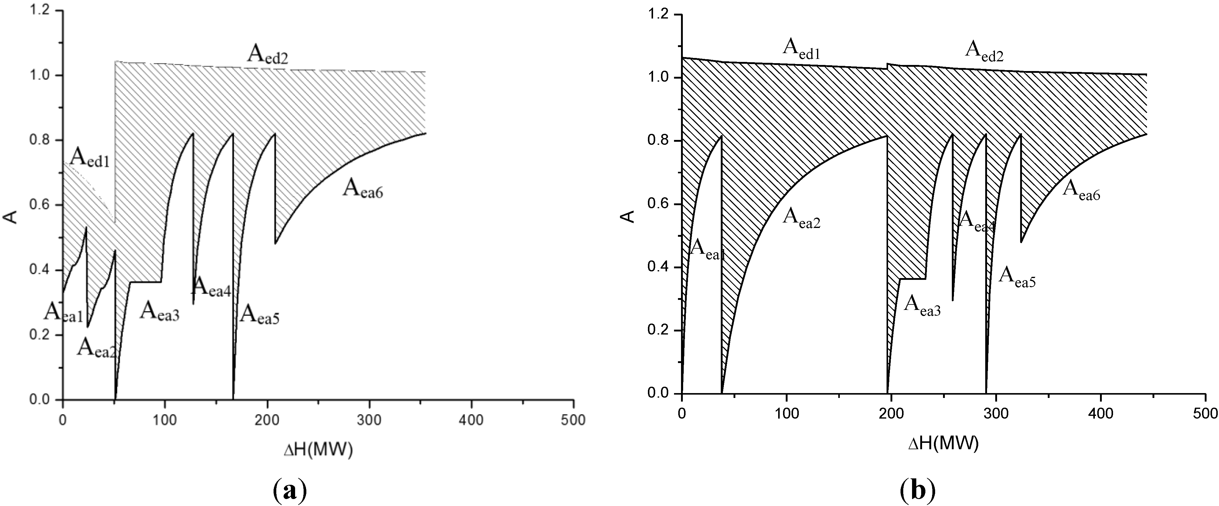
Figure 4a shows the exergy destruction distribution for the combustion of coal in the coal-fired coke oven and the gasification of coal in the gasifier of the MES system. In the CLH subsystem, the syngas acts as the energy donating reaction (curve A
ed1), and the reactions in fuel and steam reactors are the energy accepters (curve A
ea1, A
ea2).
The right part of
Figure 4a shows the exergy destruction of coal gasification process. The coal is the energy donor (curve A
ed2) and the three streams (curve A
ea3, A
ea4 and A
ea5), which act as energy acceptors, are the preheating of water, the preheating of air, and the preheating of coal. The A
ea6 is the reaction level of gasification. The exergy destruction is equivalent to the area between the curves of the energy donor and the energy acceptors, which is 55.9 MW.
Figure 4.
(a) EUD for combustion and gasification in the MES; (b) EUD for combustion and gasification in reference systems.
Figure 4.
(a) EUD for combustion and gasification in the MES; (b) EUD for combustion and gasification in reference systems.
Figure 4b contrasts the combustion of natural gas in the combined cycle and the exergy destruction distributions of the coal gasification in the coal based methanol production system. Curve A
ed1 represents the combustion of natural gas, which acts as an energy donating reaction in the combined cycle, and two streams (curve A
ea1, and A
ea2) act as energy acceptors: the preheating of natural gas and air. The exergy destruction for the combustion of natural gas is 42.7 MW (the shaded area below the curve and of A
ed1 and A
ea1, A
ea2). For the coal gasification process, which is the same as
Figure 4a, shows the exergy destruction in the gasifier is 41.5 MW. Moreover, the thermal energy quantity (Δ
H) between the energy donor and the energy acceptor in the MES (355 MW) was also less than that in the reference systems (444 MW). Therefore the total exergy destruction of combustion and gasification in the reference systems is about 84.2 MW. Comparing
Figure 4a with
Figure 4b, it is clear that the CLH subsystem not only decreases the exergy destruction of natural gas utilization, but also use the sensible heats of syngas reasonably. This is the main reason why the MES system has a much higher performance than reference systems.
4.2. The Elimination of Shift Process and Thermal Integration
There are two different ways to adjust the CO/H2 ratio in the MES and reference systems. In the coal-based methanol production system, the syngas is divided into two streams before the shift unit: one stream about 56%, called “shift gas”, is sent to the shift unit to adjust the CO/H2 ratio to 2.66 via a water–gas shift reaction; and the rest, named “mixed gas”, bypasses the shift unit. The shifted gas combines with the mixed gas after the shift unit. A quenching unit is designed to cool all of the raw syngas leaving the gasifier from about 1619 to 513 K. Before entering the cleanup unit, a heat recovery unit is added to recover the middle temperature heat of the syngas.
From
Table 3, it is clear that the exergy destruction of shift process is 25.6 MW, but the MES decreases this destruction by mixing hydrogen with syngas. Meanwhile, the sensible heat of syngas is used to produce hydrogen as it is. The MES makes the best use of CLH process, and have a high energy saving ratio.
4.3. Advantages for CO2 Capture and Further Considerations
The MES system can effectively use natural gas and coal. In the power subsystem, the conventional steam turbine can be adopted without modification. The gas turbine needs only a slight modification in order to be adapted for purge gas, and this is not a technological obstacle. The liquid phase methanol technology (LPMEOH) that exists today is fit for the methanol synthesis unit in the MES system [
13].
With the same outputs, the fuel inputs of the MES system are about 12.3% less than those of the reference systems, because of the high performance of the MES system. If the CO
2 is not captured, the CO
2 emission ratios of MES and the reference system are 0.177 kg/MJ-output and 0.185 kg/MJ-output. Therefore, the emissions from the MES system would be at least 5% less than those of the reference system. Because of the advantage of CO
2 capture without penalty in chemical looping combustion, the MES can capture 27% of the total CO
2, which can be captured from the stream 10 in
Figure 1. To gain this reduction, the MES system need not add new equipment or increase the energy consumption, because the CO2 is just mixed with steam and it can be separated easily by cooling the steam to liquid. In other words, the MES system is far more environmentally friendly. Based on the CLH system, many different multifunctional energy systems, such as the co-generation of hydrogen, power, and other chemical products (DME) can be constructed with this basic framework, allowing this kind of CLH process to be used as a new method for the efficient utilization of coal.


