Cascaded Position-Flux Controller for an AMB System Operating at Zero Bias


Abstract
: The paper reports on the implementation and the design of a controller for a fuel cell blower (FCB) with active magnetic bearings (AMBs). The cascaded position-flux-centralized controller is comprised of a centralized position control loop and an inner flux control loop. The last one is based on state estimation without explicit flux measurements. As the position control is not dependent on the magnetic field nonlinearities, such a control structure enables operation under a zero bias. The practical working implementation of a flux control for the industrial levitated rotor is shown for the first time. The flux control gives better results than current control for both normal and zero bias operation. The system is analyzed fully, combining rotor dynamics and power amplifier analyses simultaneously. The importance of using the coil voltage in addition to current and practical treatment of the flux control is revealed. The centralized position-flux controller is compared with a state-of-the-art cascaded position-current control, which has inner current control loops. The proposed control solution with a zero bias can achieve a dynamic performance comparable that of a controller with the classical bias current.
1. Introduction
Fuel cell technology provides a clean energy source with high power density. To get a sufficient efficiency, losses in all components of the system should be minimized. Besides efficiency criteria, the technology poses challenges to blower machines that should operate with a high rotational speed to provide sufficient flow and, at the same time, endure high temperatures. In such conditions, traditional bearings cannot withstand high-speed operation without regular maintenance; further, lubrication is not acceptable for an oil-free system.
Active magnetic bearing (AMB) rotor systems are employed in high-speed applications in which other bearing alternatives are not feasible. AMBs, when used to support a high-speed rotor, constitute a coupled multiple-input multiple-output (MIMO), nonlinear, unstable plant with speed-dependent dynamics and disturbances [1].
A typical method to control AMB-rotor systems is to linearize a nonlinear plant around an operating point and applying a linear controller. However, when employing cost-efficient solutions, for example, no-bias operation and small-size actuators, the resulting unstable control plant becomes strongly nonlinear. The linear control design applied to a highly nonlinear system works only in a small neighborhood of the operating point. This limits the position control bandwidth and decreases the operating range with respect to control variables.
The classical AMB control system stabilizes the rotating shaft in five degrees of freedom (5 DOF) using a combination of radial and axial magnetic bearings. For the typical actuator configuration for each DOF, two opposite electromagnets generate attractive forces to the rotor.
Most AMB controllers use a cascaded structure with position and current feedback. In some cases, bearings are used themselves to get the position feedback [2]. The magnetic force is linearized by applying a premagnetization bias current. When applying a flux-based control, the force estimation error is decreased, and the controller can achieve a greater bandwidth than a classical current controller when using accurate measurements [3,4]. However, the flux sensors increase the hardware complexity and the air gap, which reduces the achievable bearing force [5]. At present, the commercially available flux sensors require problematic integration onto the pole surfaces or into the back iron [6,7]. Despite these solutions, flux-feedback is rarely feasible and is not common in industrial implementations.
For improved energy efficiencies, the current control with a reduced bias has been applied. To compensate for the resulting force nonlinearities, such methods, as, for example, inverse-nonlinearity-based compensation [8] and observer-based force linearization, have been proposed [9,10]. In [9], a 1 DOF axial control has been presented with a model-based flux observer for the compensation of eddy currents and other magnetic force nonlinearities. In [10], the force nonlinearity has been incorporated into the outer position observer-based state feedback. A survey of different zero- and reduced-bias control designs for the 1 DOF AMB was presented in [11]. Some discussion on the voltage saturation in a reduced-bias flux-feedback control based on state feedback and observer designs was given in [12]. The effect of the variable bias current on the adaptive AMB control system, with respect to the energy savings and performance, was studied in [13].
This paper presents a flux-controlled zero-biased AMB control system that does not require flux measurements. The proposed cascaded controller is comprised of an optimal centralized outer 4 DOF radial position controller and inner observer-based flux controllers with optimal flux observers. The experimental results, with operation under the zero-bias with flux observer gain scheduling, are shown. In that case, resistive losses of the bearing are significantly reduced compared with the traditional system with the bias current.
Most of the works that are related to AMB systems with flux control demonstrate the mathematical treatment of the problem. These results are supported by numerical examples and simulations, as in [11,12]. Alternatively, the results are validated with a single degree of freedom system as in [3,9]. However, to the best knowledge of the authors, the experiments for a system with a fully supported rotor in a wide range of operation conditions have not been presented in the literature for the flux-based AMB control system.
The practical working implementation of the radial suspension using the flux control (without flux measurement and with centralized outer control) for an industrial levitated rotor is shown for the first time. The flux control gives better results than the current control for both normal and zero bias operation. This approach helps to deal with nonlinearities enabling the use of zero bias or variable bias without the necessity of control adaptation (e.g., as required for stability in [12]), because the position control does not depend on flux bias. The power amplifier is combined with the actuator and rotor model to make consistent, full analyses of the system. The importance of using the coil voltage, in addition to the current and the practical treatment of the flux control, is demonstrated.
2. Control Platform and Plant Modeling
The most commonly used AMB rotor system comprises two eight-pole radial actuators, a motor, and a separate thrust AMB. For modeling and control synthesis, we consider the radial suspension that is decoupled from the axial AMB forces.
2.1. Control System Overview
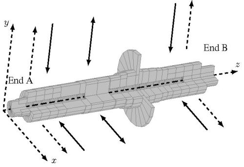
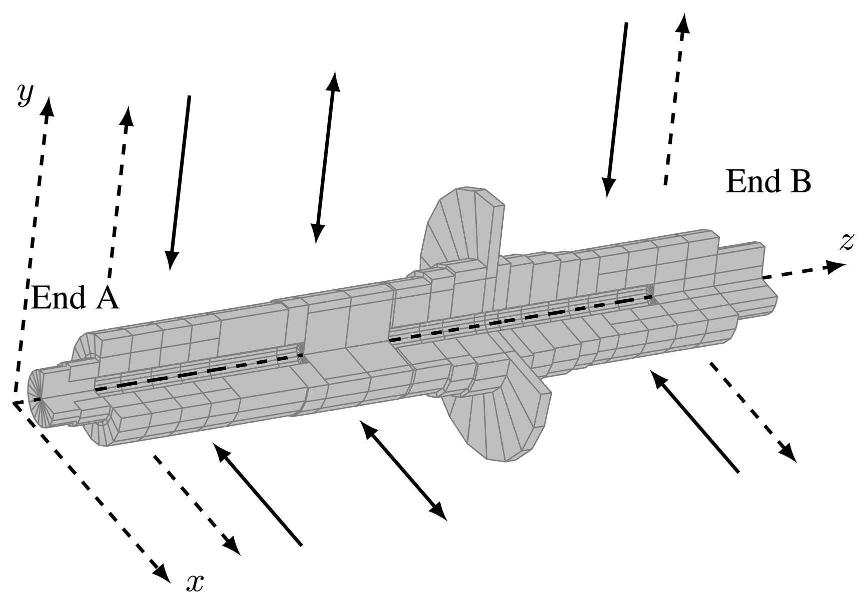
The case study AMB rotor system has a horizontal rotor (Figure 1), two radial AMBs, one axial AMB, and a permanent magnet (PM) synchronous motor. The selected parameters of the AMB system are: stiffness of the PM of the motor kx,PM = 21 N/mm; rotor mass m = 2.5 kg, rotor length 262 mm; nominal magnetic air gap length l0 = 0.58 mm; clearance to the safety bearings from the geometric center 0.25 mm; average nominal inductance of the radial AMBs at the nominal air gap L = 2 mH; effective number of turns in each electromagnet N = 108; bias current for current control i0 = 2.5 A; and the maximum current imax = 6 A. The AMB control system is implemented on a dSPACE DS1005-09 platform using a CMSS 65 Eddy Current Probe System compriseing three single-channel sensors installed on each of two measuring planes at the ends of the rotor. The AMB coils are driven by servo amplifiers in a half-bridge configuration. The amplifiers operate with a supply DC link voltage udc = 60 V, which is the maximum voltage applied to the coils, and a switching frequency of 40 kHz. The sampling time is Ts = 100 μs.
2.2. Approximating the Mechanical Rotor Model
The rotor (Figure 1) is modeled using a custom finite element method (FEM) code [14] that outputs the rotor model matrices to MATLAB. For the case study subcritical system, we retain three flexible bending modes calculated for a free-free rotor in each plane (in the xz and yz planes) for control verification. The two modeled lowest natural frequencies are about 2 kHz and 6 kHz. The equation of motion for the rotor spinning with the angular speed, Ω, in the modal coordinates is:
The matrices of the mechanical system description, Mm, Km, Gm and Dm, are the diagonal mass matrix, the diagonal stiffness matrix, the skew-symmetric gyroscopic matrix, and the damping matrix, respectively. fm and ηm are the vector of the modal forces acting on the rotor and the vector of modal coordinates. The first four coordinates correspond to the rigid rotor modes in the center of gravity coordinates.
In order to include the bearing stiffness matrices, Ki and Kx, in the rotor model, a transformation (matrix), Cf, from the position of the actuators to the center of mass is applied. Further, to be able to provide the rotor displacements in the position of the sensors and the bearings and the velocities at the location of the bearings, transformation matrices Cs and Cb are required. Additionally, the equivalent transformation matrices are necessary to include the stiffness of the PM in the rotor model [15].
2.3. Current-Controlled AMB
The analytical approximation of the magnetic force of a single electromagnet, f1, and of a pair of opposite electromagnets, f, can be expressed as a function of the bearing currents, i1, i2, and the rotor displacement, x, from the center point:
The nominal values of the dynamic inductance, Ldyn, and the velocity-induced voltage coefficient, ku, are calculated by using the flux density in the air gap, B, which has been obtained from Ampère's circuital law, in the operating point x = 0 and neglecting the magnetization of the iron:
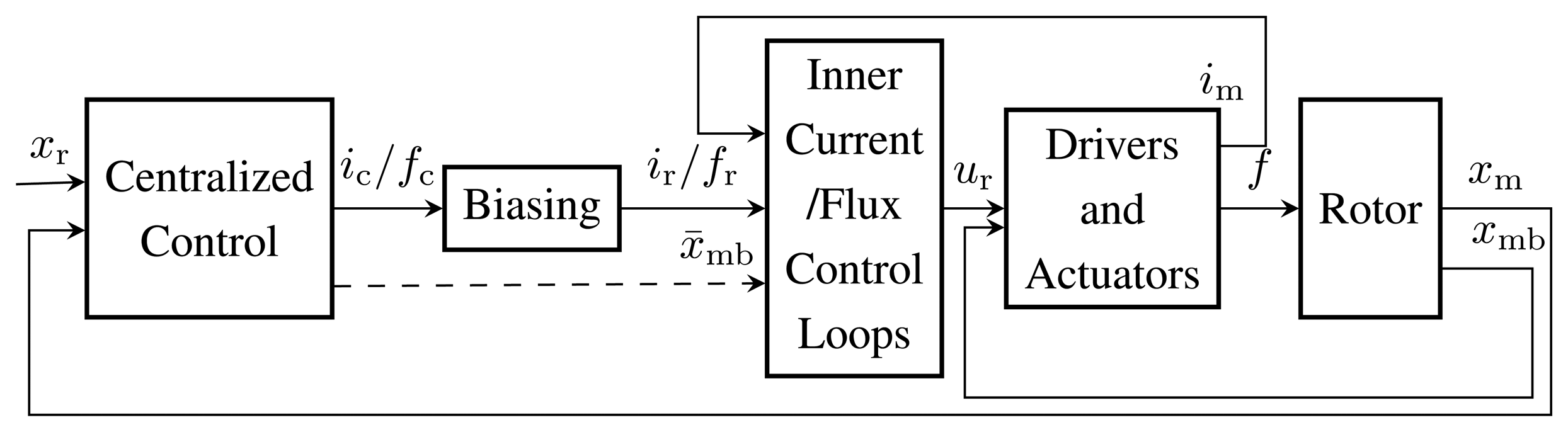
In a typical state-of-the-art inner current-voltage controller with a bias linearization and a differential driving mode, the reference voltage command provided to the driver is ur = Kc(ir − im), where the reference current ir = i0 ± ic (Figure 2). Neglecting the coil resistance, assuming no voltage saturation and no pulse width modulation (PWM) or measurement delays, and assuming nominal inductance, the closed inner-loop current control dynamics, Gcl,i, can be approximated in the s-domain by
The system will be working without magnetic saturation if the maximum current value:
The case study system has been designed assuming a relatively safe value for the saturation flux density, Bsat = 0.8 T. Using Equations (6) and (8), we select the proportironalll gain that rresults in a conservative current control loop bandwidth of 880 Hz. This conservative selection ensures that the first-order approximation (5) holds and no nonlinear effects related to the voltage saturation are present. In such a case, the inner loop acts as a low pass filter applied at the output of the outer position controller, which cuts off the high frequency content.
2.4. Flux-Controlled AMB
As an alternative to the current control in the inner loop, the flux control can be applied. However, instead of using the flux measurement [16], we apply the estimated flux from the measured currents [9].
The magnetic force of a single electromagnet and of a pair of oeppaosite electromagnets can be expressed by using the flux, Φ, instead of the current and air gap, as:
The magnetic force computation is now not dependent on the rotor position, as in Equation (2). Now, it is straightforward to use the outer position controller, which provides the reference force signal, fr, to the inner flux controllers (Figure 2). The reference force is constructed from the bias force, f0, and the control force signal, fc, such as fr = f0 ± fc. The reference force can be changed to the reference flux:
The proportional current feedback is replaced with the flux feedback control ur = KΦ(Φr − Φm), where the measured flux, Φm, can be replaced by the estimated value, Φes. The feedback gain, KΦ, replaces the current feedback gain, Kc. Neglecting the coil resistance and assuming no saturation and no PWM or measurement delays, the closed inner-loop flux control dynamics, Gcl,Φ, can be approximated in the s-domain by:
Analogically to the current control, we obtain the maximum bandwidth of the inner flux control (approximated as a first-order system) with respect to the flux rise time from 10% to 90% of the maximum flux value when using the maximum voltage, udc:
Equation (12) results in a bandwidth that is approximately equal to 1900 Hz for the design value of the saturation magnetic flux density. However, with the inner flux loop, the major concerns are the maximum allowable current in the windings and the resulting saturation of the force control signal. The effects of the magnetic saturation can be taken into account in the flux observer. When rewriting (12) in terms of the maximum allowable current and the nominal inductance, we obtain the same maximum bandwidth estimate as for the inner current control loop:
For this comparison, the inner-loop controller bandwidth is selected to have the same bandwidth as the current-controlled method ωbw = 880 Hz.
When not measured, the fluxes can be calculated by integrating the applied voltages, u, in the electromagnets:
2.5. Outer Position Control for Current-Controlled AMB
For the classical AMB controller, the force (2) is linearized about the operating point (ic = 0 and x = 0) for two opposite coupled horseshoe electromagnets:
The current stiffness, ki, and the position stiffness, kx, are embedded in the FEM-based mechanical rotor model in the bearing stiffness matrices, Ki and Kx. For the coupled electromagnets:
For the selected operational point, the radial current stiffness ki = 16 N/A and the radial position stiffness kx = 71 N/mm. The dynamics of the current control loop, the PWM delay and the position sensors are approximated as transfer functions and added to the complete linear plant model that is used for the iterative centralized controller synthesis and verification [17].
The open-loop transfer function of the complete plant in the Laplace domain using the state variable form can be written as
G(s) is a transfer function matrix of the plant. u and y are the vectors of the control currents and the measured displacements, respectively. A, B and C are the state matrix, the input matrix, and the output matrix in the state-space representation, respectively.
In general, controllers that apply the actuator model based on currents show degraded performance when moving away from the operating point (and improved performance in the operating point). For current-controlled bearings, the plant, as seen by the outer control loop, includes a destabilizing negative stiffness that couples the rotor position and the electromagnetic dynamics of the actuator. Table 1 shows the eigenvalues of the open-loop system models. Each AMB rotor system comprises rigid body rotor (eight poles, including two double pole pairs) and the first-order actuator approximations (four poles). In the current-controlled AMBs, the bearing stiffness influences the negative part of the eigenvalues related to the rigid rotor. The eigenvalues of the rigid rotor move away from the origin when the bearing stiffness is increased. When including the stiffness of the permanent magnet of the case study rotor, the eigenvalues move evenly, further from the imaginary axis. The eigenvalues appearing far to the left from the imaginary axis are related to the actuator model (four poles).
The linearity of magnetic force increases for high bias currents. However, the high bias results in increased losses, a high bearing stiffness, and increased noise in position measurements, because of the high stiffness and current signal levels. To compensate for the influence of the rotor position and the bearing current on the inner-loop controllers and to keep their dynamics more linear, a variable feedback gain, Kc(x, i), could be considered [8]. The static force field nonlinearity as a function of currents and position can also be compensated for, for example, by using an inverse nonlinearity method [8], a nonlinear force model in the observer [10], or an extended Kalman filter (EKF) [18]. However, the compensated control systems, as in [8,10], are sensitive to modeling errors, and they are difficult to implement without an accurate identification of the nonlinear plant models. The inverse nonlinearity compensation assumes that there are no actuator dynamics between the compensated control and the actual control signal and no limitation on how fast the control signal can be produced. Again, the EKF, when applied to the centralized plant model comprising actuators and rotor dynamics, poses a significant computational burden and accurate modeling challenges when implemented in real time [18].
2.6. Outer Position Control for the Flux-Controlled AMB without the Flux Measurement
For the flux-controlled AMB, the outer position controller is synthesized based on the plant model without the actuator dynamics (1) and without the bearing stiffness matrices, but with the PM stiffness. As presented in Table 1, the open-loop system model changes from marginally stable to unstable when including the PM stiffness. It was possible to achieve the relatively high bandwidth of the outer position control in the fluxed-controlled AMB rotor system (250 Hz) compared with the achievable bandwidth of the outer position controller in the current-controlled AMB rotor system (50 Hz). This results from the different nominal plant models for both control structures and could be dependent on the application.
The air gap in the actuator location of the electromagnet, l, from Equation (15), applied to each inner control loop has to be estimated by the observer in the centralized outer control loop, because of the non-collocated system. The observer comprises the full-order state estimator and constant disturbance estimator. Selecting the higher outer control loop bandwidth improves the low-frequency disturbance rejection, the speed of the position estimation and, consequently, the flux estimation in the inner control loops.
2.7. Zero Bias Operation and Its Drawbacks
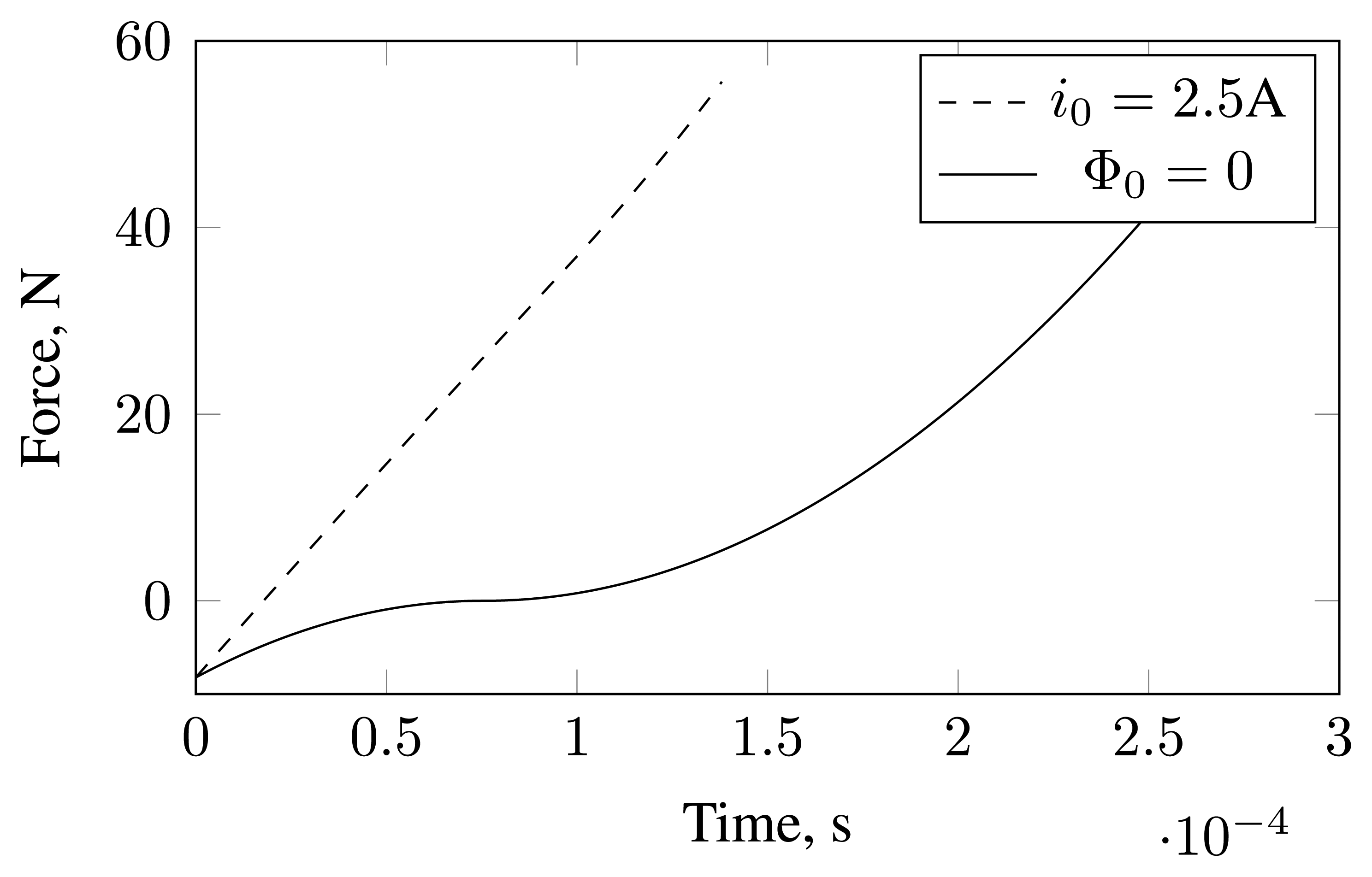
Using Equations (9) and (14), the force slew rate available for the pair of the opposite electromagnets is:
For zero magnetization or bias fluxes, the force slew rate is zero, and it grows with the growing bias. In practical machines, there are always some load forces, and even for the assumed zero-bias operation, the force slew rate is positive. In the studied machine, which is oriented horizontally, there is a gravity force load to overcome by four out of eight radial electromagnets. Therefore, in the zero-bias operation:
3. Comparison of Current- and Flux-Controlled AMB Systems
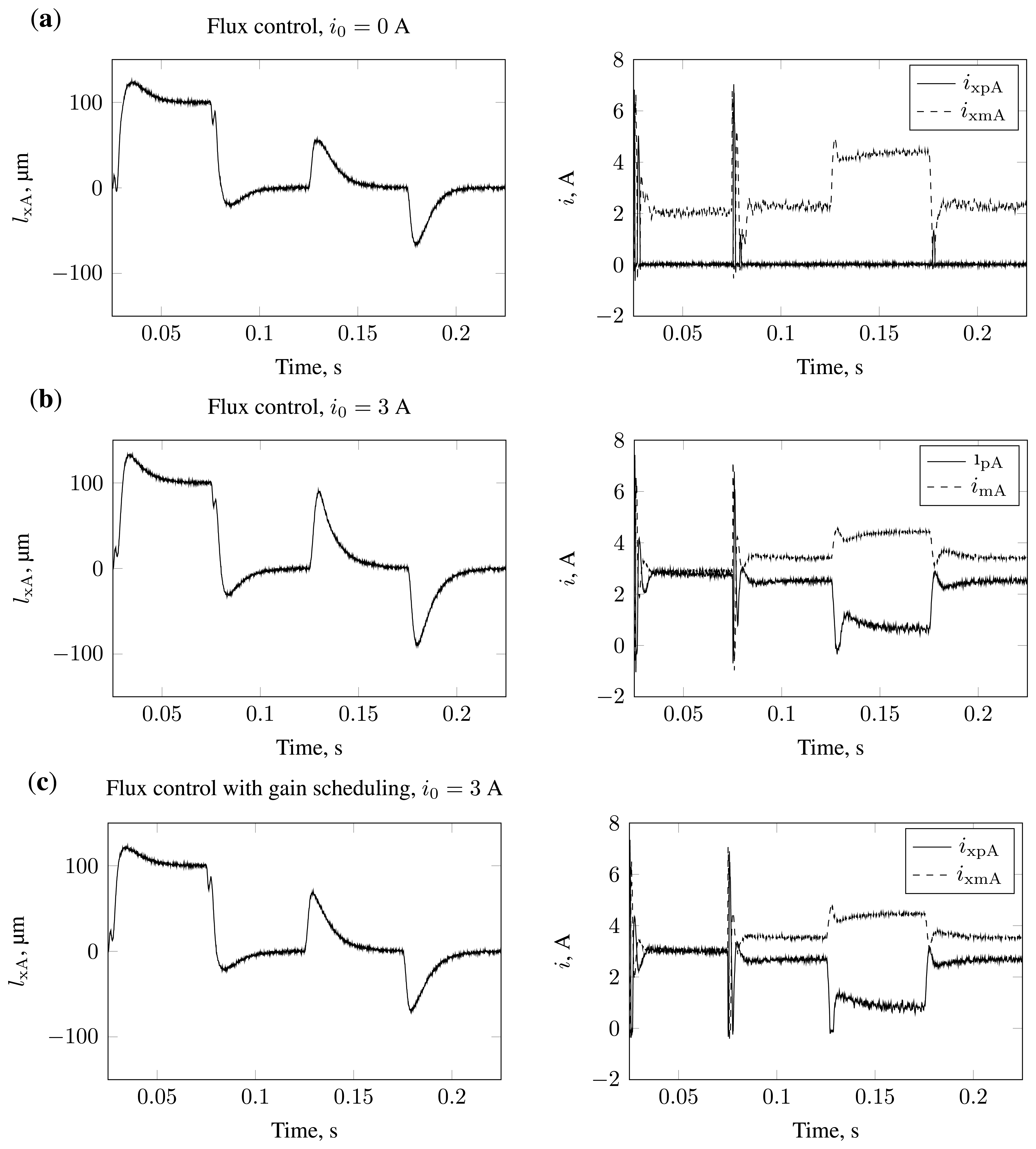
For testing the flux-based zero-bias control, a Linear-quadratic-Gaussian (LQG) outer position controller is synthesized [8,17]. The weighting matrices for both centralized LQG (flux and current) controllers have been optimized to achieve maximum bandwidth and minimum sensitivity peaks. The stability is verified by testing for the location of the closed-loop poles when using a full plant model that comprises the flexible rotor pmeeondraenl, the PWM delay, the sensor delay and the first-order actuatoar, approximation. In the simulations, the controller is tested against the full plant model, which additionally comprises the Gaussian noise in the measured currents and positions, the gravity vector, and the nonlinear actuator with magnetic saturation and limited DC-link voltage. Figure 4(a) and 4(b) show the simulated step reference and step disturbance responses (in the x-direction at the A-end of the rotor) of the closed-loop system operating with flux inner control with zero and non-zero bias. The actuator dynamics are dependent, among others, on the coil current and, therefore, the responses of the same control, but at the bias, fluxes equivalent to 0 A and 3 A differ. In order to improve the estimation in the inner flux controllers, an estimator gain scheduling is applied. The estimator feedback gain is computed for linearized dynamics for different air gaps. The observer pole is placed so that its natural frequency equals twice the bandwidth resulting from Equation (13) for position-dependent inductance. A more accurate and faster flux estimation improves the step responses of the overall cascaded controller (Figure 4(c)).
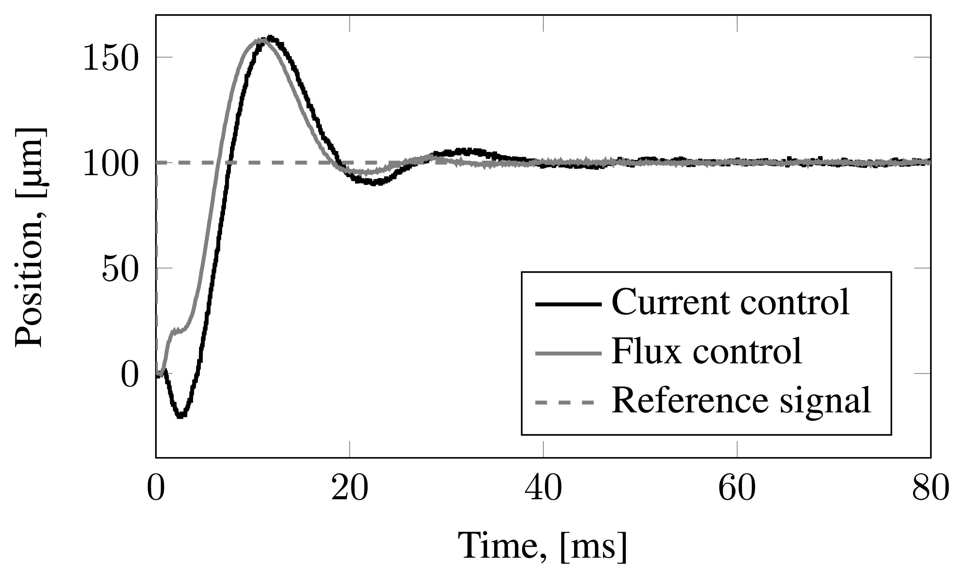
The discussed current- and flux-controlled AMB operation is demonstrated experimentally. The experiment set-up and devices used for the measurements are explained in [15]. The current control operates with i0 = 2.5 A, while the flux control operates with zero bias. The initial lift-up is presented in Figure 5. The responses from the A-end have a higher overshoot compared with the responses from the B-end. The A-end is closer to the PM motor. Figure 6 presents the step responses for a standstill operation. The undershoot in the response of the current-controlled AMB-rotor system could indicate that the system has unmodeled dynamics with an open right-half plane zero. The undershoot is not observed in the simulations; further, the unstable zeros are not observed in both modeled closed loop systems. The undershoot increases the settling time of the current controller.
The measured output sensitivity function accesses the AMB system stability [19]. The measured output sensitivities of system at standstill and at 11, 000 rpm are presented in Figures 7 and 8. The excitation signals have been injected to the system as position measurement noise, and the resulting rotor positions plus the injected noise signals have been measured. The bias current- and zero-bias flux-controlled cases face the same system modeling errors, noise, and hardware limitations. However, the closed-loop system with flux-controlled actuators provides lower sensitivity peaks, a higher bandwidth, and a shorter settling time than the centralized controller based on the current-controlled actuators.
4. Conclusions
The experimental results show that the use of the linear centralized position control in the outer control loop of the flux-controlled AMB rotor system is feasible by using flux observers in the inner control loops instead of flux measurements without explicit identification of the plant's parameters. The tested cascaded control with the flux-controlled AMB not only shows better robustness to modeling errors and higher bandwidth compared with the current-controlled system, but also without changing the outer controller, it enables operation at a zero bias and within magnetic saturation. Because of the zero bias, the static losses are reduced.
The linear outer-loop controller has a reduced number of states as a result of omitting the states corresponding to the inner control dynamics when compared with the classical current-controlled AMB controller. However, the implementation of the inner loop flux observers is considerably more complex than the basic feedback in the current-controlled AMBs.
The flux-controlled AMBs show less oscillations and a smaller overshoot during step response and the initial lift-up, as well as lower sensitivity peaks. The experimental step responses and the measured sensitivity peaks differ from the simulations and analytical results. The experimental responses could be improved when using a plant model with the identified parameters and not the design parameters for the synthesis of controllers. Future studies will focus on the development of the adaptive inner and outer controllers for variable bias operation, as well as system identification.


| Tested plant model | Real value (s−1) | Imaginary value (s−1) |
|---|---|---|
| Current-controlled AMB | ±242.5 | 0 |
| ±312.3 | 0 | |
| ±5493 | 0 | |
| Current-controlled AMB with PM | ±256.4 | 0 |
| ±318.9 | 0 | |
| ±5493 | 0 | |
| Flux-controlled AMB | 0 | 0 |
| Flux-controlled AMB with PM | ±22.28 | 0 |
| ±102.9 | 0 | |
Acknowledgments
The authors would like to thank the Finnish Funding Agency for Technology and Innovation (TEKES) for their financial support to the project “SaLUT-FCB to Business”, Janne Nerg and Jussi Sopanen and other research team members of Lappeenranta University of Technology (LUT) and Saimaa University of Applied Sciences (SAIMIA) for invaluable contributions toward the development of the case study prototype. The work has also been supported by Academy of Finland No. 270012 and No. 273489, and partially supported with Statutory Work of Department of Automatic Control and Robotics, Faculty of Mechanical Engineering, Bialystok University of Technology, No. S/WM/1/2012.
Conflicts of Interest
The authors declare no conflicts of interest.
References
- Schweitzer, G.; Maslen, E.H. Magnetic Bearings Theory, Design, and Application to Rotating Machinery; Springer Berlin, Heidelberg: Berlin/Heidelberg, Germany, 2009. [Google Scholar]
- Niemann, A.C.; van Schoor, G.; du Rand, C.P. A self-sensing active magnetic bearing based on a direct current measurement approach. Sensors 2013, 13, 12149–12165. [Google Scholar]
- Bahr, F.; Melzer, M.; Karnaushenko, D.; Makarov, D.; Karnaushenko, D.; Mönch, J.I.; Malane, D.; Schmidt, O.G.; Hofmann, W. Flux Based Control of AMBs Using Integrated Ultra-Thin Flexible Bismuth Hall Sensors. Proceedings of the 13th International Symposium on Magnetic Bearings (ISMB13), Arlington, VA, USA, 6–9 August 2012; pp. 1–15.
- Mohamed, A.M.; Emad, F.P. Nonlinear Oscillations in Magnetic Bearing Systems. IEEE Trans. Autom. Control 1993, 38, 1242–1245. [Google Scholar]
- Gahler, C. Dynamic Testing and Control with Active Magnetic Bearings. In Ph.D. Thesis; ETH No. 12718; ETH Zürich, Zürich: Switzerlands, 1998. [Google Scholar]
- Kipp, R.W.; Ilach, J. Magnetic Bearing Including a Sensor for Sensing Flux in the Magnetic Flux Path. U.S. Patent 6057681, 2 May 2000.
- Kjolhede, K.; Santos, I.F. Experimental Contribution to High-Precision Characterization of Magnetic Forces in Active Magnetic Bearings. J. Eng. Gas Turbines Power 2007, 129, 503–510. [Google Scholar]
- Jastrzebski, R.P.; Pöllänen, R. Compensation of nonlinearities in active magnetic bearings with variable force bias for zero- and reduced-bias operation. Mechatronics 2009, 19, 629–638. [Google Scholar]
- Zingerli, C.M.; Kolar, J.W. Novel Observer Based Force Control for Active Magnetic Bearings. Proceedings of the 9th International Power & Energy Conference (IPEC 2010), Singapore, 27–29 October 2010; pp. 2189–2196.
- Jastrzebski, R.P.; Pyrhonen, O. Model-based centralized AMB control with position and current feedback and nonlinear observer. Przeglad Electrotechn. Electr. Rev. 2012, 88, 253–256. [Google Scholar]
- Tsiotras, P.; Member, S.; Wilson, B.C. Zero- and Low-Bias Control Designs for Active Magnetic Bearings. IEEE Trans. Control Syst. Technol. 2003, 11, 889–904. [Google Scholar]
- Tsiotras, P.; Arcak, M. Low-bias control of AMB subject to voltage saturation: State-feedback and observer designs. IEEE Trans. Control Syst. Technol. 2005, 13, 262–273. [Google Scholar]
- Sahinkaya, M.N.; Hartavi, A.E. Variable Bias Current in Magnetic Bearings for Energy Optimization. IEEE Trans. Magn. 2007, 43, 1052–1060. [Google Scholar]
- Jastrzebski, R.; Pöllänen, R.; Pyrhönen, O.; Kärkkäinen, A.; Sopanen, J. Modeling and implementation of active magnetic bearing rotor system for FPGA-based control. Proceedings of the 10th International Symposium on Magnetic Bearings (ISMB10), Martigny, France, 1 August 2006.
- Jastrzebski, R.P.; Smirnov, A.; Hynynen, K.; Nerg, J.; Sopanen, J.; Lindh, T.; Heikkinen, J.; Pyrhönen, O. Commissioning and Control of the AMB Supported 3.5 kW Laboratory Gas Blower Prototype. Solid State Phenom. 2012, 198, 451–456. [Google Scholar]
- Bleuler, H.; Vischer, D.; Schweitzer, G.; Traxler, A.; Zlatnik, D. New Concepts for Cost-effective Magnetic Bearing Control. Automatica 1994, 30, 871–876. [Google Scholar]
- Jastrzebski, R.P.; Pöllänen, R. Centralized optimal position control for active magnetic bearings: Comparison with decentralized control. Electr. Eng. 2009, 91, 101–114. [Google Scholar]
- Jastrzebski, R.P.; Smirnov, A.; Pyrhönen, O. Extended Kalman Filter Applied to an AMB System with Strong Magnetic Saturation Modeling. Proceedings of the 13th International Symposium on Magnetic Bearings (ISMB13), Arlington, VA, USA, 6–9 August 2012; pp. 1–10.
- Takahashi, N.; Fujiwara, H.; Matsushita, O.; Ito, M.; Fukushima, Y. An Evaluation of Stability Indices Using Sensitivity Functions for Active Magnetic Bearing Supported High-Speed Rotor. J. Vib. Acoust. 2005, 129, 230–238. [Google Scholar]
© 2014 by the authors; licensee MDPI, Basel, Switzerland. This article is an open access article distributed under the terms and conditions of the Creative Commons Attribution license ( http://creativecommons.org/licenses/by/3.0/).
Share and Cite
Jastrzebski, R.P.; Smirnov, A.; Mystkowski, A.; Pyrhönen, O. Cascaded Position-Flux Controller for an AMB System Operating at Zero Bias. Energies 2014, 7, 3561-3575. https://doi.org/10.3390/en7063561
Jastrzebski RP, Smirnov A, Mystkowski A, Pyrhönen O. Cascaded Position-Flux Controller for an AMB System Operating at Zero Bias. Energies. 2014; 7(6):3561-3575. https://doi.org/10.3390/en7063561
Chicago/Turabian StyleJastrzebski, Rafal P., Alexander Smirnov, Arkadiusz Mystkowski, and Olli Pyrhönen. 2014. "Cascaded Position-Flux Controller for an AMB System Operating at Zero Bias" Energies 7, no. 6: 3561-3575. https://doi.org/10.3390/en7063561
APA StyleJastrzebski, R. P., Smirnov, A., Mystkowski, A., & Pyrhönen, O. (2014). Cascaded Position-Flux Controller for an AMB System Operating at Zero Bias. Energies, 7(6), 3561-3575. https://doi.org/10.3390/en7063561