
Scheduling of Multiple Chillers in Trigeneration Plants

Abstract
:1. Introduction
- Modelling of a conventional single-effect absorption cycle chiller and centrifugal compression chiller with sufficient detail to capture part-load performance characteristics.
- Simplified modelling of gas-fired reciprocating internal combustion engine-based CHP modules.
- Verification of the various models with typical manufacturers’ performance data.
- Develop an algorithm for optimally scheduling the air conditioning demand between absorption and compression chillers.
- Apply the algorithm to a practical plant configuration case study and evaluate the results.
2. Review
3. Modelling

3.1. Vapour-Compression Chiller
- Evaporator and condenser refrigerant outlet states are assumed to be saturated (i.e., superheating and sub-cooling effects are not considered).
- Refrigerant pressure losses are neglected.
- In this work, the refrigerants used are taken to be azeotropic compounds.
| Algorithm |
|
3.1.1 Verification

3.2. Absorption Cycle Chiller
- Evaporator and condenser refrigerant outlet states are assumed to be saturated (i.e., superheating and sub-cooling effects are not considered).
- Refrigerant pressure losses are neglected.

3.2.1 Verification

| Variable | Value |
|---|---|
| Qe | 2148 kW |
| Tchw,i/Tchw,o | 12/6 °C |
| Tclgw,i/Tclgw,a,o/Tclgw,o | 27/31.5/35 °C |
| Thw,i/Thw,o | 125/115 °C |
| msw | 12 kg·s−1 |
| mew | 85.3 kg·s−1 |
| mcw | 158.7 kg·s−1 |
| mghw | 74.4 kg·s−1 |
| εhx | 0.654 |
| εe * | 0.588 |
| εc * | 0.238 |
| εa * | 0.328 |
| εg * | 0.465 |
| Variable | ASHRAE result [26] | Result from present work | Difference and% difference (Base = [26]) |
|---|---|---|---|
| Qa | 2984 kW | 2973 kW | −11 kW (−0.37%) |
| Qc | 2322 kW | 2298 kW | −24 kW (−1.03%) |
| Qg | 3158 kW | 3123 kW | −35 kW (−1.11%) |
| CoP | 0.68 | 0.69 | 0.01 (1.47%) |
| Xs | 64.6% | 64.7% | 0.1% (0.16%) |
| Xw | 59.6% | 59.7% | 0.1% (0.16%) |
| Te,sat | 1.8 °C | 1.8 °C | 0 (0%) |
| Tc,sat | 46.2 °C | 46.0 °C | −0.2 K (−0.43%) |
| Tsg,o | 103.5 °C | 103.8 °C | 0.3 K (0.29%) |
| Tsa,o | 40.7 °C | 40.7 °C | 0 (0%) |
| ΔXcrit | (Not given) | 1.3% | - |

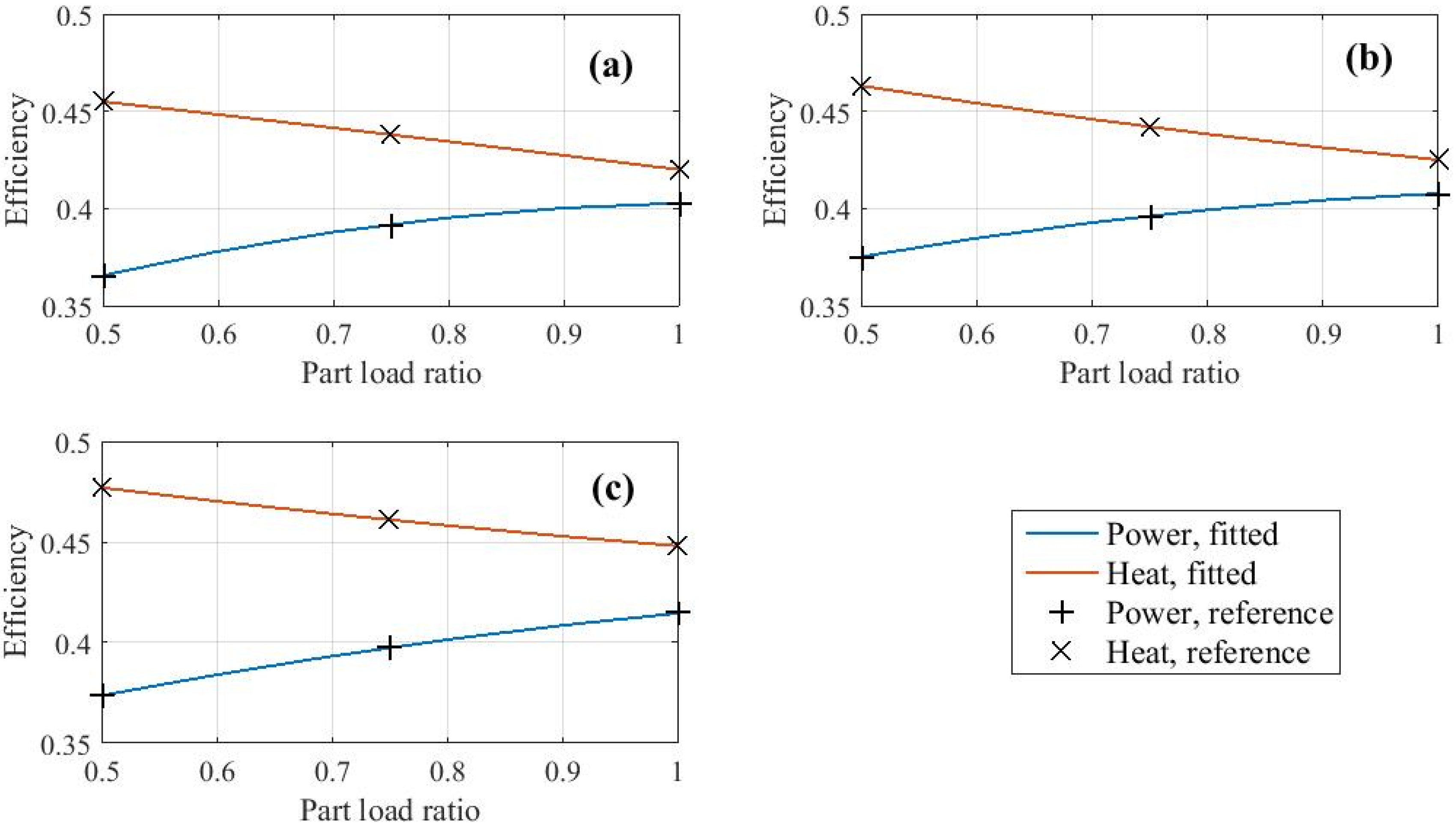
3.3. Combined Heat and Power Plant
| Rated kWe | PLR | ηp | ηh | Ap | Bp | Cp | Ah | Bh | Ch |
|---|---|---|---|---|---|---|---|---|---|
| 499 | 1 | 0.403 | 0.420 | 0.267 | 0.260 | −0.124 | 0.486 | −0.058 | −0.008 |
| 0.75 | 0.392 | 0.438 | |||||||
| 0.5 | 0.366 | 0.455 | |||||||
| 1063 | 1 | 0.408 | 0.425 | 0.305 | 0.179 | −0.076 | 0.518 | −0.126 | 0.033 |
| 0.75 | 0.396 | 0.442 | |||||||
| 0.5 | 0.375 | 0.463 | |||||||
| 1790 | 1 | 0.415 | 0.448 | 0.306 | 0.163 | −0.054 | 0.518 | −0.094 | 0.024 |
| 0.75 | 0.398 | 0.461 | |||||||
| 0.5 | 0.374 | 0.477 |

4. Scheduling Algorithm
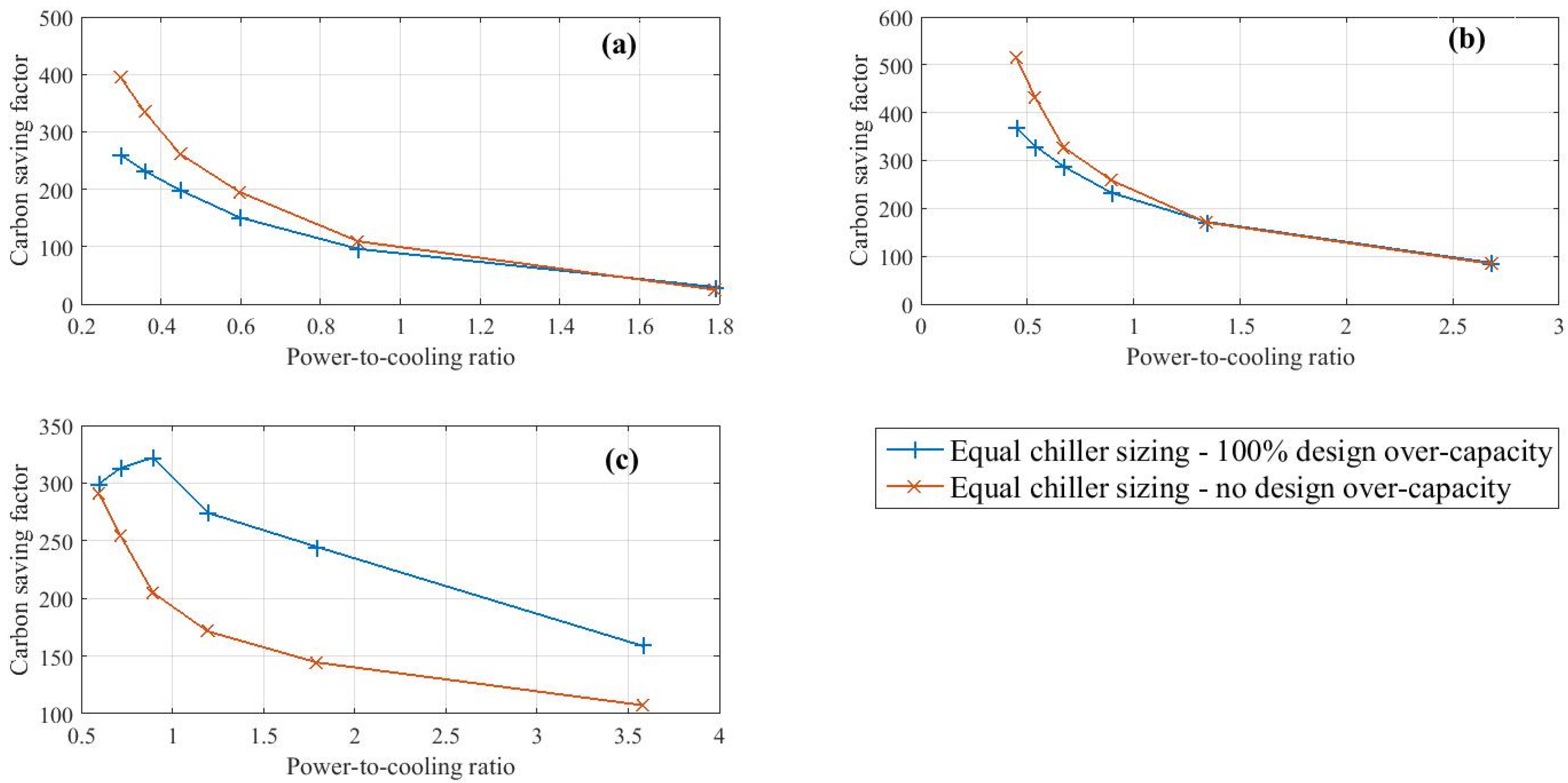
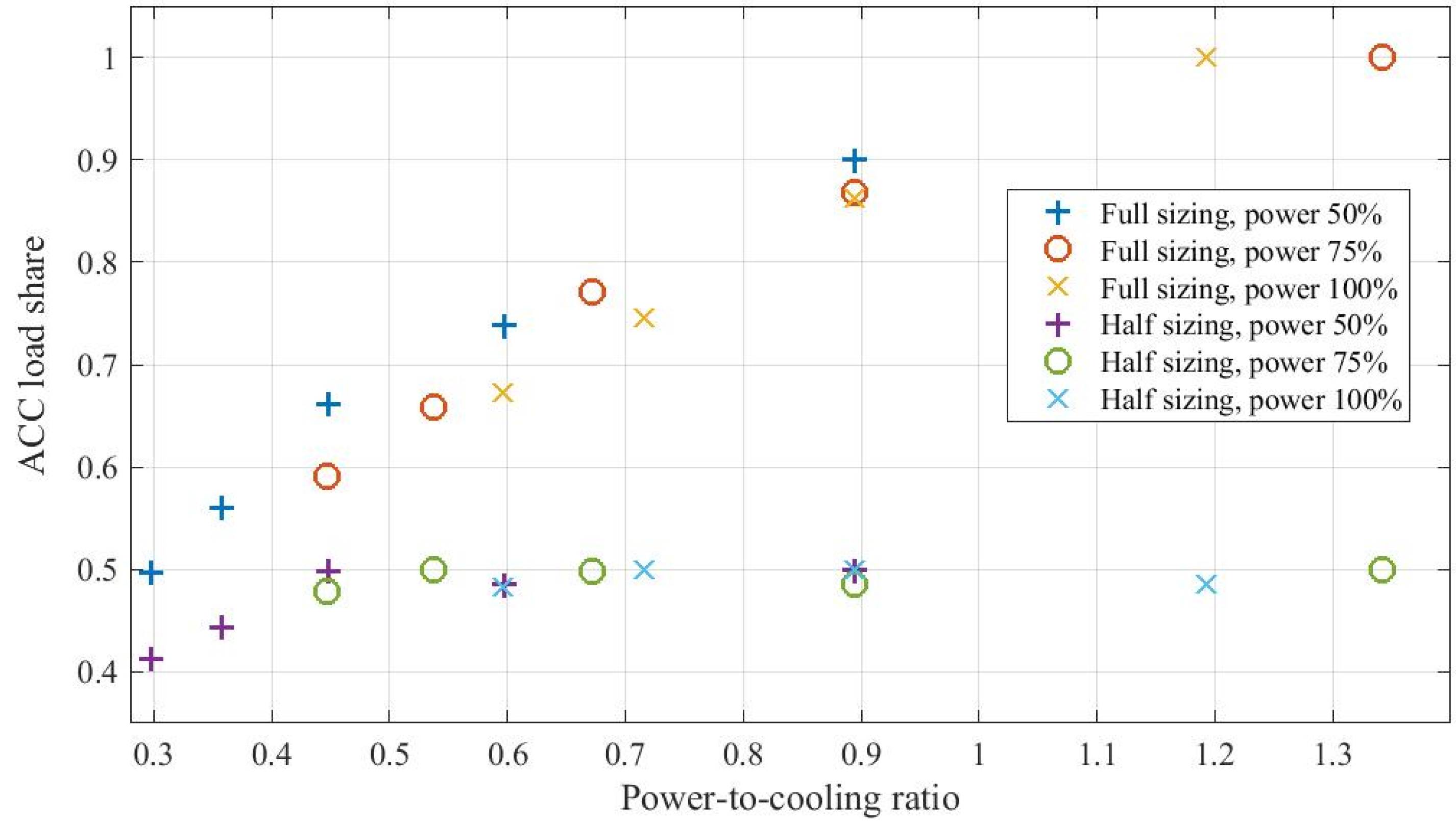
5. Application, Results and Discussion


5.1 Discussion
6. Conclusions
Author Contributions
Conflicts of Interest
List of Symbols
| Symbol | Meaning |
| A | Impeller flow discharge area (m2) |
| ACCshare | Cooling proportion met by absorption cycle chiller (dimensionless) |
| Ap…Cp, Ah…Ch | Power and heat efficiency model fitting coefficients (dimensionless) |
| CF | Cost function (dimensionless) |
| CoP | Coefficient of performance (dimensionless) |
| cp | Specific heat capacity (kJkg-1K-1) |
| D | Impeller diameter (m) |
| E | Electricity demand (kW) |
| F | CHP model fuel energy (kW) |
| F | Zero function heat balance vector (kW) |
| f | Fuel/electricity price ratio (dimensionless) |
| H | CHP plant heat energy and heat demand (kW) |
| h | Enthalpy (kJkg-1) |
| J | Jacobian matrix (dimensionless) |
| kWe, MWe | As energy rate units – the ‘e’ implies electrical power |
| m, m’ | Mass flow rate (kgs-1) – prime superscript denotes design conditions |
| N | Rotational speed (RPS) |
| P | Pressure (Nm-2, bar); fuel/electricity tariff price (money units/kWh) |
| p | Weak solution flow adjustment factor (dimensionless) |
| PLR | Part load ratio (dimensionless) |
| Q | Heat rate (kW) |
| Q | Absorber, condenser heat rate vector (kW) |
| R | Gas constant (kJkg-1K-1) |
| S | Money or carbon saving (currency units or kg) |
| T | Temperature (oC, K) |
| U | Peripheral impeller speed (ms-1) |
| V | Volume flow rate (m3s-1) |
| w | Impeller width at discharge (m) |
| v | Specific volume (m3kg-1) |
| X | Mass concentration (dimensionless or percent) |
| Z | Compressibility factor (dimensionless) |
| β | Impeller angle subtended with respect to horizontal (degree) |
| ΔQ | User-supplied integration interval (kW) |
| ΔX | Concentration differential with solidus state (percent) |
| γ | Index of compression of a perfect gas (dimensionless) |
| η | Efficiency, utilisation (dimensionless) |
| ε | Heat exchanger effectiveness (dimensionless) |
| Subscript | Implication/meaning |
| a | Absorber |
| ac | Air conditioning |
| ACC | Absorption cycle chiller |
| bp | Boiler plant |
| c | Condenser |
| car | Carbon |
| chp | Combined heat and power |
| chw | Chilled water |
| clg | Cooling water |
| com | Compressor |
| crit | Critical (state) |
| dem | Demand (in the context of additional heat) |
| e | Evaporator, electricity (context dependent) |
| f | Fuel |
| g | Generator |
| hw | Heating water |
| hx | Heat exchanger |
| i | Inlet |
| im | Import |
| imp | Impeller |
| loss,fixed | Fixed part of compressor power loss |
| o | Outlet |
| p | Power |
| P | Pressure |
| r | Refrigerant |
| s, ss | Strong solution |
| top | Top-up |
| VCC | Vapour compression chiller |
| w, sw | Weak solution |
Appendix
| Variable | Data | ||||||||
|---|---|---|---|---|---|---|---|---|---|
| Rated capacity (kW) | 250 | 500 | 750 | 1000 | 1250 | 1500 | 2000 | 2500 | 3000 |
| mew (kgs-1) | 12 | 24 | 36 | 51 | 60 | 72 | 96 | 120 | 144 |
| mcw (kgs-1) | 15 | 30 | 45 | 64 | 75 | 90 | 120 | 150 | 180 |
| mhw (kgs-1) | 10 | 20 | 30 | 43 | 50 | 60 | 80 | 100 | 120 |
| msw (kgs-1) | 2.21 | 4.24 | 6.48 | 8.57 | 11.04 | 12.79 | 17.17 | 21.54 | 27.61 |
| Tchw,o (oC) | 7 | ||||||||
| Tclgw,i (oC) | 30 | ||||||||
| Thw,i (oC) | 95 | ||||||||
| ε (all heat exchangers) | 0.75 | ||||||||
| Variable | Data | ||||||||
|---|---|---|---|---|---|---|---|---|---|
| Rated capacity (kW) | 250 | 500 | 750 | 1000 | 1250 | 1500 | 2000 | 2500 | 3000 |
| mew (kgs-1) | 12 | 24 | 36 | 51 | 60 | 72 | 96 | 120 | 144 |
| mcw (kgs-1) | 12 | 24 | 36 | 51 | 60 | 72 | 96 | 120 | 144 |
| D (mm) | 83 | 92 | 99 | 107 | 110.3 | 113.9 | 119.4 | 124.0 | 127.5 |
| Wloss (kW) | 2.5 | 5.5 | 7.5 | 10.0 | 12.5 | 15.0 | 20.0 | 25.0 | 30.0 |
| α | 0.15 | ||||||||
| Rated speed (RPS) | 667 | ||||||||
| w (mm) | 10 | ||||||||
| β (degree) | 130 | ||||||||
| Tchw,o (oC) | 7 | ||||||||
| Tclgw,i (oC) | 30 | ||||||||
| Refrigerant type | R134a | ||||||||
| ε (all heat exchangers) | 0.75 | ||||||||
References
- Moya, M.; Bruno, J.C.; Eguia, P.; Torres, E.; Zamora, I.; Coronas, A. Performance analysis of a trigeneration system based on a micro gas turbine and an air-cooled, indirect fired, ammonia-water absorption chiller. Appl. Energy 2011, 88, 4424–4440. [Google Scholar]
- Ho, J.C.; Chua, K.J.; Chou, S.K. Performance study of a microturbine system for cogeneration application. Renew. Energy 2004, 29, 1121–1133. [Google Scholar] [CrossRef]
- Clausse, M.; Meunier, F.; Coulie, J.; Herail, E. Comparison of adsorption systems using natural gas fired fuel cell as heat source, for residential air conditioning. Int. J. Refri. 2009, 32, 712–719. [Google Scholar] [CrossRef]
- Chua, K.J.; Chou, S.K; Yang, W.M.; Yan, J. Achieving better energy-efficient air conditioning—A review of technologies and strategies. Appl. Energy 2013, 104, 87–104. [Google Scholar] [CrossRef]
- Ryan, W. Driving absorption chillers using heat recovery. ASHRAE J. 2004, 46, S31–S38. [Google Scholar]
- Piacentino, A.; Barbaro, C.; Cardona, F.; Gallea, R.; Cardona, E. A comprehensive tool for efficient design and operation of polygeneration-based energy μgrids serving a cluster of buildings. Part I: Description of the method. Appl. Energy 2013, 111, 1204–1221. [Google Scholar] [CrossRef]
- Piacentino, A.; Barbaro, C. A comprehensive tool for efficient design and operation of polygeneration-based energy μgrids serving a cluster of buildings. Part II: Analysis of the applicative potential. Appl. Energy 2013, 111, 1222–1238. [Google Scholar] [CrossRef]
- Mago, P.; Chamra, L. Analysis and optimization of CCHP systems based on energy, economical, and environmental considerations. Energy Build. 2009, 41, 1099–1106. [Google Scholar] [CrossRef]
- Department of Energy and Climate Change. Table 3.4.1; Quarterly Energy Prices September 2009; Department of Energy and Climate Change: London, UK, 2009; p. 40. [Google Scholar]
- Karmacharya, S.; Putrus, G.; Underwood, C.P.; Mahkamov, K.; McDonald, S.; Alexakis, A. Simulation of energy use in buildings with multiple micro generators. Appl. Therm. Eng. 2014, 581–592. [Google Scholar] [CrossRef]
- Cardona, E.; Piacentino, A. A methodology for sizing a trigeneration plant in Mediterranean areas. Appl. Therm. Eng. 2003, 23, 1665–1680. [Google Scholar] [CrossRef]
- Lozano, M.; Carvalho, M.; Serra, L. Operational strategy and marginal costs in simple trigeneration systems. Energy 2009, 34, 2001–2008. [Google Scholar] [CrossRef]
- Piacentino, A.; Gallea, R.; Cardona, F.; Brano, V.L.; Ciulla, G.; Catrini, P. Optimization of trigeneration systems by mathematical programming: Influence of plant scheme and boundary conditions. Energy Convers. Manag. 2015. [Google Scholar] [CrossRef]
- Chicco, G.; Mancarella, P. Trigeneration primary energy saving evaluation for energy planning and policy development. Energy Policy 2007, 35, 6132–6144. [Google Scholar] [CrossRef]
- Kavvadias, K.; Tosios, A.; Maroulis, Z. Design of a combined heating, cooling and power system: Sizing, operation strategy selection and parametric analysis. Energy Convers. Manag. 2010, 51, 833–845. [Google Scholar] [CrossRef]
- Facci, A.L.; Andreassi, L.; Ubertini, S. Optimisation of CHCP (combined heat power and cooling) systems operations strategy using dynamic programming. Energy 2014, 66, 387–400. [Google Scholar] [CrossRef]
- Kavvadias, K.C.; Maroulis, Z.B. Multi-objective optimisation of a trigeneration plant. Energy Policy 2010, 38, 945–954. [Google Scholar] [CrossRef]
- Kong, X.; Wang, R.; Huang, X. Energy optimization model for a CCHP system with available gas turbines. Appl. Therm. Eng. 2005, 25, 377–391. [Google Scholar] [CrossRef]
- Kong, X.; Wang, R.; Li, Y.; Huang, X. Optimal operation of a micro-combined cooling, heating and power system driven by a gas engine. Energy Convers. Manag. 2009, 50, 530–538. [Google Scholar] [CrossRef]
- Yik, F.W.H.; Lai, J.H.K.; Fong, N.K.; Leung, P.H.M.; Yuen, P.L. A case study on the application of air- and water-cooled oil-free chillers to hospitals in Hong Kong. Build. Serv. Eng. Res. Technol. 2012, 33, 263–279. [Google Scholar] [CrossRef]
- Bourdouxhe, J.-P.; Grodent, M.; Lebrun, J. Reference Guide for Dynamic Models of HVAC Equipment; American Society of Heating, Refrigerating and Air-conditioning Engineers: Atlanta, GA, USA, 1998. [Google Scholar]
- National Institute of Standards and Technology. REFPROP: Reference Fluid Thermodynamic and Transport Properties, Version 7; National Institute of Standards and Technology: Gaithersburg, MD, USA, 2007. [Google Scholar]
- American Society of Heating, Refrigerating and Air Conditioning Engineers (ASHRAE). In Handbook of Fundamentals; American Society of Heating, Refrigerating and Air Conditioning Engineers: Atlanta, GA, USA, 2013; p. 71.
- American Society of Heating, Refrigerating and Air Conditioning Engineers (ASHRAE). In Handbook of Fundamentals; American Society of Heating, Refrigerating and Air Conditioning Engineers: Atlanta, GA, USA, 2013; p. 70.
- Underwood, C.P. Chapter 2; HVAC Control Systems—Modelling, Analysis and Design; E & FN Spon: London, UK, 2002; pp. 52–60. [Google Scholar]
- American Society of Heating, Refrigerating and Air Conditioning Engineers (ASHRAE). In Handbook of Fundamentals; American Society of Heating, Refrigerating and Air Conditioning Engineers: Atlanta, GA, USA, 2013; pp. 17–18.
- Trane Classic Absorption Series (model 294). Available online: http://www.trane.com/download/equipmentpdfs/absprc005en.pdf (accessed on 3 July 2015).
- GE Distributed Power—Jenbacher types 3 and 6 gas engines. Available online: https://www.ge-distributedpower.com/products/power-generation (accessed on 4 July 2015).
- Department of Energy and Climate Change. Table 3.4.1; Quarterly Energy Prices March 2015; Department of Energy and Climate Change: London, UK, 2015; p. 40. [Google Scholar]
- Greenhouse Gas Conversion factor Repository. Available online: http://www.ukconversionfactorscarbonsmart.co.uk/ (accessed on 5 July 2015).
© 2015 by the authors; licensee MDPI, Basel, Switzerland. This article is an open access article distributed under the terms and conditions of the Creative Commons Attribution license (http://creativecommons.org/licenses/by/4.0/).
Share and Cite
Underwood, C.; Ng, B.; Yik, F. Scheduling of Multiple Chillers in Trigeneration Plants. Energies 2015, 8, 11095-11119. https://doi.org/10.3390/en81011095
Underwood C, Ng B, Yik F. Scheduling of Multiple Chillers in Trigeneration Plants. Energies. 2015; 8(10):11095-11119. https://doi.org/10.3390/en81011095
Chicago/Turabian StyleUnderwood, Chris, Bobo Ng, and Francis Yik. 2015. "Scheduling of Multiple Chillers in Trigeneration Plants" Energies 8, no. 10: 11095-11119. https://doi.org/10.3390/en81011095
APA StyleUnderwood, C., Ng, B., & Yik, F. (2015). Scheduling of Multiple Chillers in Trigeneration Plants. Energies, 8(10), 11095-11119. https://doi.org/10.3390/en81011095