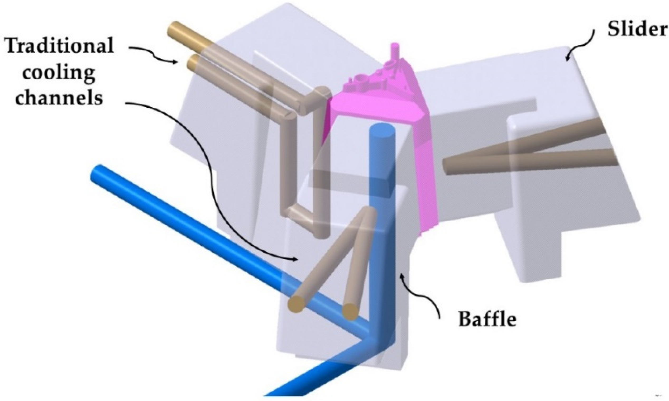
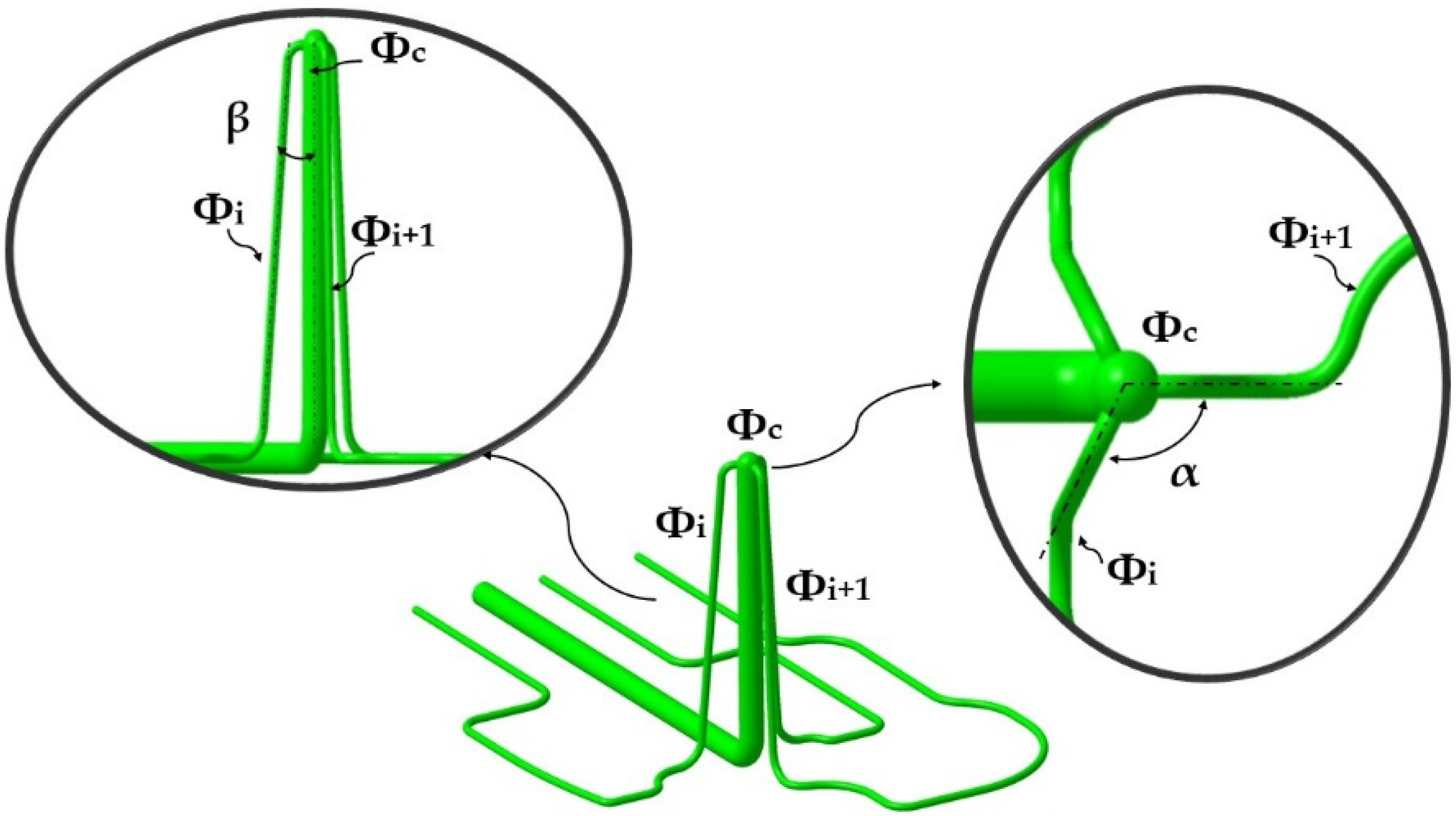
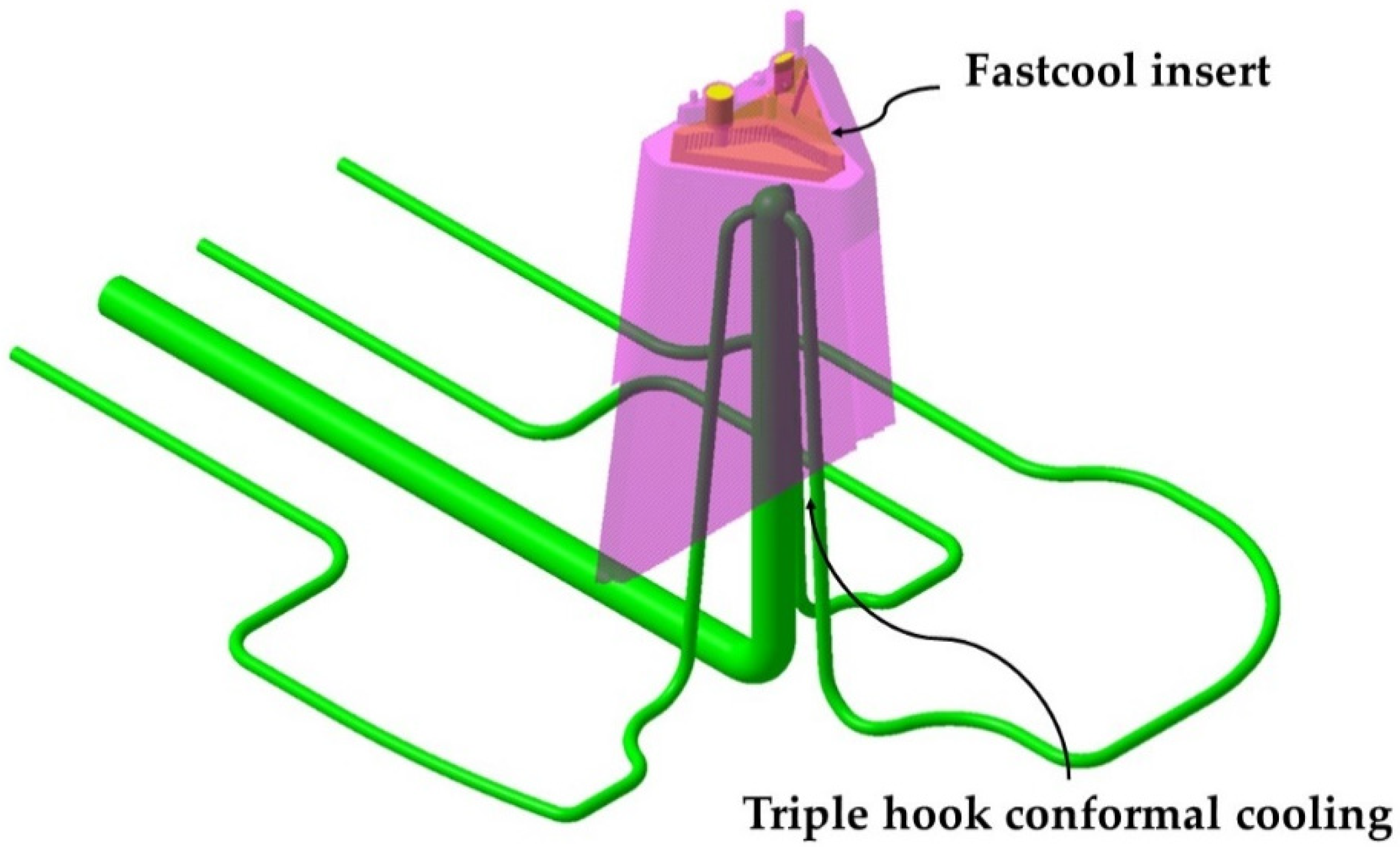
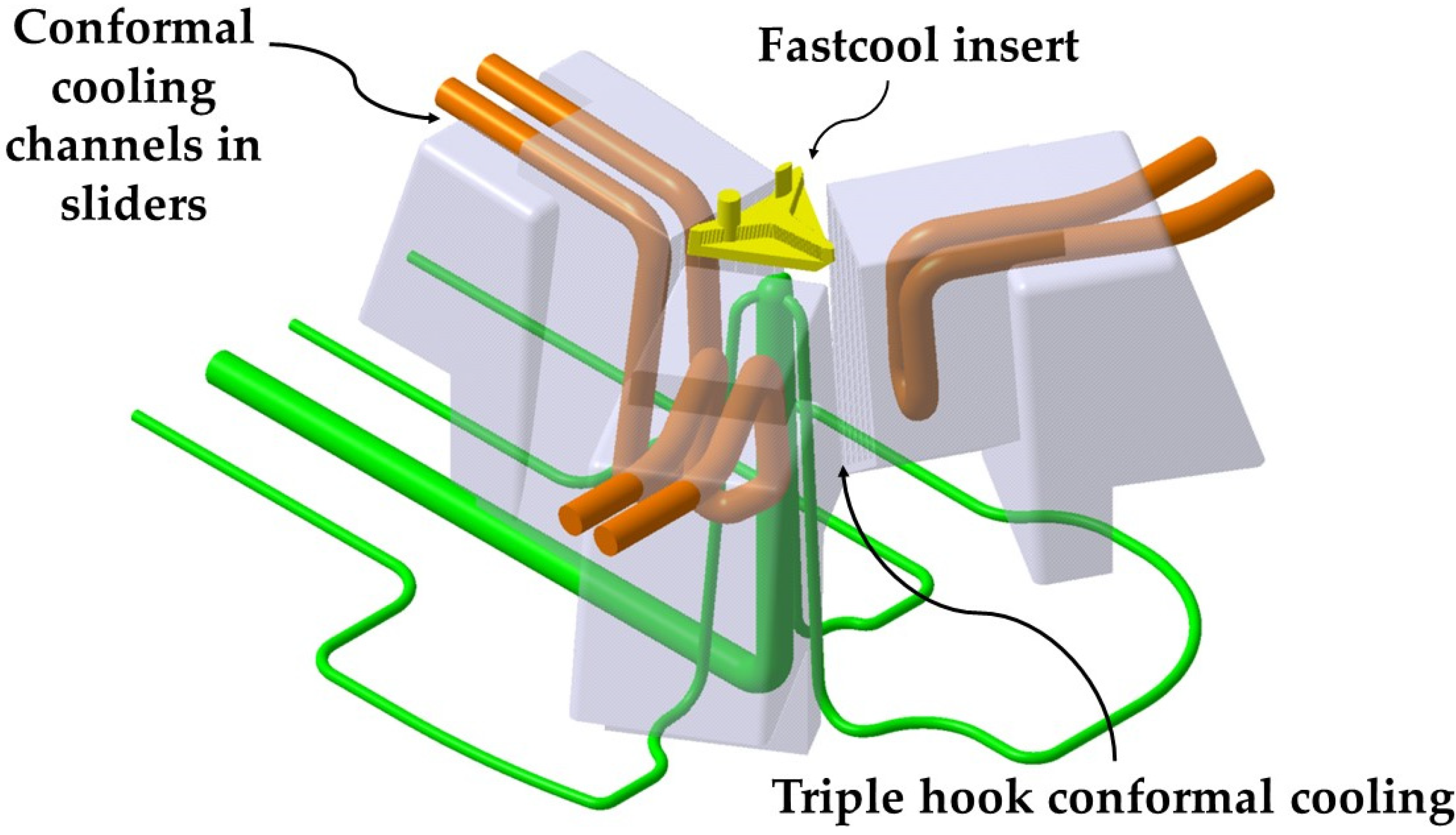
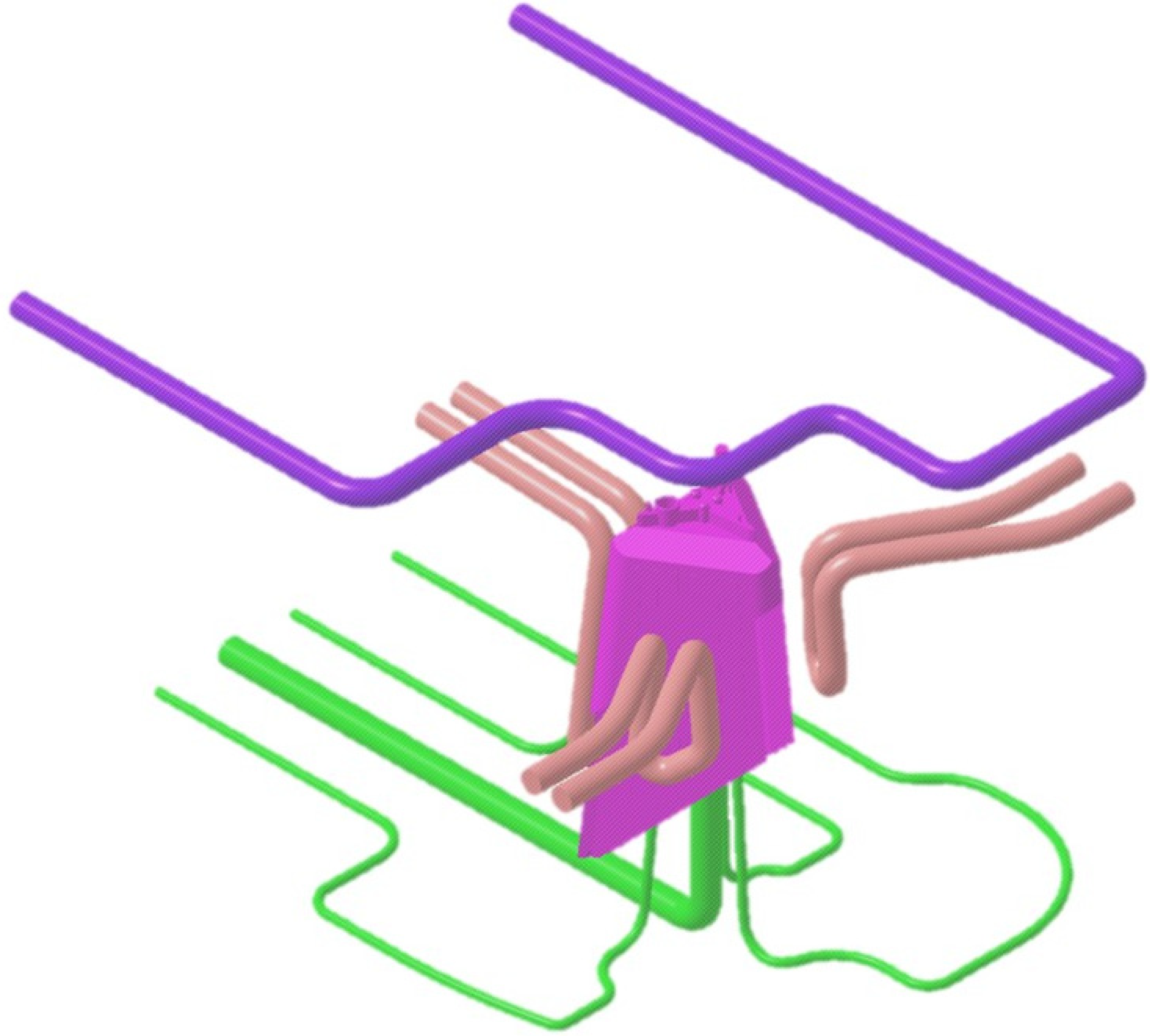
In this manuscript, two proposals for the design of the cooling system for the plastic part under study are presented and compared. On the one hand, the current traditional cooling system with perforated straight channels whose manufacture is carried out using traditional machining processes and tools. And, on the other hand, a new optimized cooling system that combines conformal triple hook-shaped cooling channels with a fastcool-type metal insert. So, the manufacture of this proposal is based mainly on the 3D additive manufacturing process using laser sintering (SLS). Additive manufacturing technologies are line with current sustainability requirements. The SLM additive manufacturing process allows the manufacture of conformal channels adapted to the free shape of the geometric surface of the plastic part [
30,
31]. The geometric CAD design of both configurations is performed using the Catia V5—6R2020 3D CAD geometric modeling software [
32]. Likewise, to evaluate and analyze the thermal and technological parameters that define the cooling phase of the plastic part, numerical simulations of a thermal type are modeled using the numerical and commercial software Moldex3D R17-CoreTech System Taiwan, [
33]. In this way, the results of the thermal and technological parameters obtained from both proposed cooling system configurations can be compared, establishing the one that optimizes and improves, on the one hand, the cooling phase of the plastic part, as well as the thermal efficiency. Both the 3D CAD modeling process and the numerical analysis of the different cooling system configurations proposed in this manuscript have been carried out using an MSI notebook with an Intel (R) Core- Intel corporation EEUU(TM) i-77700HQ CPU @ 2.80 GHz.
Thermal Modeling of Numerical Simulations
The definition of rheological and thermal simulations using CAE numerical software allows the analysis of the cooling phase of a plastic part and how the main elements of the injection mold and the most representative technological parameters of said phase influence and interact. Likewise, the results of the parameters obtained from the numerical simulations allow establishing whether the design of the main elements that make up the cooling system, meets the minimum industrial technical requirements that are established to validate the manufacture of the plastic part. In this section, the preprocessing configuration used for each of the different numerical simulations carried out is detailed. At the beginning of this preprocessing phase, the discretization of the different geometric elements to be analyzed numerically must be defined. That is, the three-dimensional meshes for the geometric elements of the injection mold must be defined, as well as the geometric parameters that define them. The commercial software Moldex 3D R17 [
33] has a Moldex Designer meshing module, in which the geometric parameters of the meshes created can be configured and established.
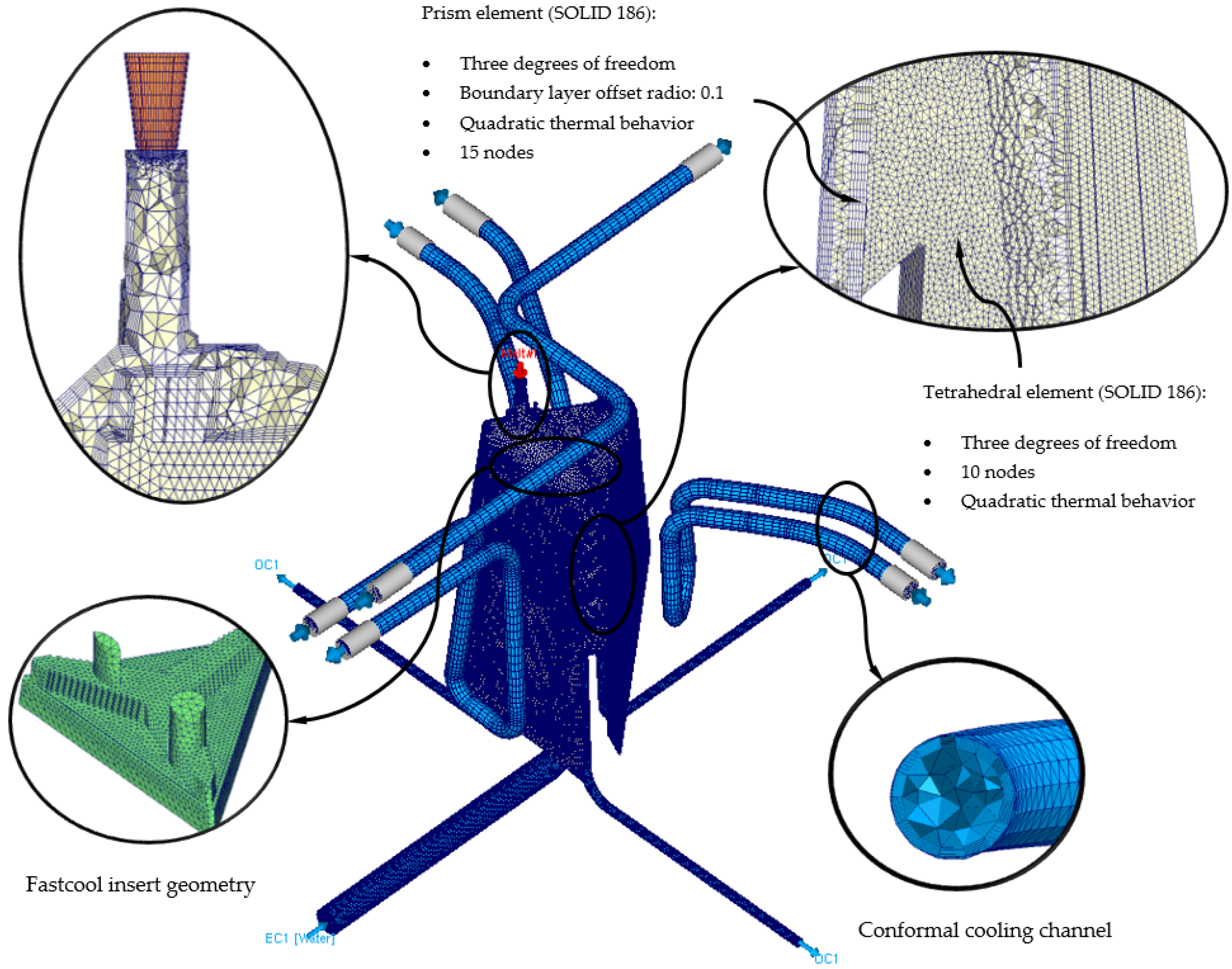
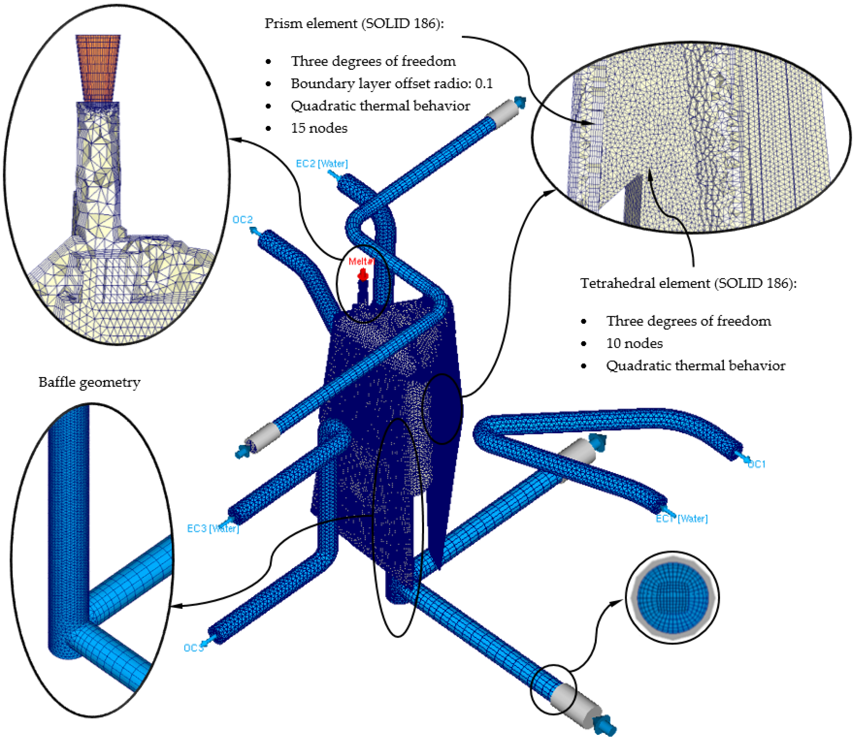
Table 3 shows the magnitude of the geometric parameters used during the meshing process, as well as their configuration. Said geometric parameters have been adjusted to the smallest and most relevant geometric detail or precision of the plastic part under study. However, the selection of the type of element used is important when carrying out the meshing process. In this way, three-dimensional elements of the second-order tetrahedron have been selected, called SOLID 186. These elements have 10 main nodes, located at the vertex of the tetrahedron, and 4 secondary nodes, located at the midpoint of the edges of the tetrahedron (see
Figure 9). In addition, each of said nodes has 3 degrees of freedom in the main coordinate axes, notably improving the precision of the temperature field parameters and displacements in the solution obtained. Besides that, and in order to improve the precision of the numerical simulation, a series of three-dimensional elements of the prism type have been defined along the contact surfaces between the different elements that make up the injection mold. Elements are placed on the surface of the cooling channels or between the surface of the plastic part and the cavity and core surface of the injection mold cavity. These elements have 6 main nodes located at the vertices of the prism, and 9 secondary nodes located at the midpoint of the edges of the prism (see
Figure 9). Furthermore, each of said nodes has 3 degrees of freedom in the main coordinate axes. The selection of this type of element is established by the “Boundary Layer Mesh” operation, which establishes a series of layers from the interface surfaces previously mentioned (see
Figure 10). The average length of these elements is configured from an offset ratio or percentage of the size of the average element of the mesh. In this case, and as
Table 3 shows, the offset ratio selected for the generation of the meshes is 0.1 and the number of Boundary Layers is equal to 5. The use of this meshing operation allows modeling with greater precision the roughness generated between the surface of the cooling channels and the coolant flow, as well as the layer of solidified plastic material that is generated when the molten plastic front comes into contact with the surfaces of the injection mold cavity.
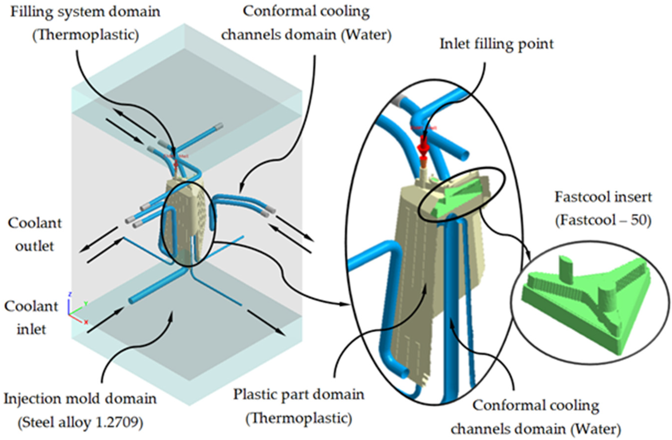
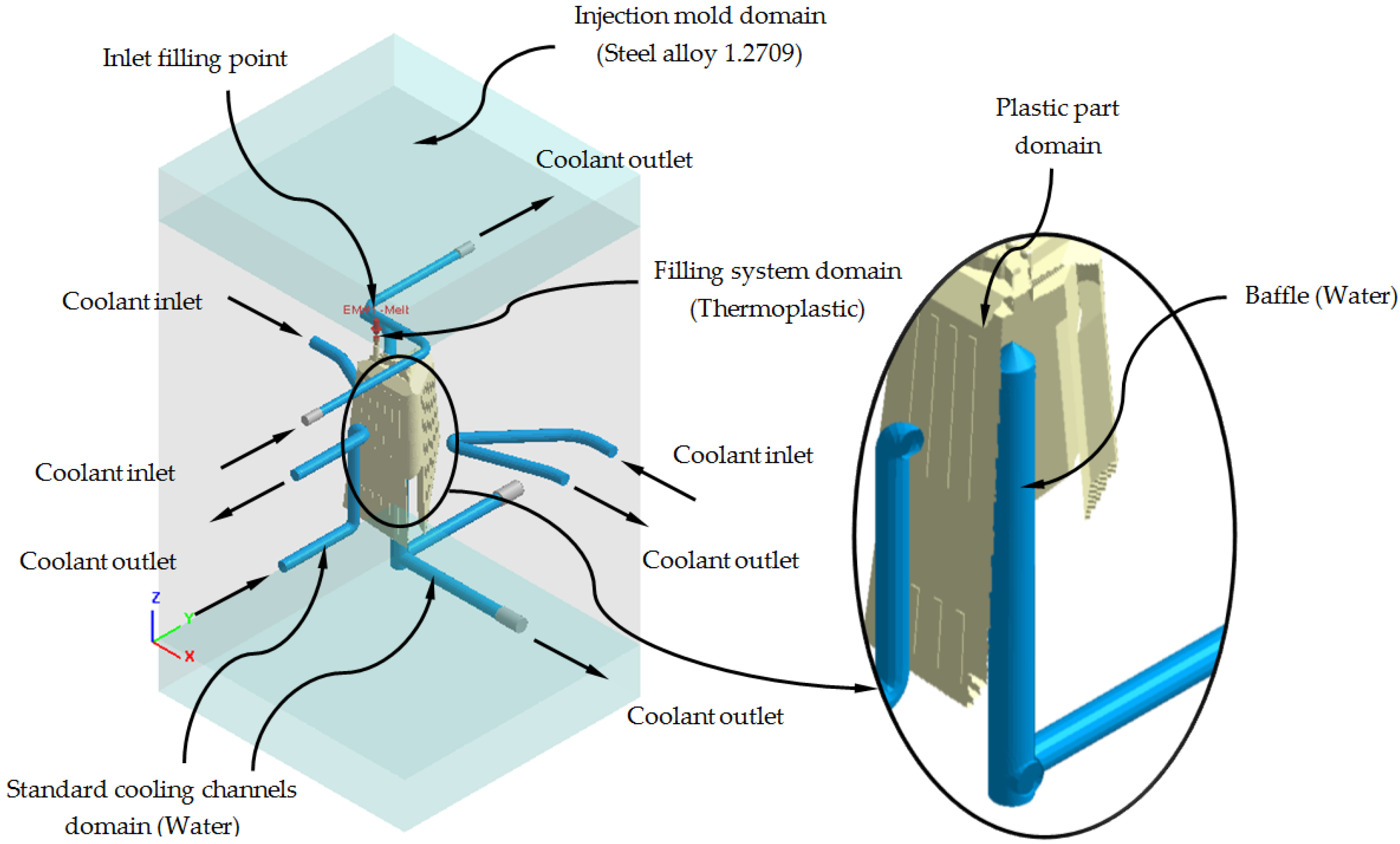
Next, we proceed to define the material assigned to each one of the elements of the injection mold and the plastic part, as well as the physical, thermal, and rheological properties of each one of them. As shown in
Figure 11, the plastic part is manufactured from the thermoplastic material PC Lexan 121 R [
28]. The main feed channel, from which the filling of the mold cavity begins, has associated, like the plastic part, the PC Lexan 121 R thermoplastic material. For the cooling channels, both for the traditional configuration and for the conformal configuration, the material water is defined as the coolant flow. For the geometry defined as injection mold, the assigned metal material is a P20 steel alloy, and finally, for the Fastcool insert, used in the conformal cooling system solution, the metallic material used is a Fastcool-50 steel alloy.
Table 4 shows the magnitude of the physical, thermal and rheological properties defined in the numerical simulations for each material used. As can be seen, the use of a Fastcool insert, whose metallic material is Fastcool-50 [
27], considerably improves the thermal properties of the metallic material of the mold. In this way, the area of the plastic part that is in contact with the Fastcool insert will present greater heat exchange and, therefore, will improve thermal efficiency throughout the cooling phase. Therefore, as shown in
Figure 11, said Fastcool insert is located in the inner central core of the plastic part. Well, in this region a large amount of residual heat accumulates and presents greater difficulty to be uniformly re-cooled, with respect to the rest of the geometric regions of the plastic part.
Likewise, the definition of the thermoplastic material in the simulation software must be accompanied by numerical models that allow the modeling of both the behavior of the viscosity of the material and the behavior of its PVT curve. In addition, the manufacturer of the material [
29] recommends the magnitude of a series of temperatures for each of the phases of the manufacturing cycle of the plastic part.
Table 5 shows the parameters recommended by the manufacturer and the viscosity and PVT curve models of the thermoplastic material defined in the numerical simulation software.
As shown in
Figure 11 and
Figure 12, each numerical analysis carried out has associated a set of boundary conditions, which establish the technological parameters of pressure and initial temperature for the input of the molten plastic front to the injection mold cavity and the flow of the coolant flow to the cooling channels. For the input of the molten plastic front to the injection mold cavity, the upper surface of the main feed channel (see
Figure 11) is established as a boundary condition, an injection temperature of 295 °C, and a maximum injection pressure of 160 MPa. For the cooling channels, firstly, both the inlet and outlet surfaces of the coolant flow are defined (see
Figure 11); secondly, an initial temperature of the coolant flow of 80 °C is determined, and finally, a pressure magnitude that allows the front of the coolant flow to develop in turbulent regime. That is, the Reynolds number of the coolant flow along the cooling channels is greater than 1.5 × 10
4. Likewise, and according to the recommended parameters offered by the manufacturer of the thermoplastic material, the initial temperature of the injection mold is set at 80 °C.
Table 6 shows the magnitude of the technological parameters used in the modeling of the filling and cooling phase of the numerical simulations carried out for the present case study.
To complete the definition of the preprocessing phase of the numerical simulations carried out, the following configurations relative to the solver used to solve the numerical models of the simulations carried out are defined:
The analysis of the cooling phase of the plastic part is carried out in a transitory regime or “Cooling transient”. Given the defined cooling time (see
Table 6), the solver analyzes the process and the evolution of the cooling of the plastic part over time. This type of analysis allows obtaining and saving solutions of the field of temperatures and displacements for different time intervals. The time interval defined in each numerical simulation carried out is 10 s.
The modeling of the coolant flow along the cooling channels is done with the “Run 3D cooling channels” operation. This operation makes it possible to define a roughness magnitude on the surfaces of the cooling channels and improves the analysis of turbulence on their surface. The magnitude of the defined roughness is equal to 0.02 mm.
The type of solver used is the maximum variation of mold temperature and its convergence criteria are temperature difference equal to 1 °C and maximum cycle number equal to 10 cycles.
After completing the definition of the pre-processing phase of the different numerical analyzes performed, the set of thermal and rheological results obtained is presented. From their analysis and evaluation, it is determined that the configuration of the triple hook-shaped conformal cooling channels for cores together with the use of conformal cooling channels adapted to the sliders and the Fastcool insert optimizes the cooling phase and improves the efficiency and thermal performance of the injection mold for the plastic part object of study.
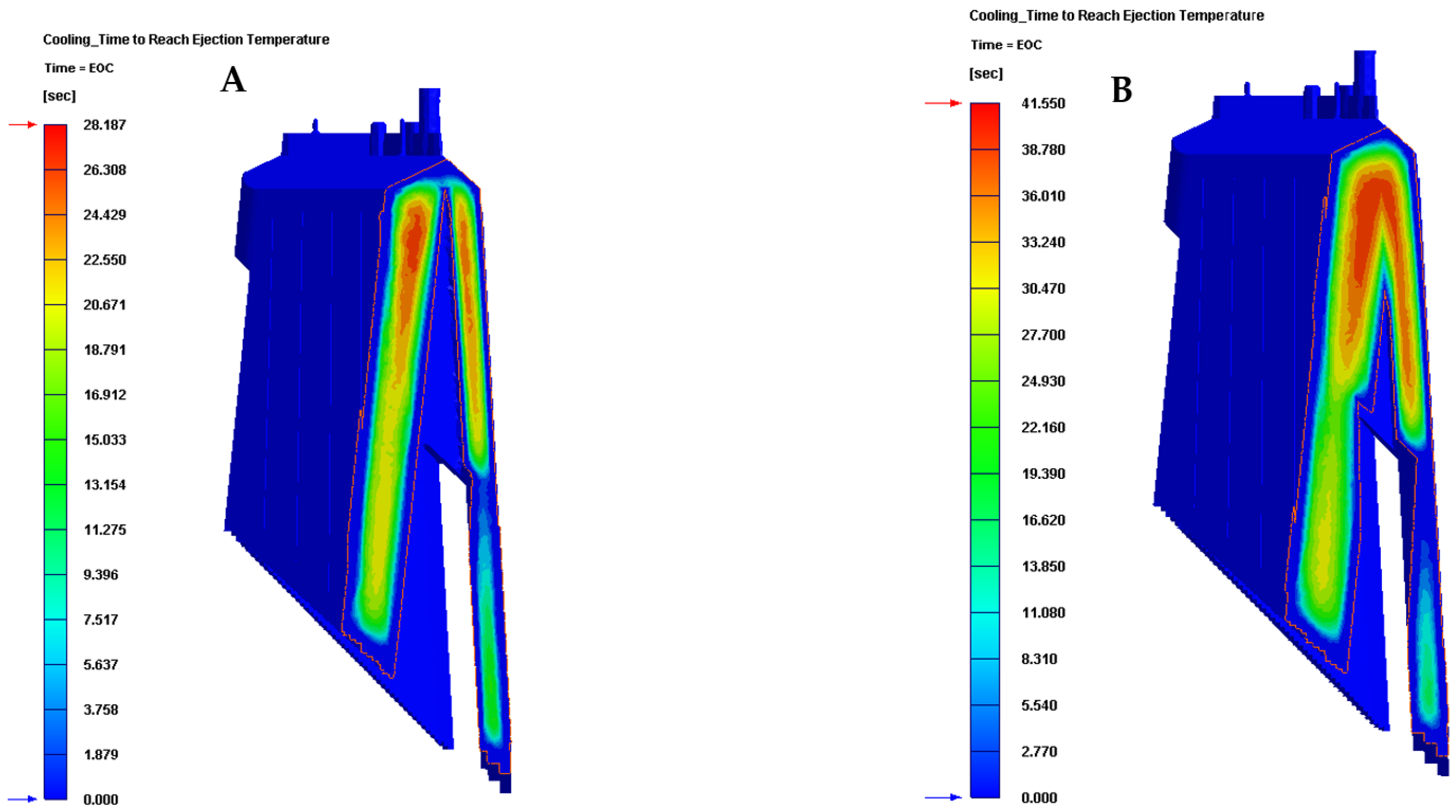
Firstly,
Table 7 and
Figure 13 show the results obtained for the parameter time to reach the ejection temperature of the plastic part for each of the cooling system configurations proposed in this manuscript.
In this way, the results presented in
Table 7 and
Figure 13 show that the new configuration of the conformal cooling system presented in this paper, together with the use of a Fastcool insert, improves the time until reaching the ejection temperature of the plastic part, with respect to the configuration of the current traditional cooling system. Therefore, it can be determined that the use of this new type of conformal cooling channels, accompanied by an insert with high thermal performance, reduces the cycle time of the plastic part under study by 13.363 s or by 32.161%, compared to the classical geometry and configuration of perforated straight cooling channels.
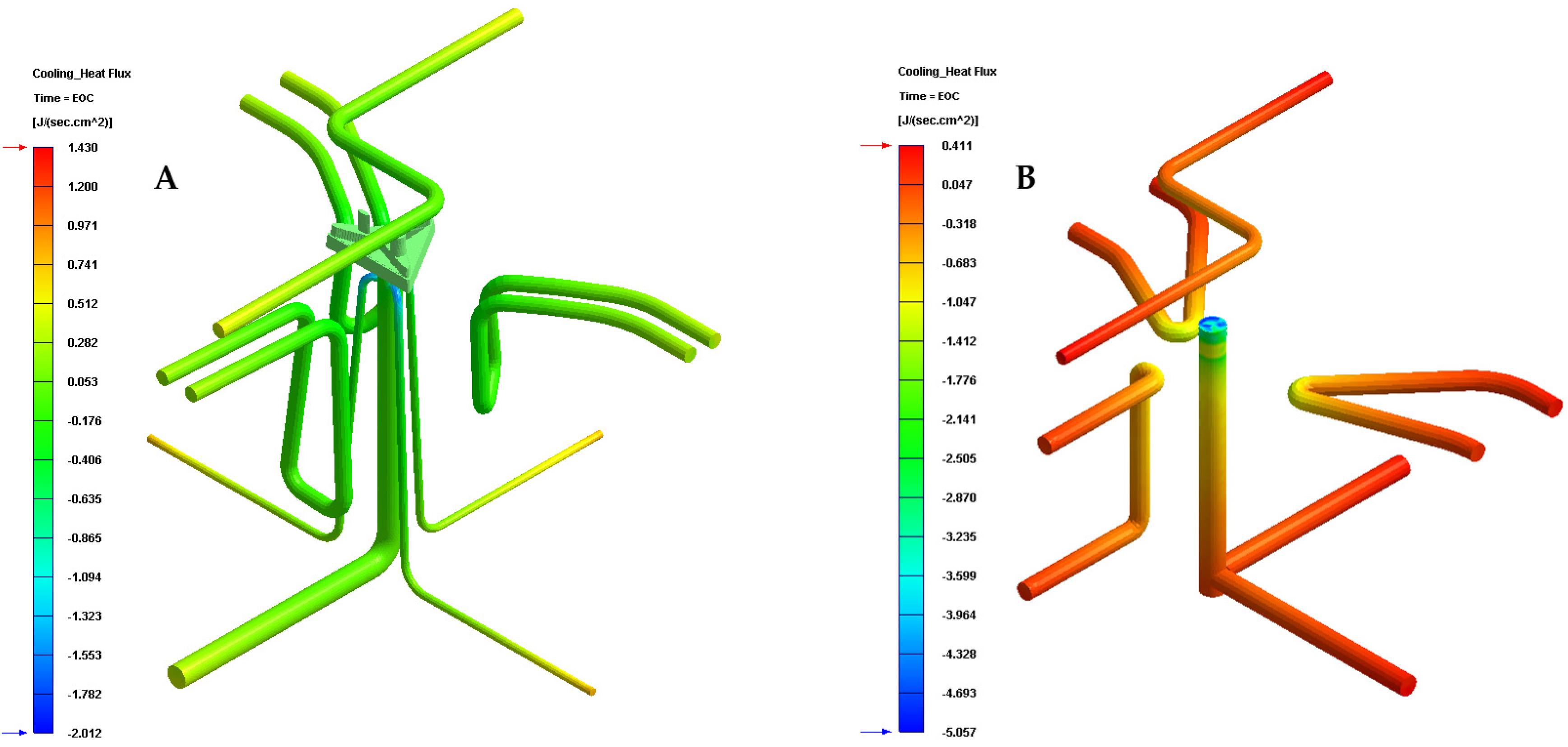
Table 8 and
Figure 14 show the results obtained for the heat flow parameter that is exchanged between the cooling mechanisms and the plastic part, for each of the cooling system configurations proposed in this manuscript.
Likewise, the results presented in
Table 8 and
Figure 14 show that the configuration of the new presented conformal cooling system, together with the use of a Fastcool insert, increases and optimizes the heat flow exchanged between the plastic part and the different cooling mechanisms defined for cooling the plastic part. In particular, the increase in heat exchange produced, compared to the standard cooling configuration, is 2.062 J/s·cm
2, which translates into an improvement in thermal efficiency of 267.10%.
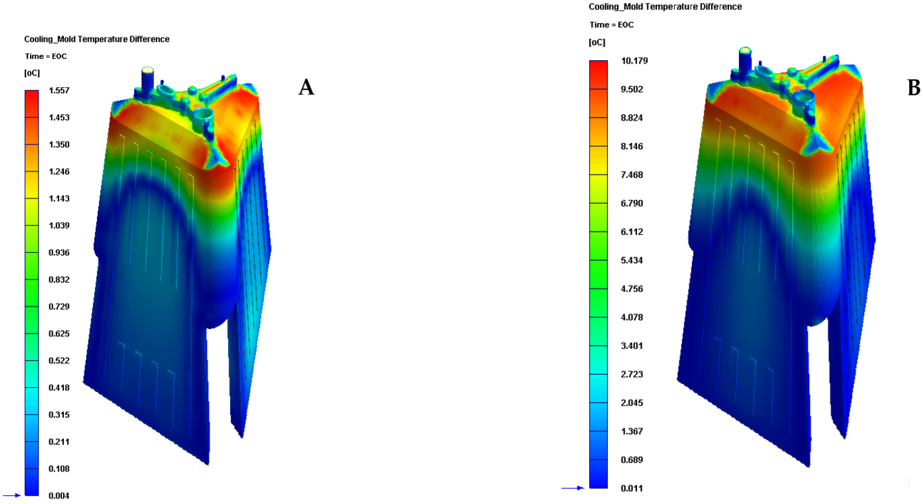
Table 9 and
Figure 15 show the results obtained for the temperature gradient along the surface of the plastic piece under study in this manuscript.
The results presented in
Table 9 and
Figure 15 show that the configuration of the new conformal cooling system, together with the use of a Fastcool insert, reduces the temperature gradient along the surface of the plastic part concerning the traditional cooling system configuration. In particular, this reduction represents an improvement of 84.701% in the uniformity of the temperature map throughout the plastic part under study. In addition, the new conformal cooling channel solution, together with the Fastcool insert, meets the industrial validation requirements of the manufacture of the plastic part since the magnitude of the temperature gradient on the surface of the plastic part is less than 10 °C. However, for the traditional cooling system, this condition is very close to being fulfilled.
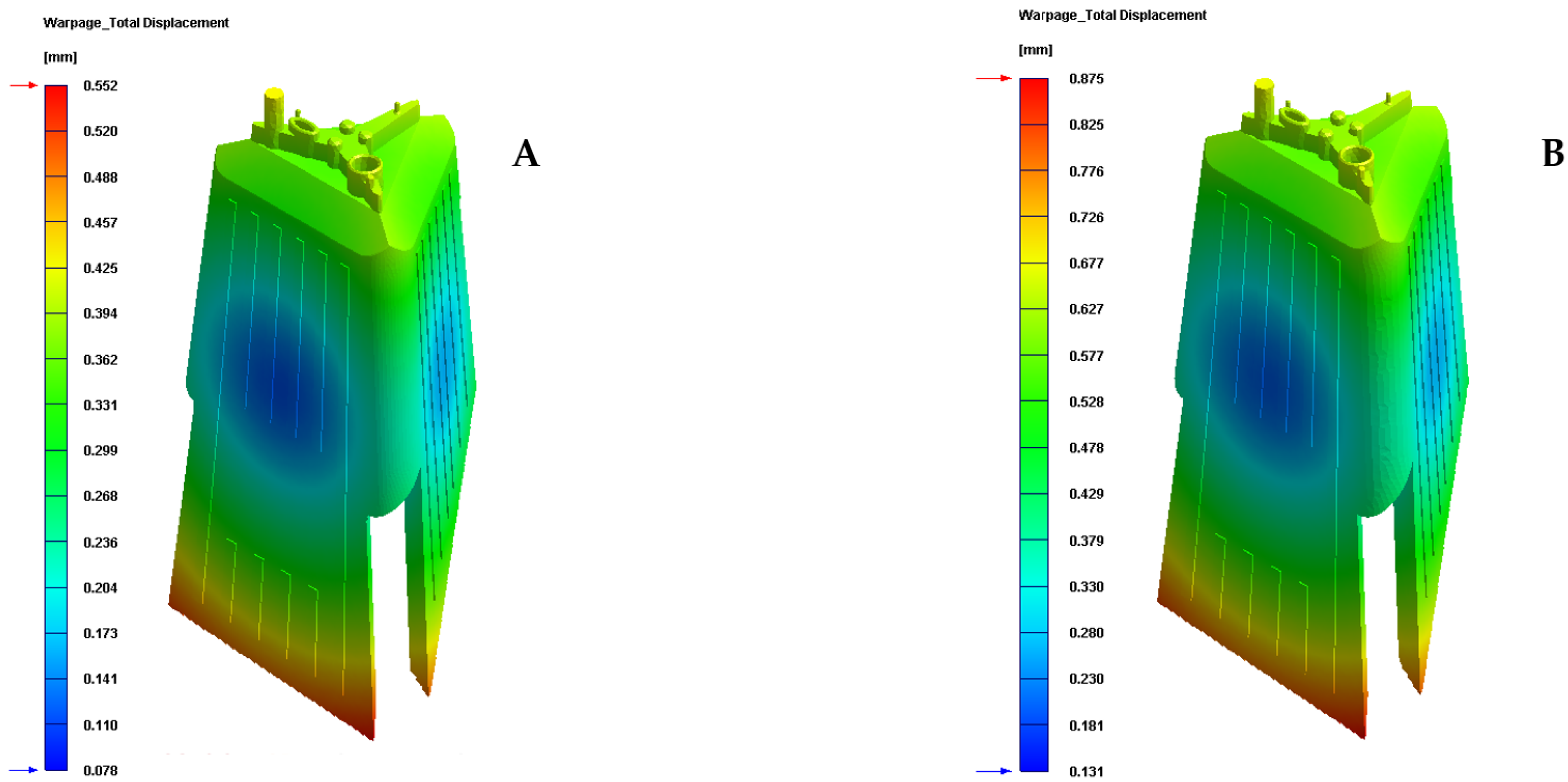
Finally, given that the plastic part under study is an optical lighting part, it is important to analyze and check the field of displacements and the map of residual stresses resulting after the manufacturing process.
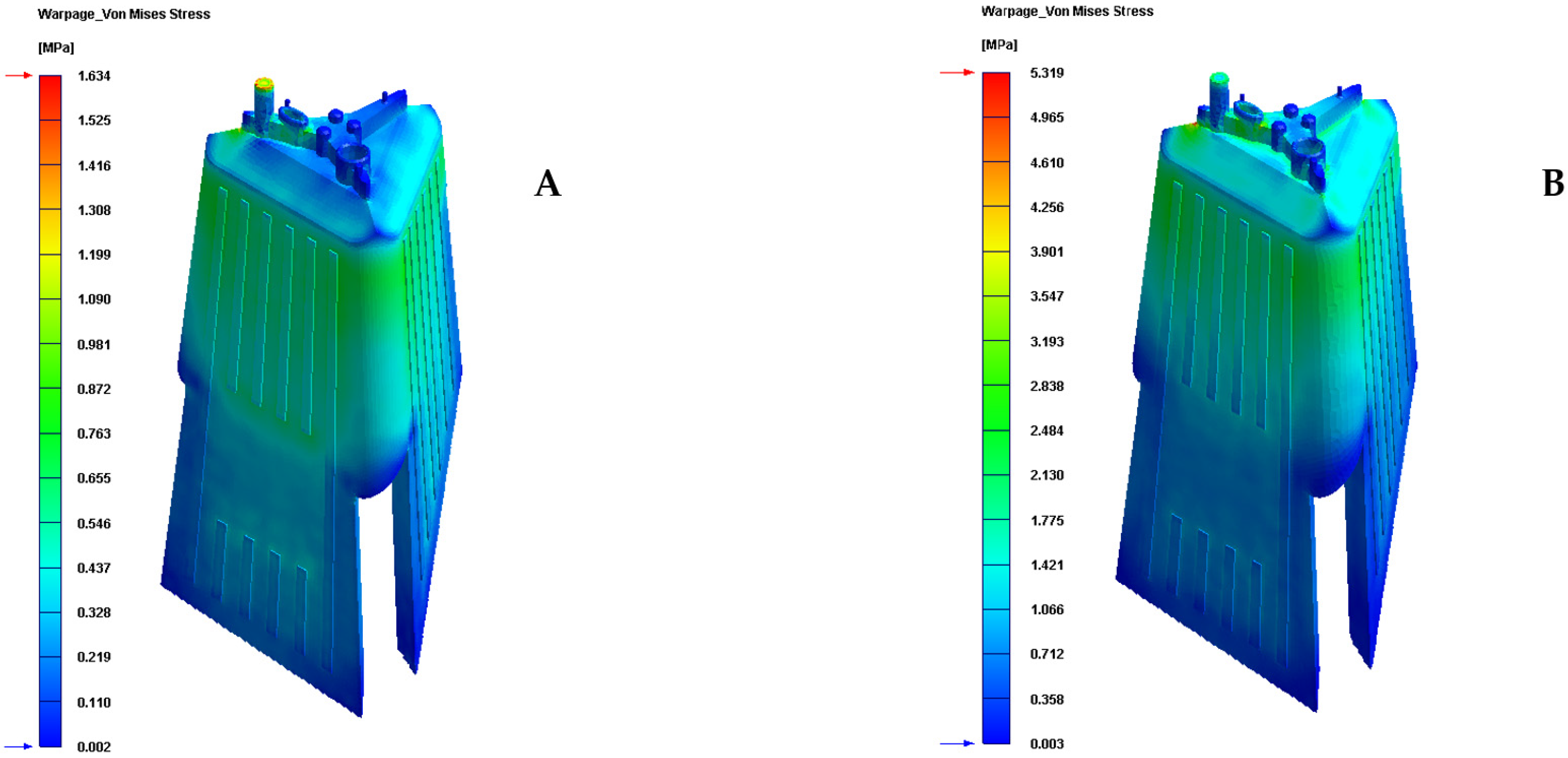
Table 10 and
Table 11 and
Figure 16 and
Figure 17 show the displacement field and the residual stress map of Von—Mises along with the geometry of the plastic part under study after the cooling phase.
As can be seen, for the new conformal cooling system with a Fastcool insert, the increase in uniformity in the temperature gradient of the surface of the plastic part causes a decrease and improvement in the field of displacement and the map of residual stresses on the plastic part. In particular, the total maximum displacements are reduced by 0.318 mm and the Von—Mises maximum residual stress by 3.685 MPa in comparison to the results obtained for the traditional cooling system. Likewise, the improvement obtained in these technological parameters makes it possible to achieve the optical and functional requirements established for the correct operation and validation of the plastic part under study in this manuscript.


 ,
, 


