
Mathematical Model for the Movement of Two-Pipe Vehicles in a Straight Pipe Section

Abstract
:1. Introduction
2. Establishment of Mathematical Models
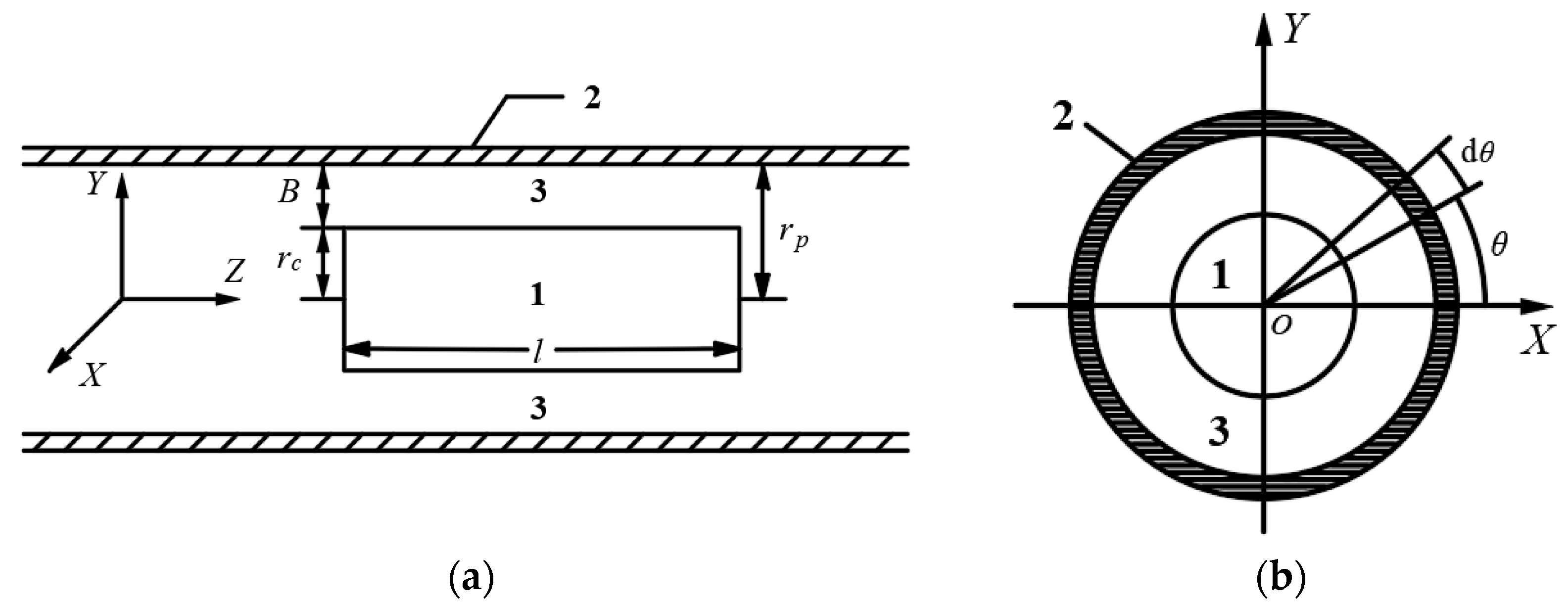
2.1. Mathematical Model of Concentric Annular Gap Flow
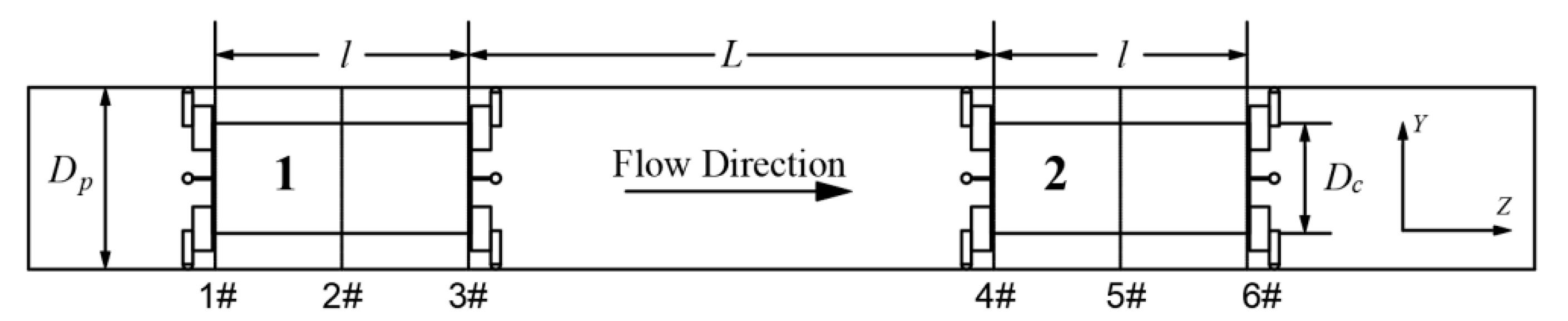
2.2. Mathematical Model of the Two-Pipe Vehicles
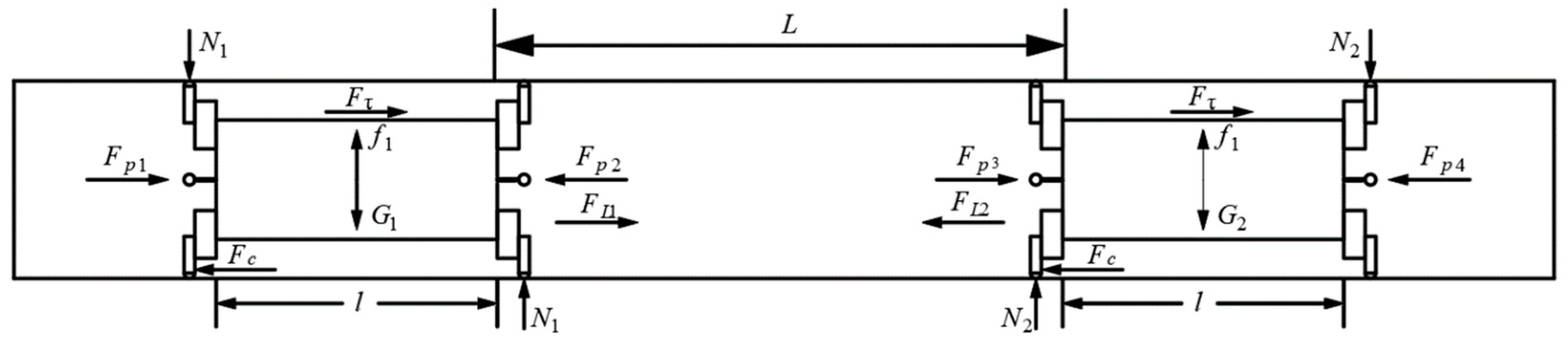
2.2.1. Force Analysis of the Two-Pipe Vehicles
2.2.2. Mechanical Equilibrium Equation for Stable Movement of the Two-Pipe Vehicles
2.2.3. Motion Equation for Stable Movement of the Two-Pipe Vehicles
3. Experimental Methods
3.1. Experimental System and Procedures
- (1)
- The power device used in this experiment is a high-power centrifugal pump, and the adjustment device includes a control valve (gate valve) and an electromagnetic flowmeter.
- (2)
- The delivery device is made of trumpet-shaped stainless steel material, with a gate valve installed on the upper part, as shown in Figure 7a. The pipe vehicle starting device is installed 1.6 m downstream of the delivery device. When the pipe vehicle enters the pipeline, the starting device is in a closed state. When the pipe vehicle needs to be moved in the pipeline, the starting device is opened to release the pipe vehicle. The receiving device consists of three parts: A rectangular water tank, a baffle, and a plastic collection box, as shown in Figure 7b.
- (3)
- The experimental instrument mainly includes a two-pipe vehicles timing device and a flow field measurement device. The two-pipe vehicles timing device consists of an infrared probe and a display, as shown in Figure 8. Infrared probes are installed near the launching device and the outlet of the pipeline, respectively. When the two-pipe vehicles passes the first infrared probe, the timing starts, and the timing stops when it passes the second probe. According to the speed formula, the average movement speed of the two-pipe vehicles can be calculated. The flow field measurement device is a Laser Doppler Velocimeter (LDV). In order to reduce the refraction of the laser light by the pipe wall, a rectangular water jacket filled with water was added to the test pipe section.
- (4)
- The conveying pipe used in this test is composed of steel and plexiglass pipes. The lengths of the steel and plexiglass pipes are 8.6 m and 21.3 m, respectively, the thickness of the pipe wall is 5 mm, and the outer diameter of the pipe is 110 mm. The entire pipeline is formed by connecting multiple sections of plexiglass tubes through flanges, and a height-adjustable support body is installed at intervals below the plexiglass tubes in order to ensure that the plexiglass tubes are at the same level.
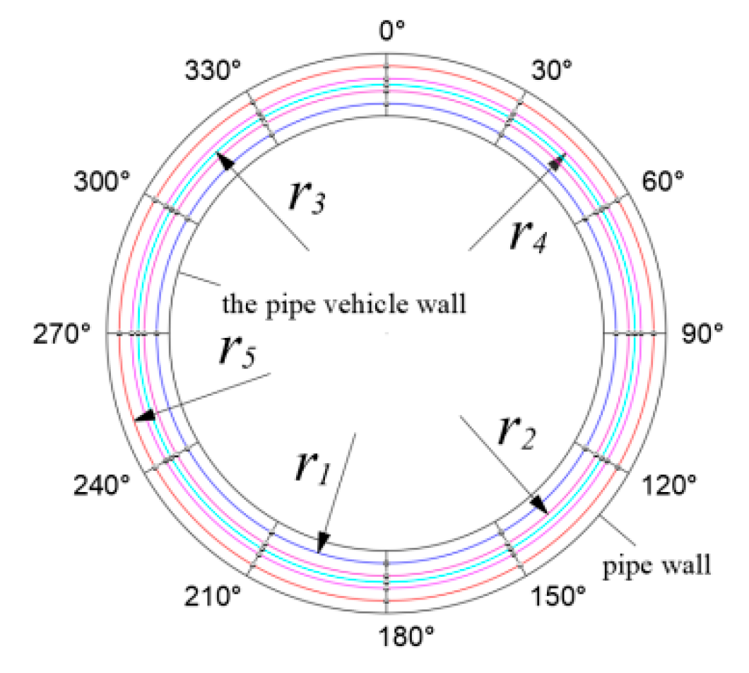
3.2. Section Selection and Measuring Point Arrangement
3.3. Experiment Plan
4. Results and Discussion
4.1. Mathematical Model Verification
4.2. Analysis of Influencing Factors for Two-Pipe Vehicles Movement Speed
- (1)
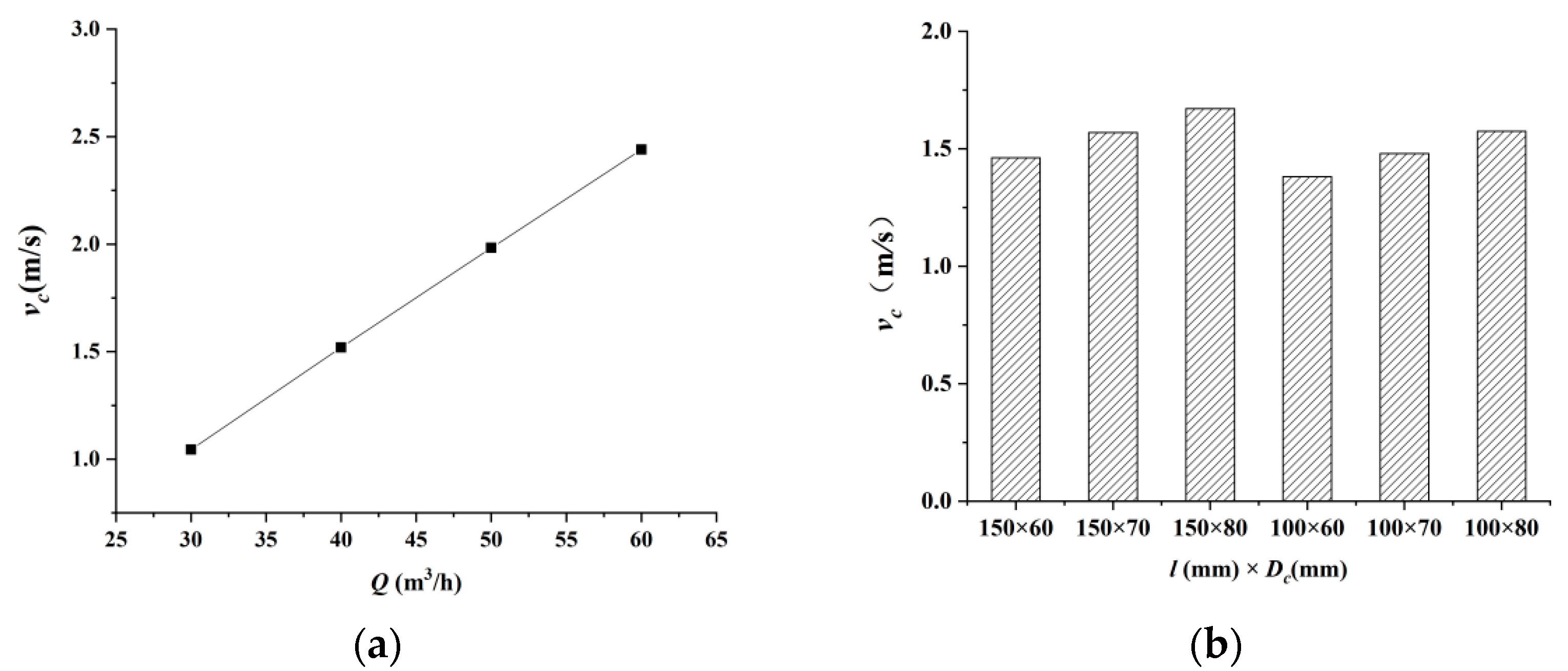
- It can be seen, from Figure 12a, that when the other variables remained unchanged, the average movement speed of the two-pipe vehicles presented a linear relationship with the flow rate. This is mainly due to the pressure difference between the front and rear faces being the main driving force for the two-pipe vehicles. With the continuous increase in the flow rate, the differential pressure force gradually increases. Although the resistance of the pipe vehicle also gradually increases with an increase in the flow rate, the increase in the resistance with the flow rate is less than the increase in the pressure, causing the total power of the two-pipe vehicles to increase. Therefore, the movement speed of the two-pipe vehicles increases gradually with an increase in the flow rate.
- (2)
- It can be seen from Figure 12b that when the length of the vehicle l is held constant, the average movement speed of the two-pipe vehicles increases gradually with an increase in the diameter of the pipe vehicle Dc. This is mainly because, when the diameter Dc increases, the end face area, side wall area, and volume of the two-pipe vehicles increase accordingly. According to Equations (15)–(17), the pressure differential force and wall shear stress on the pipe vehicle gradually increase, while the frictional resistance decreases. The changes in differential pressure force, wall shear stress, and frictional resistance increase the driving force of the two-pipe vehicles, such that the movement speed of the two-pipe vehicles increases accordingly. When the diameter of the pipe vehicle is constant, the average movement speed of the two-pipe vehicles increases gradually with an increase in vehicle length. This is mainly because the longer the body length l, the larger the body side wall surface area and the body volume, such that the wall shear stress increases while the frictional resistance decreases and, so, the total driving force of the two-pipe vehicles increases. Therefore, the average movement speed of the two-pipe vehicles also increases. By comparing the experimental results, it can be seen that the average movement speed increment of the two-pipe vehicles caused by the change of diameter Dc is greater than that caused by the change in the vehicle length l.
- (3)
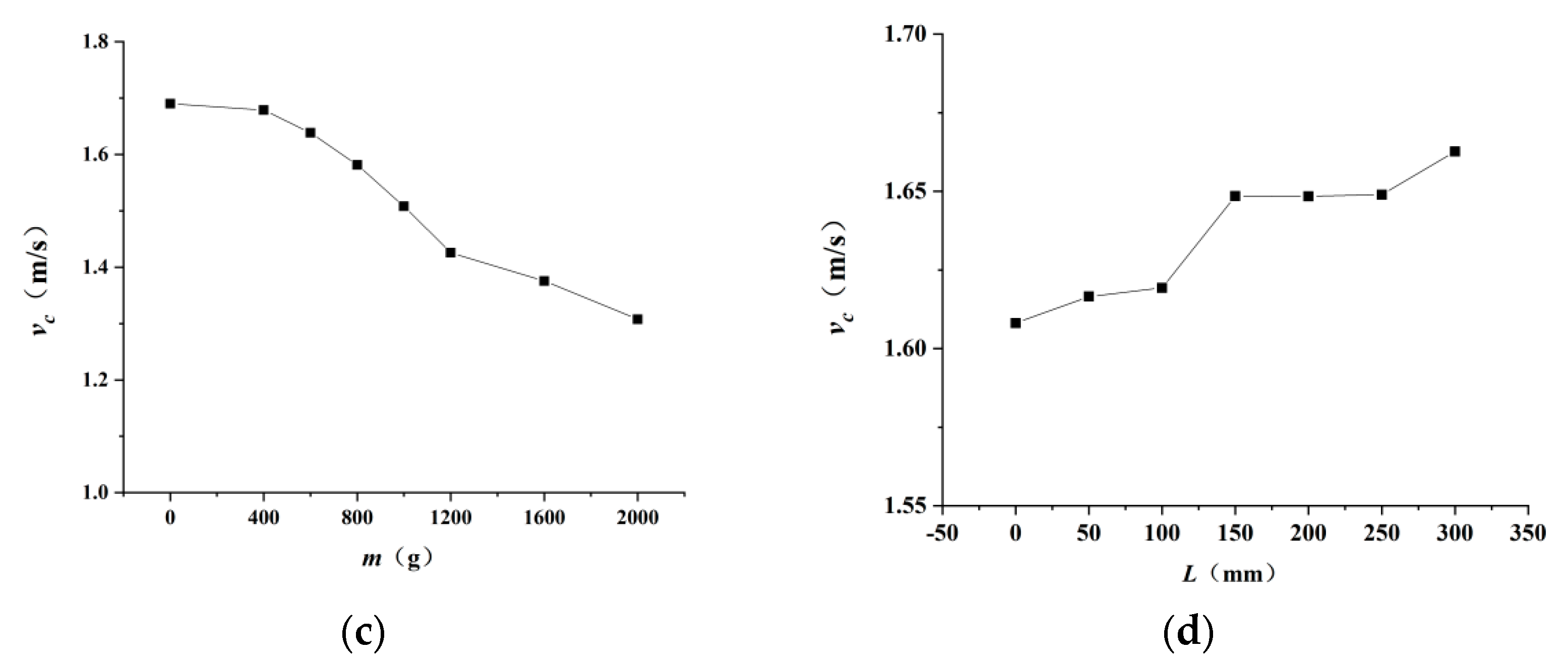
- It can be seen from Figure 12c that with an increase in the conveyed load, the movement speed of the two-pipe vehicles shows a gradually decreasing trend. This is mainly due to the fact that when the model of the pipe vehicle is kept constant, the buoyancy of the two-pipe vehicles does not change; however, when the load increases, the support force of the pipe vehicle increases, and the frictional resistance increases accordingly. Therefore, the movement speed of the two-pipe vehicles is reduced.
- (4)
- It can be seen from Figure 12d that, with an increase in the vehicle spacing, the average movement speed of the two-pipe vehicles presents a gradually increasing trend. When the vehicle spacing is relatively small, the two-pipe vehicles can be regarded as a whole, and the pressure drop along the direction of the two-pipe vehicles is small; that is, the pressure difference between the front and rear surfaces of the two-pipe vehicles is small. With an increase in the vehicle spacing, the pressure difference between the front and rear surfaces of the pipe vehicle gradually increases and, thus, the movement speed of the two-pipe vehicles gradually increases. With a further increase in the distance between the vehicles, the influence between the two-pipe vehicles is almost negligible, and the movement speed of the two-pipe vehicles gradually changes to that of a single pipe vehicle moving in the pipeline. When the vehicle spacing reaches 300 mm, the movement of the two-pipe vehicles can basically be regarded as the movement of a single pipe vehicle. As the water flow goes through the flow process of “full pipe–annular gap–vehicle spacing–annular gap–full pipe”, when the two-pipe vehicles move in the pipeline, the energy loss is larger than that of a single pipe vehicle and the kinetic energy obtained by the two-pipe vehicles is smaller than that of a single pipe vehicle, such that the movement speed of the two-pipe vehicles is lower than that of a single pipe vehicle under the same working conditions. It can also be seen from the figure that when the spacing is between 50 mm and 150 mm, the growth rate of the average movement speed of the two-pipe vehicles is larger; that is, the slope of the curve is larger. When the spacing ratio is between 150 mm and 250 mm, the average movement speed of the two-pipe vehicles changes little with an increase in the spacing. When the spacing is greater than 250 mm, the growth rate of the average movement speed of the two-pipe vehicles becomes larger again.
4.3. Research Implications and Limitations
5. Conclusions
Author Contributions
Funding
Institutional Review Board Statement
Informed Consent Statement
Data Availability Statement
Acknowledgments
Conflicts of Interest
References
- Mahdi, V.; Amit, K. Pipeline hydraulic transport of biomass materials: A review of experimental programs, empirical correlations, and economic assessments. Biomass Bioenergy 2015, 81, 70–82. [Google Scholar]
- Xu, H.L.; Chen, W.; Hu, W.G. Hydraulic transport flow law of natural gas hydrate pipeline under marine dynamic environment. Eng. Appl. Comp. Fluid 2020, 14, 507–521. [Google Scholar] [CrossRef]
- Vladimir, A.S. Natural Gas Pipeline Transportation as the Thermodynamic Process. J. Appl. Math. 2021, 9, 211–215. [Google Scholar]
- Umar, H.A.; Abdul Khanan, M.F.; Ogbonnaya, C.; Shiru, M.S.; Ahmad, A.; Baba, A.I. Environmental and socioeconomic impacts of pipeline transport interdiction in Niger Delta, Nigeria. Heliyon 2021, 7, e06999. [Google Scholar] [CrossRef] [PubMed]
- Hodgson, G.W.; Charles, M.E. The pipeline flow of capsules. Can. J. Chem. Eng. 1963, 42, 43–45. [Google Scholar]
- Kruyer, J.; Redberger, P.G.; Ellis, H.S. The pipeline flow of capsules. Fluid Mech. 1967, 30, 513–531. [Google Scholar] [CrossRef]
- Ismail, T.; Ulusarslan, D. Mathematical expression of pressure gradient in the flow of spherical capsule less dense than water. Int. J. Multiphas. Flow 2007, 33, 658–674. [Google Scholar]
- Brown, R.A.S. Capsule pipeline research at the Alberta Research Council. Pipeline 1987, 6, 75–82. [Google Scholar]
- Charles, M.E. Theoretical analysis of the concentric flow of cylindrical forms. Can. J. Chem. Eng. 1963, 41, 46–51. [Google Scholar]
- Ellis, H.S. An experimental investigation of the transport by water of single cylindrical and spherical capsules with density equal to that of the water. Can. J. Chem. Eng. 1964, 42, 69–76. [Google Scholar] [CrossRef]
- Kroonenberg, V.D. A Mathematical Model for Concentric Horizontal Capsule Transport. Can. J. Chem. Eng. 1978, 56, 538–543. [Google Scholar] [CrossRef]
- Latto, B.; Chow, K.W. Hydrodynamic transport of cylindrical capsules in a vertical pipeline. Can. J. Chem. Eng. 1982, 60, 713–722. [Google Scholar] [CrossRef]
- Quadrio, M.; Luchini, P. Direct numerical simulation of the turbulent flow in a pipe with annular cross section. Eur. J. Mech. 2002, 21, 413–427. [Google Scholar] [CrossRef]
- Mohamed, F.; Khalil, S.Z.; Kassab, I.G. Turbulent flow around single concentric long capsule in a pipe. Appl. Math. Model. 2009, 34, 2000–2017. [Google Scholar]
- Taimoor, A.; Mishra, R. Computational fluid dynamics based optimal design of hydraulic capsule pipelines transporting cylindrical capsules. Powder Technol. 2016, 295, 180–201. [Google Scholar]
- Lenau, C.W. Unsteady Flow in Hydraulic Capsule Pipeline. J. Eng. Mech. 1996, 122, 1168–1173. [Google Scholar] [CrossRef]
- Vlasak, P. An experimental investigation of capsules of anomalous shape conveyed by liquid in a pipe. Powder Technol. 1999, 104, 207–213. [Google Scholar] [CrossRef]
- Khalil, M.F.; Hammoud, A.H. Experimental investigation of hydraulic capsule pipeline with drag reducing surfactant. In Proceedings of the 8th International Congress of Fluid Dynamics and Propulsion, Sharm El-Sheikh, Sinai, Egypt, 14–17 December 2006. [Google Scholar]
- Huang, X.; Liu, H.; Thomas, R.M. Polymer drag reduction in hydraulic capsule pipeline. AIChE J. 1997, 43, 1117–1121. [Google Scholar] [CrossRef]
- Taimoor, A.; Abdualmagid, A.; Rakesh, M. Effect of capsule shape on hydrodynamic characteristics and optimal design of hydraulic capsule pipelines. J. Petrol. Sci. Eng. 2018, 161, 390–408. [Google Scholar]
- Swamee, P.K. Design of sediment transporting pipeline. J. Hydraul. Eng. 1995, 121, 72–76. [Google Scholar] [CrossRef]
- Li, Y.Y.; Sun, Y.H. Mathematical Model of the Piped Vehicle Motion in Piped Hydraulic Transportation of Tube-Contained Raw Material. Math. Probl. Eng. 2019, 2019, 3930691. [Google Scholar] [CrossRef]
- Zhang, X.L.; Sun, X.H.; Li, Y.Y. 3-D numerical investigation of the wall-bounded concentric annulus flow around a cylindrical body with a special array of cylinders. J. Hydrodyn. 2015, 27, 120–130. [Google Scholar] [CrossRef]
- Xiao, N.Y.; Ma, J.J.; Li, Y.Y. Wall Stresses in Cylinder of Stationary Piped Carriage Using COMSOL Multiphysics. Water 2019, 11, 1910. [Google Scholar]
- Xiao, N.Y.; Ma, J.J. The Wall Stress of the Capsule Surface in the Straight Pipe. Water 2020, 12, 242. [Google Scholar]
- Jia, X.M.; Sun, X.H.; Song, J.R. Effect of Concentric Annular Gap Flow on Wall Shear Stress of Stationary Cylinder Pipe Vehicle under Different Reynolds Numbers. Math. Probl. Eng. 2020, 2020, 1253652. [Google Scholar] [CrossRef]
- Zhang, C.J.; Sun, X.H.; Li, Y.Y. Effects of Guide Vane Placement Angle on Hydraulic Characteristics of Flow Field and Optimal Design of Hydraulic Capsule Pipelines. Water 2018, 10, 1378. [Google Scholar] [CrossRef]
- Wang, J.; Sun, X.H.; Li, Y.Y. Analysis of Pressure Characteristics of Tube-Contained Raw Material Pipeline Hydraulic Transportation under Different Discharges. In Proceedings of the International Conference on Electrical, Mechanical and Industrial Engineering (ICEMIE), Phuket, Thailand, 24–25 April 2016; pp. 44–46. [Google Scholar]
- Zhang, C.J.; Sun, X.H.; Li, Y.Y. Hydraulic Characteristics of Transporting a Piped Carriage in a Horizontal Pipe Based on the Bidirectional Fluid-Structure Interaction. Math. Probl. Eng. 2018, 2018, 8317843. [Google Scholar] [CrossRef]
- Ulusarslan, D.; Ismail, T. An experimental investigation of the capsule velocity, concentration rate and the spacing between the capsules for spherical capsule train flow in a horizontal circular pipe. Powder Technol. 2005, 159, 27–34. [Google Scholar] [CrossRef]
- Ulusarslan, D.; Ismail, T. An experimental determination of pressure drops in the flow of low density spherical capsule train inside horizontal pipes. Exp Therm Fluid Sci. 2005, 30, 233–241. [Google Scholar] [CrossRef]
- Alam, M.M. Lift Forces Induced by the Phase Lag between the Vortex Sheddings from Two Tandem Bluff. Bodies. J. Fluid Struct. 2016, 65, 217–237. [Google Scholar] [CrossRef]
- Carmo, B.S.; Meneghini, J.R. Numerical investigation of the flow around two circular cylinders in tandem. J. Fluids Struct. 2006, 22, 979–988. [Google Scholar] [CrossRef]
- Taimoor, A.; Mishra, R. Optimal design of hydraulic capsule pipeline transporting spherical capsules. Can. J. Chem. Eng. 2016, 94, 966–979. [Google Scholar]
- Taimoor, A.; Mishra, R. Development of a design methodology for hydraulic pipelines carrying rectangular capsules. Int. J. Press. Ves. Pip. 2016, 146, 111–128. [Google Scholar]


| Q | l × Dc | L | m | Calculated Value | Measured Value | Relative Error |
|---|---|---|---|---|---|---|
| 30 | 150 × 70 | 15 | 600 | 1.14 | 1.1 | 3.51 |
| 30 | 150 × 70 | 30 | 600 | 1.16 | 1.18 | −2.01 |
| 30 | 150 × 70 | 15 | 1000 | 1.05 | 0.98 | 6.24 |
| 30 | 150 × 70 | 30 | 1000 | 1.06 | 1.02 | 3.82 |
| 30 | 100 × 60 | 15 | 600 | 1.11 | 1.05 | 5.03 |
| 30 | 100 × 60 | 45 | 600 | 1.13 | 1.15 | −1.65 |
| 30 | 100 × 60 | 15 | 1000 | 1.01 | 0.96 | 5.29 |
| 30 | 100 × 60 | 45 | 1000 | 1.04 | 1.08 | −4.12 |
| 50 | 150 × 70 | 15 | 600 | 1.83 | 1.78 | 2.52 |
| 50 | 150 × 70 | 45 | 600 | 1.87 | 1.92 | −2.75 |
| 50 | 150 × 70 | 15 | 1000 | 1.67 | 1.68 | −0.35 |
| 50 | 150 × 70 | 45 | 1000 | 1.71 | 1.74 | −1.56 |
| 50 | 100 × 60 | 15 | 600 | 1.77 | 1.65 | 6.82 |
| 50 | 100 × 60 | 45 | 600 | 1.81 | 1.72 | 5.09 |
| 50 | 100 × 60 | 15 | 1000 | 1.62 | 1.51 | 6.99 |
| 50 | 100 × 60 | 45 | 1000 | 1.66 | 1.59 | 4.3 |
Publisher’s Note: MDPI stays neutral with regard to jurisdictional claims in published maps and institutional affiliations. |
© 2022 by the authors. Licensee MDPI, Basel, Switzerland. This article is an open access article distributed under the terms and conditions of the Creative Commons Attribution (CC BY) license (https://creativecommons.org/licenses/by/4.0/).
Share and Cite
Jia, X.; Sun, X.; Li, Y. Mathematical Model for the Movement of Two-Pipe Vehicles in a Straight Pipe Section. Water 2022, 14, 2764. https://doi.org/10.3390/w14172764
Jia X, Sun X, Li Y. Mathematical Model for the Movement of Two-Pipe Vehicles in a Straight Pipe Section. Water. 2022; 14(17):2764. https://doi.org/10.3390/w14172764
Chicago/Turabian StyleJia, Xiaomeng, Xihuan Sun, and Yongye Li. 2022. "Mathematical Model for the Movement of Two-Pipe Vehicles in a Straight Pipe Section" Water 14, no. 17: 2764. https://doi.org/10.3390/w14172764
APA StyleJia, X., Sun, X., & Li, Y. (2022). Mathematical Model for the Movement of Two-Pipe Vehicles in a Straight Pipe Section. Water, 14(17), 2764. https://doi.org/10.3390/w14172764