1. Introduction
Aluminum (Al) is the second most used metal worldwide, and recycling currently accounts for about one-third of global metal production; this percentage is predicted to increase to 50% by 2050 [
1,
2]. Reduced capital costs, environmental advantages, and the requirement of up to 95% less energy than for primary extraction [
3] are among the main advantages of the secondary route. Al recycling involves the recovery of Al from wastes originating from the Hall-Héroult process (white and black drosses, from primary and secondary melting, respectively) [
4], when alumina is converted to metallic Al, and from the remelting of scrap Al-alloys to produce wrought or foundry alloys. Scraps from manufacturing processes (off-cuts, shavings, etc.) usually have a known composition and may require only simple treatment before recycling (size reduction and classification when necessary). Conversely, scraps from end-of-life products (pots, radiators, packages, etc.) may undergo further beneficiation (gravity, magnetic, and eddy current separation) to remove undesired contaminants [
5].
Melting of Al scrap is mostly performed in reverberatory or rotary furnaces, with the latter considered more efficient and economic [
6]. The main goal of the melting process is to maximize Al recovery, which can be challenging given the high Al affinity for oxygen. Thus, the process consists of submerging pre-treated scrap into the furnace bath (heated at around 700–800 °C) as quickly as possible to minimize losses due to Al oxidation.
During melting, the bath surface rapidly oxidizes due to contact with air, forming the thin skin of high-Al
2O
3 slag. As its thickness increases, a considerable amount of metallic Al can become trapped within the slag layer (up to 80% metal content) [
4,
7]. To minimize such losses, fluxes are mixed with Al scrap before charging into the melting furnace. The fluxes used should meet several requirements, among them: have low vapor pressure and viscosity, have melting point and density lower than that of Al, and be nontoxic and inexpensive. NaCl and KCl, together with cryolite (Na
3AlF
6), are the standard flux constituents that fulfill these conditions [
5]. These salts perform three main functions: (a) they isolate the bath from the atmosphere, reducing metal oxidation; (b) they act as dispersant agents in the slag layer, decreasing the entrainment of metal within the slag and facilitating coalescence; and (c) they remove metallic impurities, such as Mg, Cu, Zn, etc., by forming stable chlorides that float or sink in the bath, depending on their densities [
8,
9].
The amount of salt flux charged in the furnace depends on the impurity level of the scrap, but can be equivalent to up to 50 wt% of the metal recovered [
4,
10]. The slag layer formed by salt fluxes, oxides, and contaminants is termed “salt slag” or “salt cake.” It contains 15–30 wt% aluminum oxide, 45–85 wt% salt fluxes, 5–7 wt% metallic aluminum and impurities, and a production reaching up to 500 kg/ton of aluminum [
11]. According to Gil [
8], Al
2O
3, MgAl
2O
4, MgO, and Al(OH)
3 are typical constituents of the oxide phase, while SiO
2, CaF
2, AlN, and others are among the main impurities.
The European Waste Catalogue categorizes salt slags as hazardous waste (code 100308), classified as highly flammable, irritant, harm-full, and leachable [
12]. Storage in controlled landfills is particularly challenging due to its high reactivity with water (including air humidity). Reactions with water lead to the formation of toxic and explosive gases, such as CH
4, H
2, and H
2S. NH
3, NH
4OH, and PH
3 are among the other compounds produced by the hydrolysis of nitrites (AlN) and phosphides (AlP) [
4,
11]. As a result, serious problems of air and groundwater pollution may occur in the vicinities of landfills.
Because of its toxicity and landfilling issues, salt slags require further treatment. As metallic aluminum shows plastic behavior compared to salts and oxides, the standard process for salt slag recycling starts with crushing and screening to remove coarse metallic aluminum, which is fed back to the melting furnace. Aqueous leaching to dissolve the salts (mostly NaCl and KCl) is then applied to the finer fraction, and is typically carried out at 80 °C for 2–3 h [
11,
13]. The produced brine is then filtered, and water is removed through multi-stage evaporation, resulting in salt crystals (about 70% NaCl and 30% KCl) that can be subsequently recycled as flux [
5,
11,
13,
14,
15,
16]. The remaining low-salt solids can be landfilled, recycled to the primary extraction process for Al recovery [
17], or even used as clinker additives for cement production [
11]. There is still the possibility of using the produced gases (generated due to reactions with water) for heat generation and energy recovery systems. Hydrogen generation during hydrolysis reactions has been of particular interest, and boosting its production during leaching steps has been the subject of previous works [
18]. More detail about the industrial processing of salt slags and management of the output products can be found in Gil and Korili [
13].
A few studies have focused on optimizing the salt removal/recovery step, the most expensive operation due to the costs associated with water usage and evaporation. Seeking to integrate maximum solubilization efficiency with minimum use of water, Graziano et al. [
14] studied salt leaching under standard and high temperature and pressure conditions (250 °C and 51 atm), concluding that the recycling of salt slags was uneconomical due to the relatively high costs associated.
Davies et al. [
19] aimed to evaluate the efficacy of water leaching at 25 °C and 60 °C versus Bayer-type leaching (alkaline solution with 16 vol% NaOH) at 100 °C and 145 °C. The results showed that it was possible to extract 55% of the Na, 45% of the K, and 90% of the Cl from −2 mm salt slag through aqueous leaching for 1 h at 25 °C. Similarly, Bruckard and Woodcock [
17] analyzed aqueous treatments at different salt slag particle sizes (−2 mm or finer), leaching time, and temperature, proposing a flowsheet involving milling, classification, and cold leaching of the −150 µm fraction, followed by solar evaporation. It is worth emphasizing that both studies examined only salt slags from dross melting operations (which may or may not include scrap mixed with drosses from primary Al production).
The current scenario encourages recycling practices oriented toward materials until recently considered low added value, as the disruption of the war in Ukraine strongly affected the commodities market [
20]. For instance, KCl has experienced one of the sharpest increases, from 221.0 U
$/ton (January 2022) to 562.5 U
$/ton (March 2022) [
21], since Russia and Belarus are among the major exporters. Also, although the forecast of increasing oil prices may help to boost energy transition, it should increase landfill fees, especially hazardous wastes.
Within the context mentioned above, and as part of a project focused on the valorization of salt slags, this study aimed to map and identify the efficient water leaching conditions of salt slags, comparing the characteristics of treated and non-treated slags under optimum conditions, and thus proposing a preliminary treatment route.
2. Materials and Methods
2.1. Sample Preparation
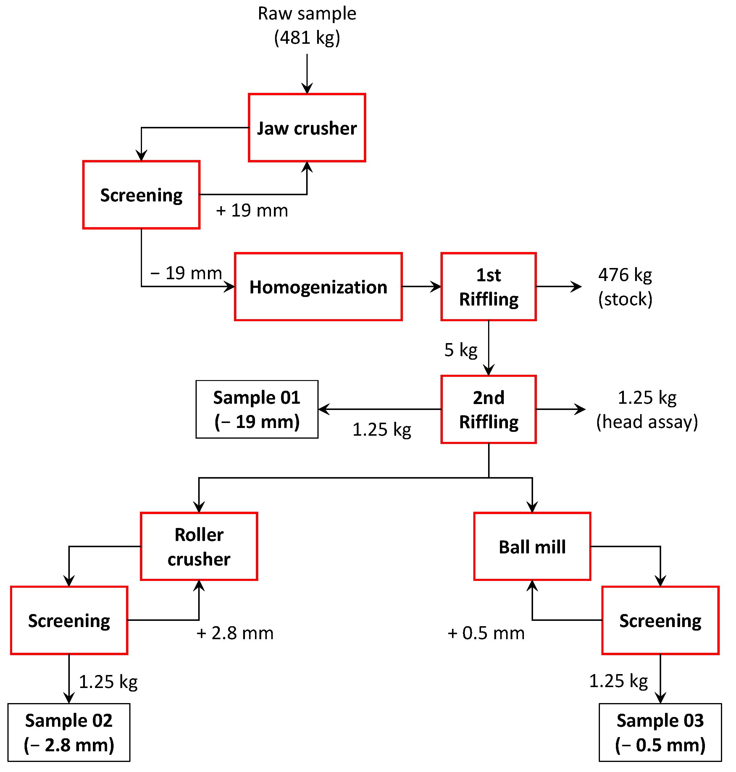
A sample of salt slag of 481 kg was obtained from a Brazilian aluminum scrap melting company consisting of the total mass of slag produced in a batch of rotary furnaces. In this batch, a charge of 14 tons of Al waste composed of a mixture of manufacturing process wastes (ingots, shavings, stampings, etc.), end-of-life products (radiators, pistons, pots, etc.), dross from primary Al production, and salt flux (NaCl and KCl, fed at a mass proportion of 3:1) was melted. The sample was collected in loco after four days of cooling at room temperature, being subsequently crushed in its entirety to −19 mm in a jaw crusher (Plangg J58, Electro Aços Plangg, Porto Alegre, Brazil).
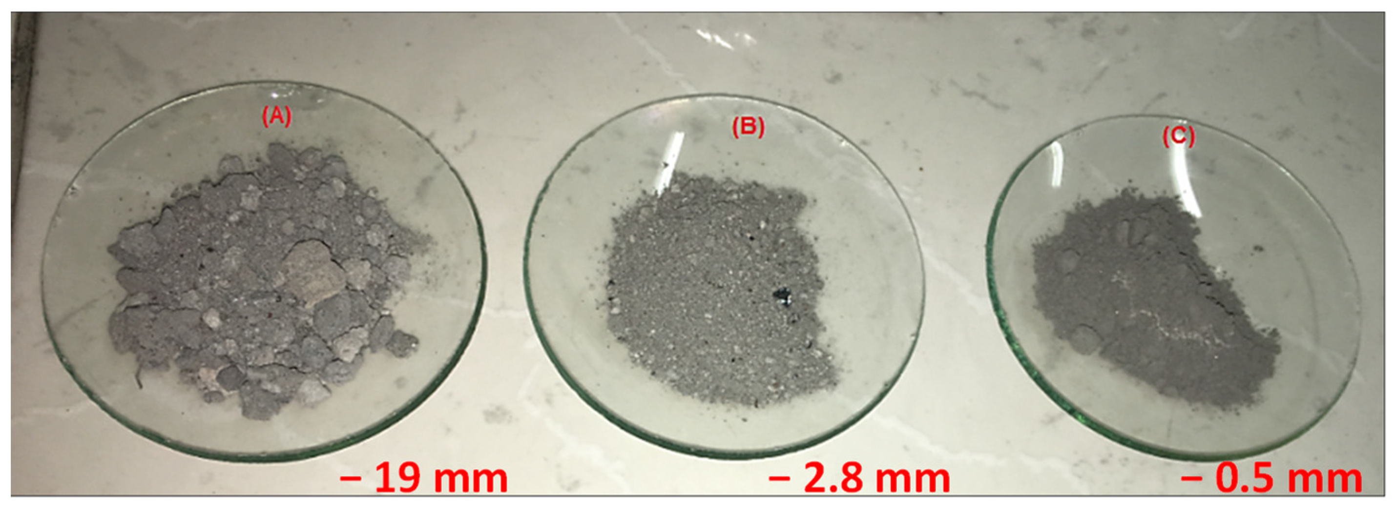
After crushing, the material was homogenized and subsampled using the elongated pile method [
22], thus producing a 5 kg subsample. From this, three aliquots of 1.25 kg each, plus one for stocking, were obtained through riffling (Jones Riffle Splitter): (A) −19 mm aliquot; (B) −2.8 mm aliquot, produced by roller crushing (Maqbrit roller crusher); and (C) −0.5 mm aliquot, produced by ceramic ball milling. Milling was conducted over 2 h in a closed circuit with a 0.5 mm aperture screen and having about 35% charge filling.
Figure 1 shows a picture of the three aliquots, while the sample preparation scheme is illustrated in
Figure 2.
2.2. Experimental Procedure
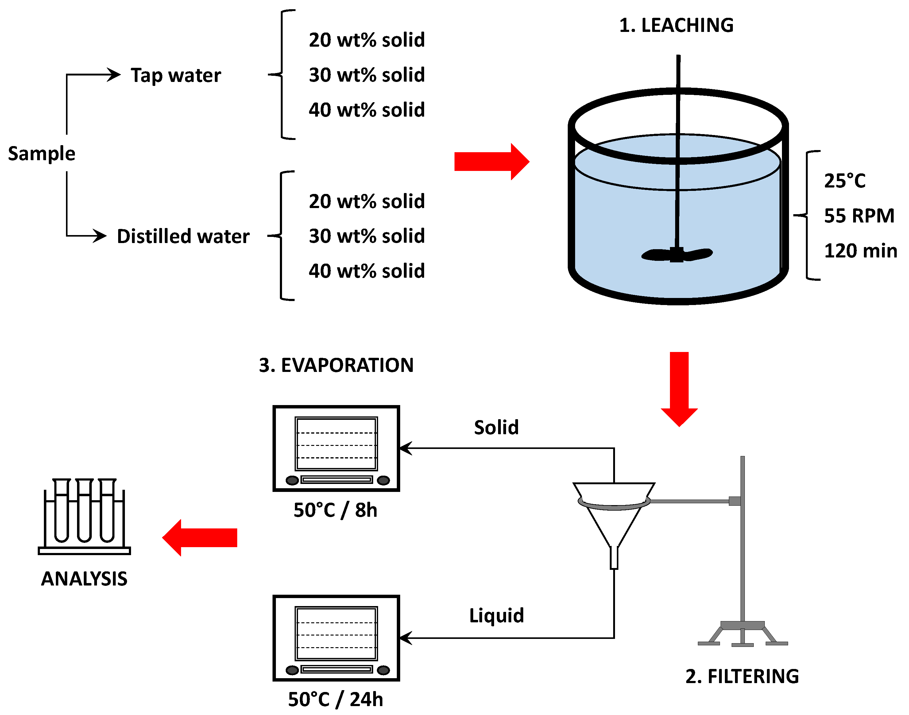
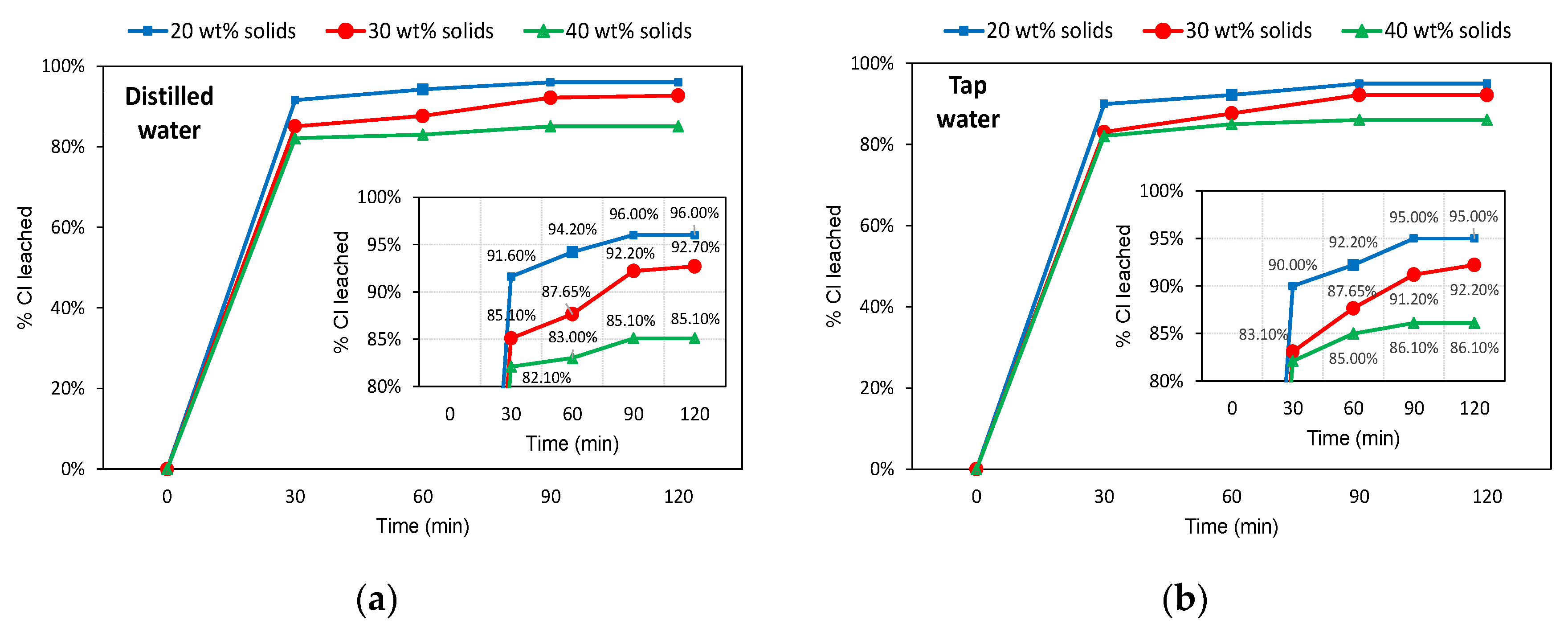
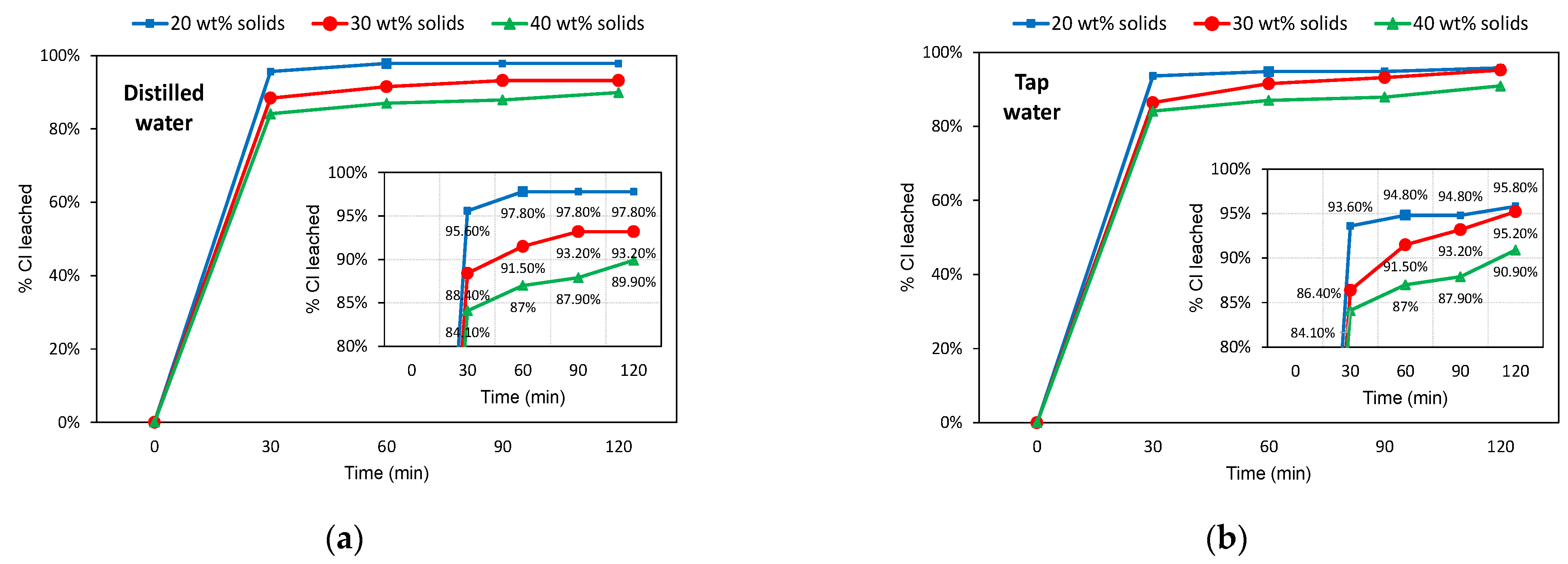
Each of the salt slag aliquots previously described was riffled to produce 70–160 g subaliquots for leaching essays. These were performed using distilled and tap water at 25 °C, pH of 6.9–7.0 (measured by pH meter) and three different solid pulp contents: 20 wt%, 30 wt%, and 40 wt% solid in the pulp. Each leaching system was agitated for 2 h at 55 RPM in a laboratory stirrer. A 1 mL solution sample was extracted every 30 min to determine the evolution of chlorine removal. Leaching tests covered 72 essays with combinations of different operational conditions (solid size, water type, solid content, and leaching time). After leaching, the material was paper-filtered, separating the leachate from the solid. The leachate was then heated in an oven at 85 °C for 24 h to guarantee the total removal of water and crystallization of the leachate. The solid fraction was heated in an oven at 50 °C for 8 h to remove humidity. All leaching tests were carried out in duplicate.
Figure 3 shows a schematic of the procedures adopted.
Leaching efficiency was assessed by the % chlorine leached, given by:
where
and
are the normalized concentrations of chloride (g/L) in leachate and non-treated slag, respectively.
The optimal leaching condition was defined as the one that resulted in the highest chlorine removal from the slag, considering the following conditions:
Leaching at the largest possible slag particle size to minimize comminution costs.
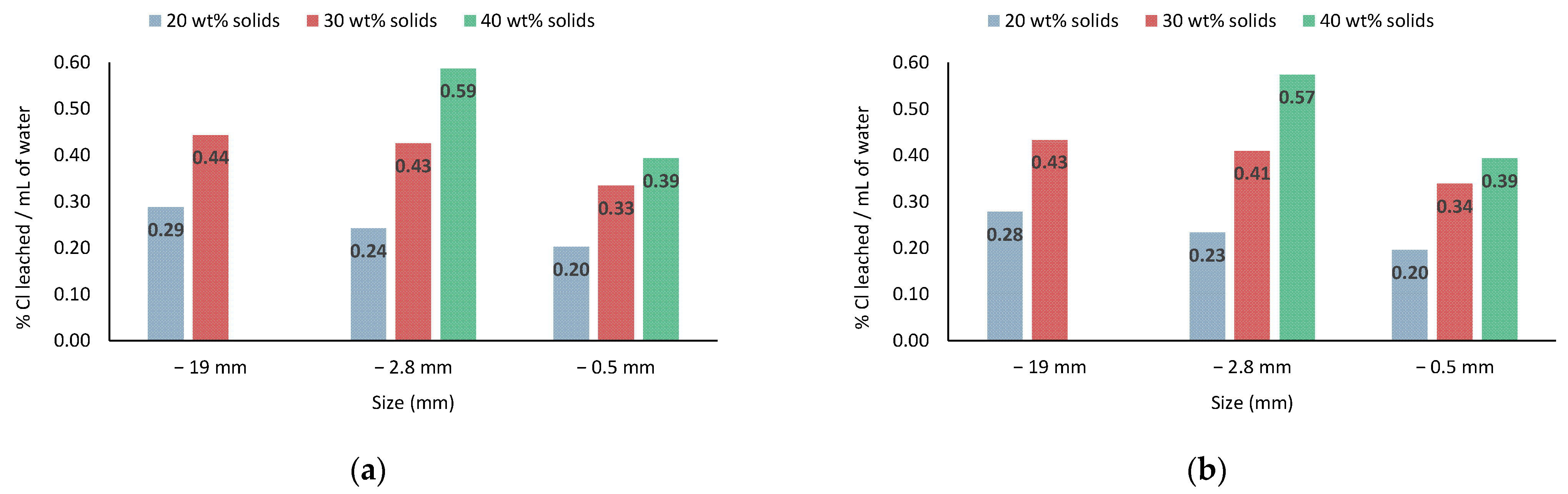
Leaching with the lowest possible water consumption (% Cl leached/mL of water).
Leaching in the shortest possible time.
Minimum leaching of 90% of chlorine, a value similar to that reported by Davies et al. [
19] and Bruckard and Woodcock [
17] for aqueous and alkaline leaching of Al salt slags.
Once the essay was defined with the best efficiency, the washed and crystallized fractions obtained were qualitatively and quantitatively analyzed.
2.3. Chemical Analysis
A chloride assay was carried out using the silver nitrate titration method (ASTM D 512-89) [
23]. This method is recommended for water where chloride content is higher than 5 mg/L, which is the case with leachate solutions from salt slags (concentrations in the range of g/L order). The head chloride assay in the raw slag sample was performed as follows: after homogenization and riffling (see
Figure 2), 1.25 kg of material was milled and pulverized in a Fritsch planetary mill (model Pulverisette 6) to a size 100% below 0.075 mm to maximize chloride liberation. The pulverized material was then riffled to obtain two portions of 50 g. Each portion was separately leached in water with a dilution ratio of 1:10 (10 wt% solid) and leaching time of 4 h, the other conditions being the same as described in
Section 2.2. The salt solution thus produced, as well as all aliquots generated in the leaching tests, were titrated with AgNO
3 (0.025 N) using K
2CrO
4 as an indicator of chloride content determination.
Elemental analysis of the head sample and the products of leaching at optimum conditions (as defined in
Section 2.2) was carried out using energy dispersive X-ray fluorescence spectrometry (ED-XRF) in a spectrometer (EDX-700 Na-U, Shimadzu, Kyoto, Japan) through the loose powder method calibrated with the Al-Cu standard. For this, the head sample and the total mass of the non-leached solids and the crystallized salts from the optimum essay were pulverized, as previously described. Then, a 1 g subsample of each (in triplicate) was placed inside the spectrometer cup. A Rhodium target was used as an X-ray source, operating up to 50 kV and 1000 mA. The detection was conducted under a vacuum atmosphere, and the results were stored in PCEDX Navi software (Shimadzu, Kyoto, Japan).
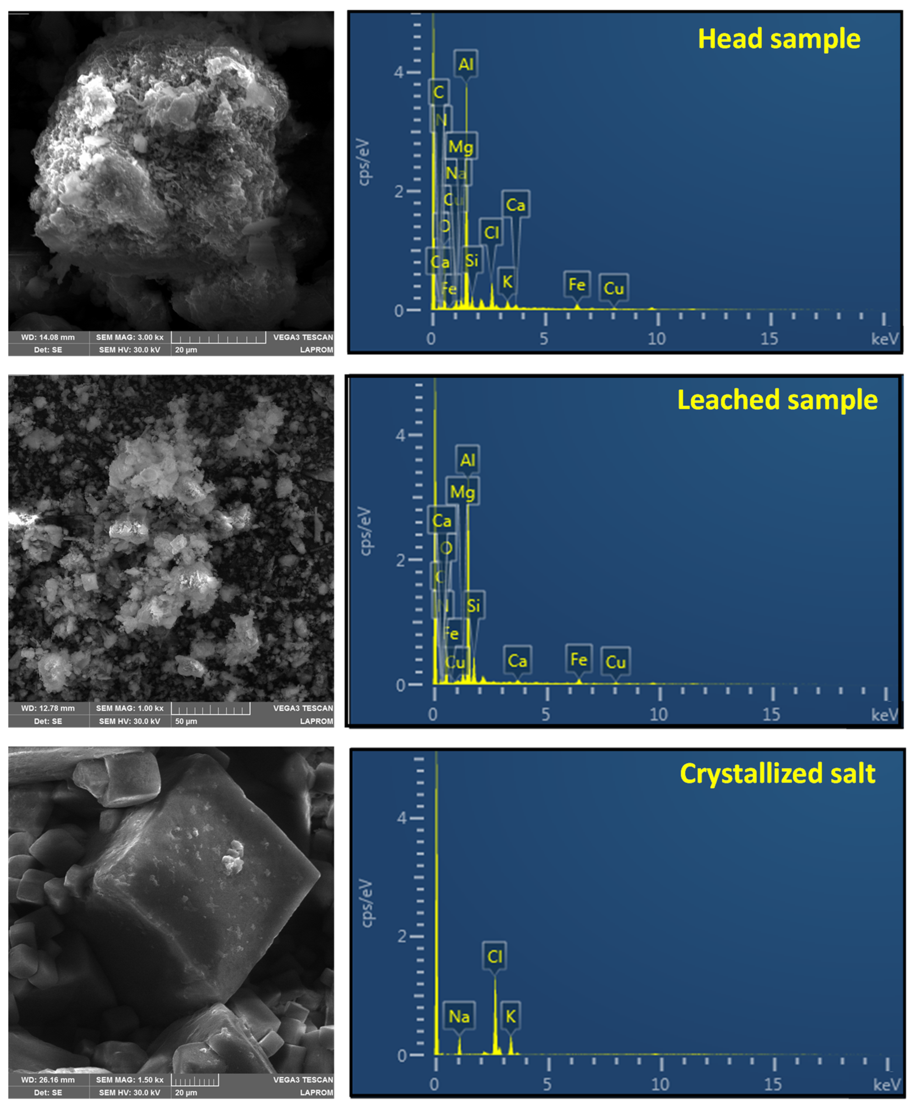
The non-leached and leached solids, and the crystallized salts from the optimum essay were also submitted for further analysis. Changes in microstructure were evaluated through scanning electron microscopy (SEM) using a Tescan microscope model C3, coupled with an Oxford energy dispersive spectrometer (EDS).
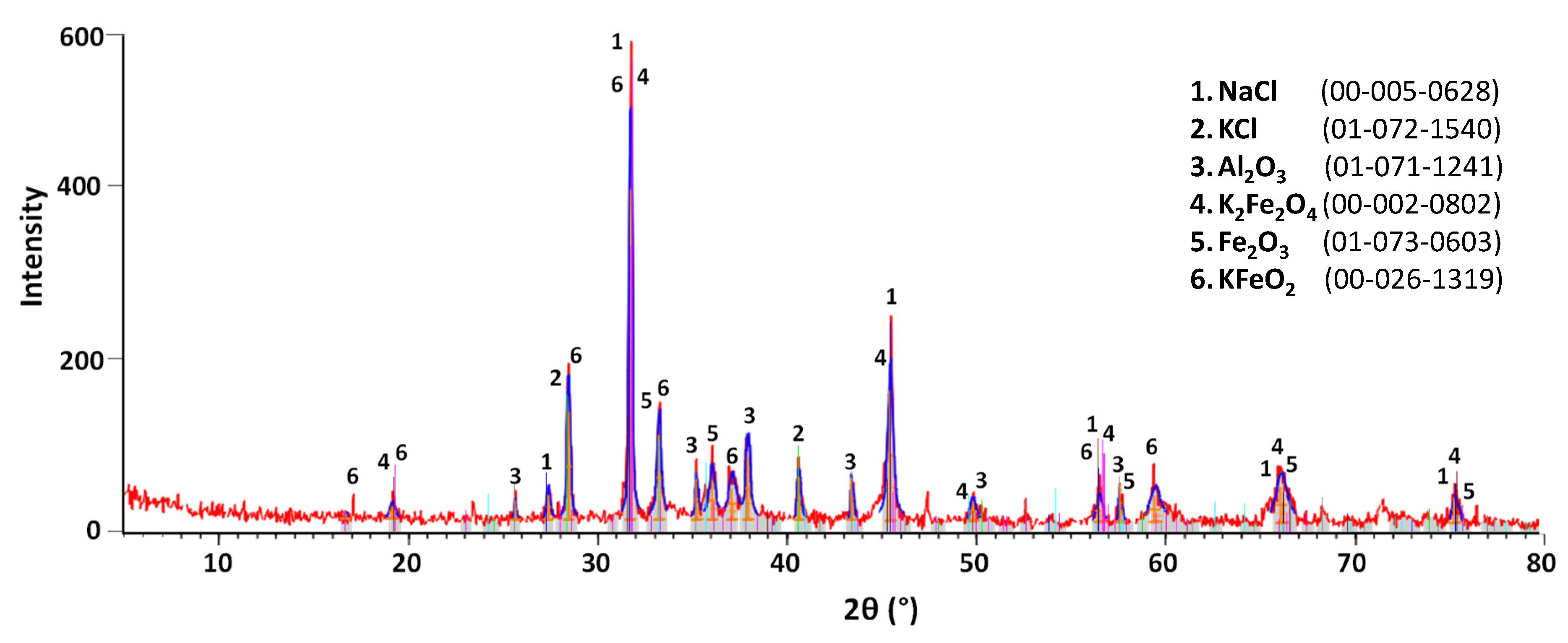
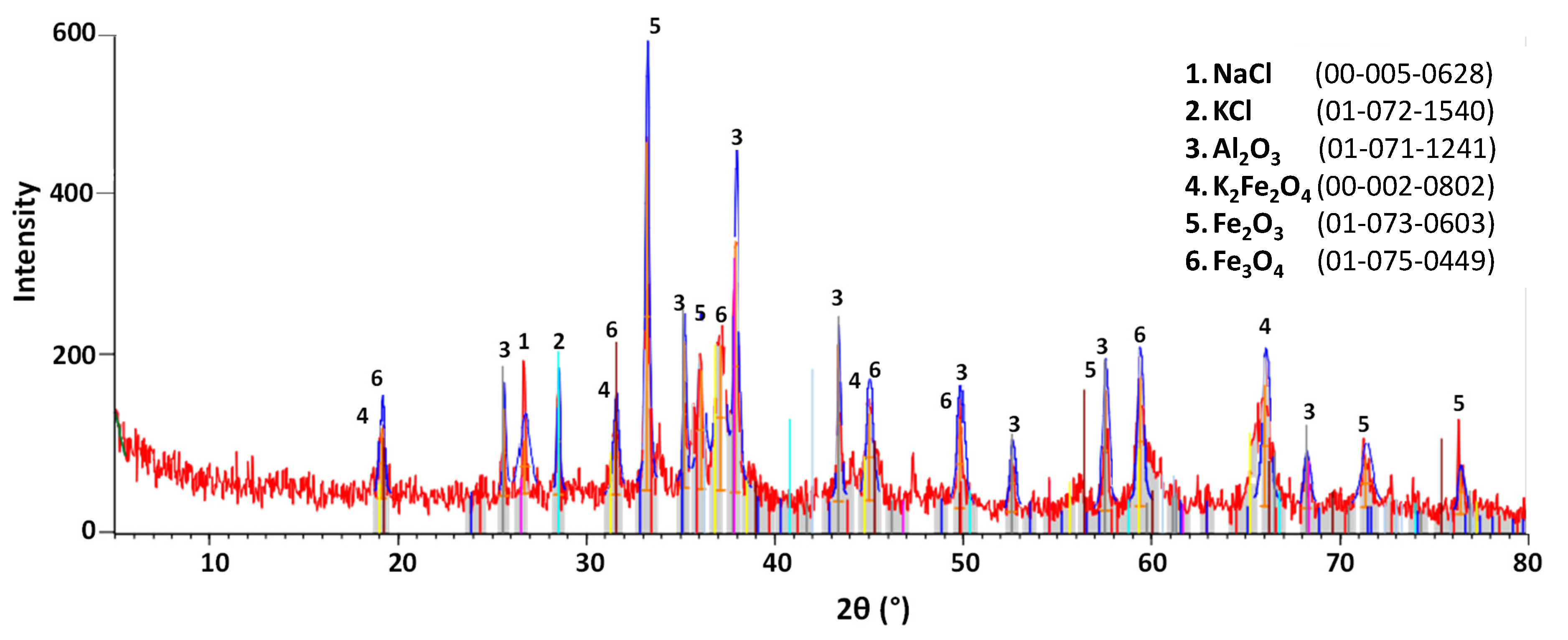
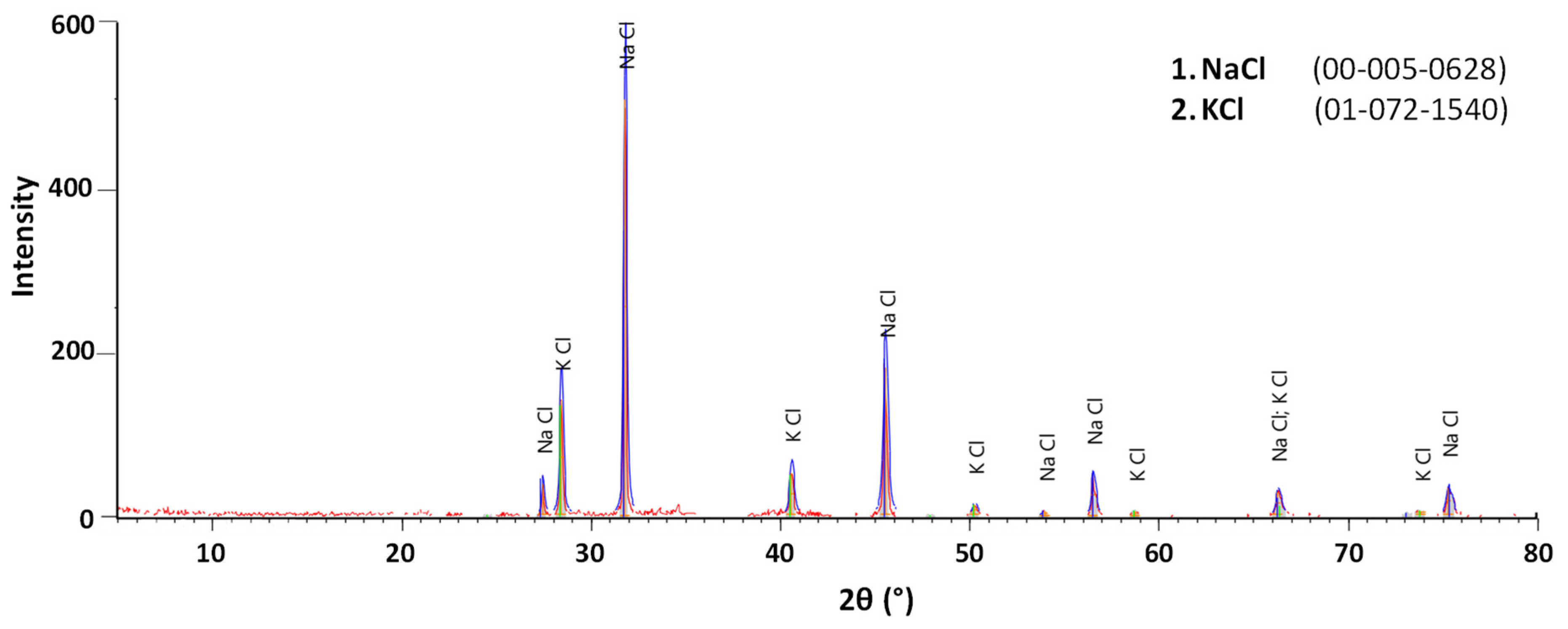
X-ray diffraction data sets were collected from 5 to 80° 2θ at 0.05°/s on a Siemens Bruker AXS D-5000 diffractometer using Cu radiation (λ = 1.5406 Å), operating at 40 kV and 30 mA in the primary beam. A graphite monochromator, a 1° anti-scatter slit, and a 0.2 mm receiving slit were used on the diffracted beam. Finally, sodium (Na+) and potassium (K+) concentrations were assayed in triplicate by flame atomic absorption spectrometry (FAAS) in Perkin-Elmer A Analyst 200 equipment using a Lumina Hollow Cathode Lamp.
4. Further Discussion
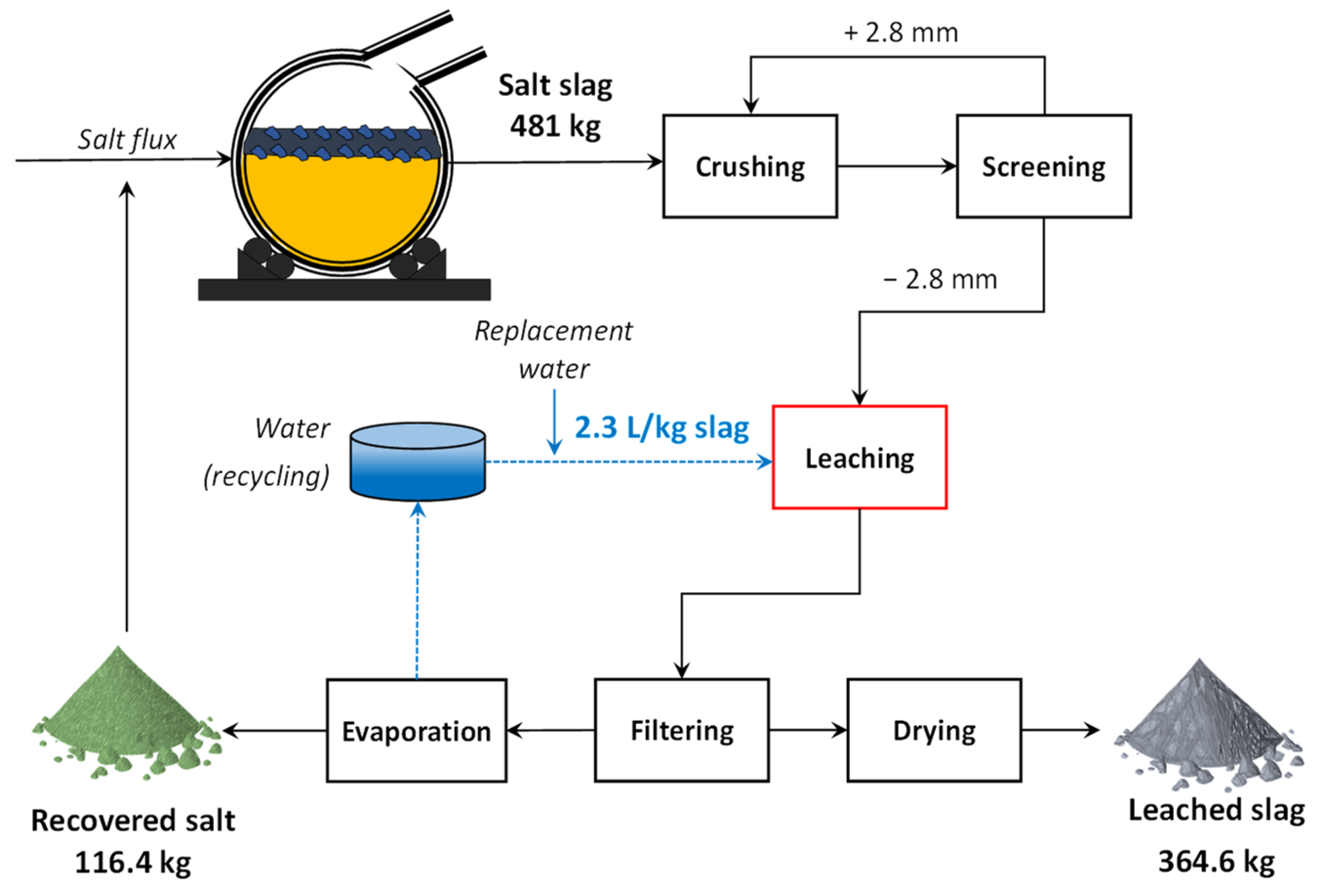
Figure 12 shows a preliminary processing flowsheet and mass balance for salt slag treatment, considering the optimum leaching conditions. In this case, 24.2% of the slag mass was dissolved during leaching, resulting in about 365 kg of treated slag for 481 kg of raw slag produced in the furnace batch. Based on this overall mass balance, material balances were also performed for each major element to calculate the balance accuracy error (residual mass divided by the total mass of the element) and thus check the accuracy of elemental analysis. Considering the ED-XRF analysis data, balance errors ranged from + 1.29% for Si to about −8% for K, where the positive (+) and negative (−) signals mean a surplus and a shortage of elemental mass, respectively. On the other hand, balances carried out for titration/FAAS analysis data (Cl, Na, and K, only) exhibited a maximum error of + 0.15% for K, suggesting an accuracy higher than that of ED-XRF analysis. Thus, the results from titration and FAAS analysis were adopted to estimate the performance indexes (purity and recovery) of the salt recycling process.
The purity and overall recovery of salts were 90% and 92%, respectively, with a NaCl:KCl proportion of 4.3:1, allowing its effective recycling with a few additions of KCl to adjust the salt flux proportion adopted by the recycler (NaCl:KCl of 3:1). It is worth noting that despite their low individual concentrations, some impurities detected in the recovered salt may slightly decrease its capacity to form stable chlorides with contaminants (such as Mg and Zn) during its reuse as flux, since the salt could already be partially saturated with one or more of these elements. Analyzing it, however, is beyond the scope of this study. The water demand for leaching with 30 wt% solids in pulp would be 2.3 L/kg of fed slag. This value could be reduced to 1.5 L/kg of slag if 40 wt% solids in pulp were used, but at the cost of a lower leaching efficiency, as discussed in
Section 3.2.
The crushing operation indicated in the flowsheet in
Figure 12 can mean either the two-stage crushing used in the current study or another arrangement. The salt slag sampled was easily fragmented, so perhaps a single roller crushing operation in close circuit with screening could be enough to achieve the used particle size (−2.8 mm). Gravity sedimentation in tanks could also be used for the solid-liquid separation of leachate and solid residue after leaching, as mentioned by Shinzato [
16], although its efficiency would arguably be below filtration systems. Most importantly, minimizing the costs of drying and evaporation is a pivotal point for improving the economic viability of salt slag treatment. When possible, the use of heat recovery systems can be an efficient strategy for decreasing costs, as the sensible heat of flue gases produced in furnaces could be redirected to those operations, thus increasing the thermal efficiency of the process. Solar dry/evaporation ponds could also be an option, as suggested by Bruckard and Woodcook [
17].
5. Conclusions
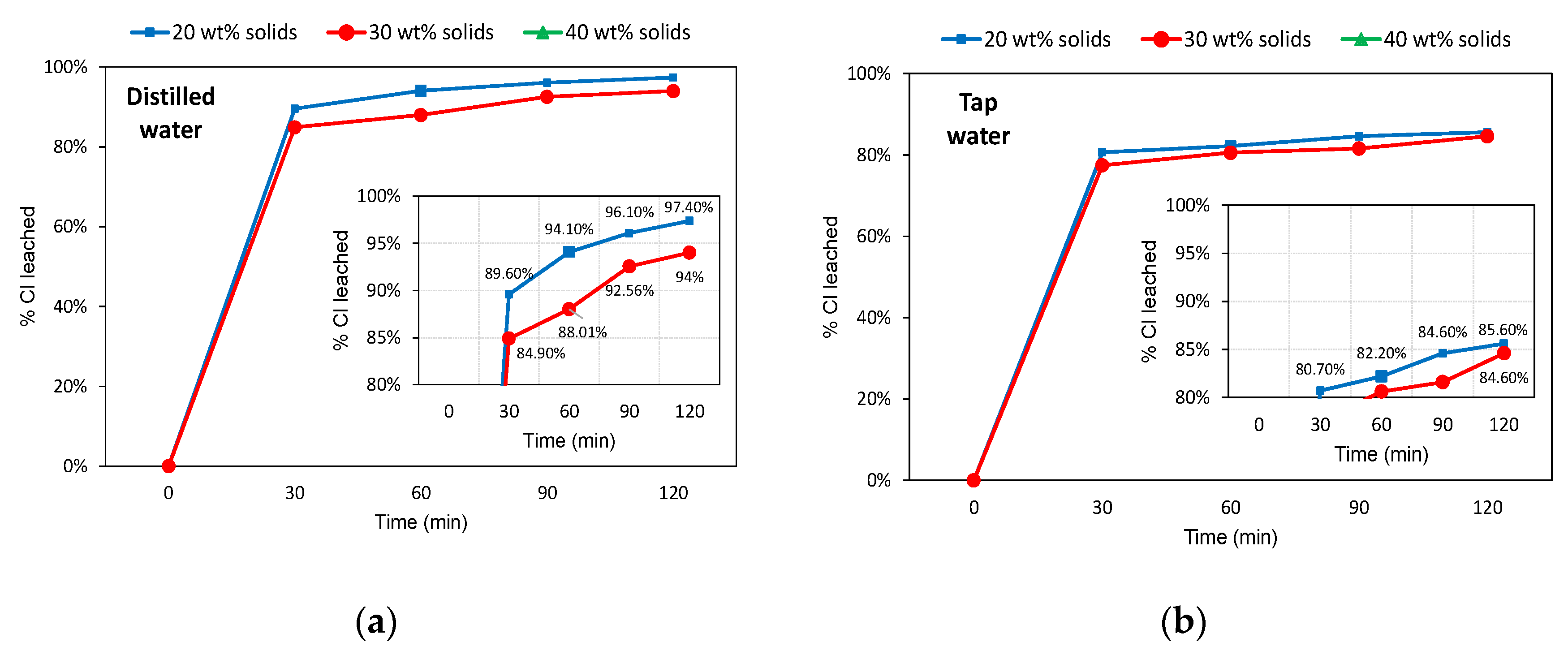
In this study, we focus on optimizing the water leaching of chlorides from Al salt slag and testing practicable operational conditions. Leaching with tap water at 25 °C made it possible to dissolve more than 92% of the chlorides contained in the raw slag under the optimum leaching conditions: particle size below 2.8 mm, 30 wt% of solids in pulp, and leaching time of 90 min.
The leached slag consisted mainly of Al (predominantly as Al2O3), Si, Fe, Ca, and minor elements (Mg, Mn, Ti, and Zn), with less than 2.5% salts after leaching (compared to about 24% before it), and the recovered salt obtained after evaporation consisted of about 90% NaCl and KCl, with the potential to be re-mixed to the salt flux fed to the furnace. The possibility of minimizing water demand by performing leaching with 40 wt% solids in pulp was also presented, although this resulted in a lowering of leaching efficiency.
Finally, the study provides a framework for future studies to assess the performance of other operations that can possibly be used for salt slag treatment. Future work should focus on strategies to optimize water usage, such as the use of heat recovery systems associated with drying and evaporation steps, as well as further treatment of the leached fraction for its reuse and recycling.


 ,
, 


