1. Introduction
Permanent magnet materials are important for industry, military, and information technology [
1,
2,
3,
4]. At present, in an environment where green and clean energy is promoted, the demand for permanent magnet materials in the fields of wind power, electric vehicles, electric motors, robots, and aerospace is continuously increasing [
5]. Among the permanent magnets, the demand for Nd-Fe-B increased the most, reaching 2.1×10
4 t production in 2020. However, after 2011, the price of rare earth soared due to fluctuations in prices [
1]. At the same time, Ce-containing dual-main phase (DMP) Nd-Fe-B magnets emerged and became popular due to their balanced utilization of high-abundance rare earth elements [
6]. DMP magnets are made by adding Ce-Fe-B during the preparation of Nd-Fe-B magnets to form magnets with both Nd-Fe-B and Ce-Fe-B main phases, and they have excellent magnetic properties compared to single main phase Nd-Fe-B magnets [
7,
8].
As the temperature increases, all magnets inevitably face the problem of irreversible demagnetization, and the above means only alleviating the problem to a certain extent. After the high temperature demagnetization of the magnet, it still has enough magnetic properties for use. The ideal magnet should have a high magnetic energy product and a square demagnetization curve, which undoubtedly describes Nd-Fe-B magnets. However, the Curie temperature of 315 °C limits its usable condition, which has to be lower than 80 °C (N grade); otherwise, irreversible demagnetization will occur. Although the coercivity is increased by adding heavy rare earth elements such as Dy and Tb, and although the Curie temperature is increased by adding Co, the maximum service temperature is not more than 240 °C (AH grade) [
3]. When the Nd-Fe-B magnet rises from 20 °C to 100 °C, the magnetic energy product will decrease by half, and the motor power will decrease [
9], which will cause a waste of magnetic energy.
Because the resistivity of rare earth permanent magnets is very small, the eddy current generated in them is the main factor for the heating of magnets. Reducing the eddy current loss in magnets and thus reducing the temperature of magnets during operation is a problem that needs to be considered. Through the optimization of motor structure designs, although a certain effect has been achieved [
9,
10,
11], the magnet resistivity is often used as a fixed value, so the optimization results are not satisfactory. In addition to optimizing the design of the motor structure, Aoyama [
12] noted that increasing the resistivity of the magnet can also effectively reduce the eddy current loss. Considering the skin effect of the eddy current and the insulation of the main phase grains or raw material particles in the magnet, the electron transport in the magnet can be reduced by the heat source, and the resistivity can be increased. Thus, the working temperature of the magnet can be decreased. Gabay [
13] introduced CaS for insulation and isolation, and it was found that adding sulfur (phosphorus) compounds would form NdS, which would reduce the metallurgical bonding of the cladding layer. Although the introduction of SiO
2 increases the resistivity to a certain extent, Nd will combine with O to form NdO, resulting in the loss of the Nd-rich phase and the reduction of magnetic properties [
14]. Fluoride is suitable for addition to permanent magnet materials because of its inertia. The addition of NdF increased the magnetic resistivity by 200% [
15]. Komuro et al. [
16] prepared a magnet with a fluoride coating with a resistivity of 1.4 mΩ·mm. The surface resistivity of the magnet increased by 10 times, and the rotor temperature decreased by 50%. Although these works have made some progress, some problems still occur. In the above methods, most of the materials involved are inorganic compounds. In the process of magnet insulation and coating, these inorganic compounds cannot deform with the magnet; thus, spalling occurs during the deformation process of the magnet, which cannot effectively isolate the magnet. In addition, it is often necessary to complete the coating process with the help of liquid re-rich phase flow. The participation of the rare-earth rich phase in the coating will not only reduce the insulating ability of the coating layer but also cause the loss of the rare-earth rich phase and reduce the magnetic properties.
The method of adding insulating materials and the form of insulating materials play an important role in the resistivity of composite materials. McLachlan [
17] gave the general effective media equation and described the different wetting and coating conditions between the conductive phase and the insulating phase. For calculating the resistivity of composite materials with continuous isolation layers:
ρm is the resistivity of the composite, ρh is the resistivity of the low-conductivity phase, Φ is the volume fraction of the high-conductivity phase, and mΦ is the exponent for randomly oriented high-conductivity ellipsoids.
Depending on the value range of mΦ, a thin layer of insulation distributed continuously helps to isolate electron transport between adjacent particles, thus increasing the resistivity of the composite magnet. As seen from the metal binary phase diagram, most of the crystalline compound insulating materials have very high melting points, which cannot follow the deformation of the magnet during the particle coating process. Moreover, spalling occurs during the deformation process. At the same time, liquid re-rich phase flow is often needed to complete the coating process. The isolation layer formed by these crystalline compounds is still dispersed rather than continued under the non-wetting or intermediate wetting case discussed for the general effective media equation.
In this work, to overcome the shortcomings of the insulating layer, we designed a composite magnet doped with amorphous materials. In contrast to crystalline materials, amorphous materials, which can be deformed well with magnetic powder, will exhibit viscous flow with an increasing temperature. Through the systematic study of magnets with amorphous glass fibers, it is verified that this design can significantly improve the resistivity of the magnets and facilitate the preparation of magnets with oriented textures. The new design idea provides a new way to develop high-resistivity rare earth permanent magnets with oriented textures.
4. Discussion
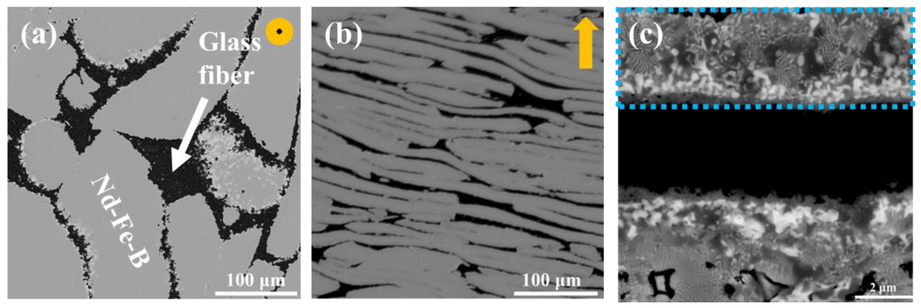
Figure 6a shows the microstructure of the magnet without glass fiber. The gray part in the image is the main Nd-Fe-B phase, and the highlight is the rare-earth rich phase between Nd-Fe-B layers. Nd-Fe-B particles change into sheets due to endure along the direction of pressure (arrow in
Figure 6a).
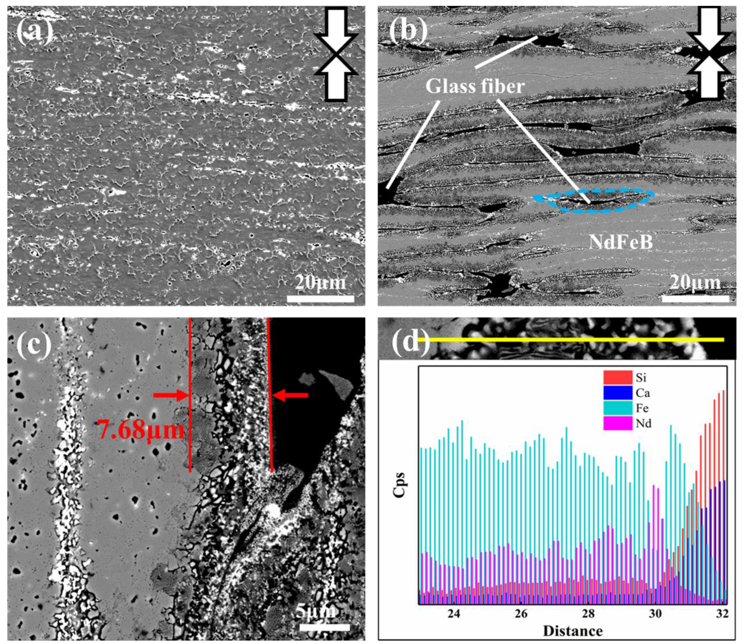
Figure 6b shows the microstructure of the magnet with 10wt% glass fiber added. The black part is the glass fiber, and the gray part is the Nd-Fe-B main phase. The dark area between the glass fiber and the Nd-Fe-B sheet is the transition layer (dashed blue area in the image).
EDS line scanning was carried out for the distribution of interface elements between magnetic powder and glass fiber, and the results are drawn in
Figure 6c,d. The Fe element kept a high element concentration in the Nd-Fe-B phase, and the concentration decreases step-by-step as the distance approaches the magnetic powder interface. The variation tendency of Nd element concentration is consistent with that of the Fe element. Nevertheless, the mutation occurs in eutectoid tissue, where the Nd element concentration is more than that of Fe element at this mutation position. The Si element, on the contrary, whose concentration emerges gradually, decreases from glass fiber to the Nd-Fe-B phase until the Nd element is in the position of the mutation. The Ca element concentration is almost the same as Si element concentration, with only a small change, simultaneously, and simultaneously disappeared until the Nd element reached the position of the mutation.
According to energy spectrum analysis, the Si element is present in all interface reaction regions, indicating that the Si element is capable of a wide range of diffusion phenomena. Xu et al. [
18] investigated the corrosion of Ni-based alloys with various elements added by molten glass and discovered that the metal elements in the alloy could reduce the Si element from glass. Its reduction reaction is:
The Fe element is enriched at the forefront of the interfacial reaction, indicating that it was the first to participate in the reaction process. In their studies on the interface reaction between Kovar alloy/Invar alloy and glass, Luo et al. [
19] and Khachatryan et al. [
20] discovered that FeO, Fe
3O
4, and Fe
2O
3 can be formed sequentially as the O concentration changes. These products can react with the glass indefinitely, eventually forming the Fe
2SiO
4 phase. As a result, Fe oxidation occurs because:
Finally, the interface reaction process at the forefront of the interface between magnetic particle and glass fiber should begin with the contact of the surface of the magnetic particle and glass fiber, and the elements on both sides should begin to diffuse. Because the Fe element is the first to participate in the reaction, FeO, Fe
3O
4, and Fe
2O
3 are produced sequentially. Furthermore, the CaFe(Si
2O
6) phase is formed in the glass fiber by combining with the CaO, and the reduced Si element diffuses into the magnetic particles. The precise equation is:
It should be pointed out that in this reaction, the O element will be released, so the O element will also diffuse into the interior of the magnetic particle.
As previously stated, the O element was released during the reaction process. Because of the higher activity of RE elements, the Nd element began to combine with the O element at this point to form the Nd
2O
3 RE-rich phase. This reaction consumes the released O element, and the Fe element that has diffused with it must be diffused further into the glass fiber to keep the reaction going. This explains why there is a mutation in the concentration of Nd elements in this region. The precise equation is:
In the preparation process of the thermal deformation magnet, the glass fiber was added to the magnetic particle interface reaction, forming a variety of reaction products, and through analysis of the three sections, there was no doubt that the interface reaction between the magnetic particle and the glass fiber was controlled by the diffusion process. At the forefront of the interface, the Fe element substituted the Si element in the glass fiber, forming a series of oxides, for instance, that eventually reacted with each other and formed the CaFe(Si2O6) phase. Analysis of the energy spectrum near the interface indicates that the concentration of the Nd element increases abnormally before the Fe-rich zone, and the Nd element can hardly diffuse through the CaFe(Si2O6) phase, just like a wall blocking the diffusion direction of the RE element. Similarly, the Ca element does not spread beyond the Fe-rich zone into the interior of the magnetic powder. It is inferred that the glass fiber that was added has an important role to form a “Fe-rich wall”, which can effectively block the “leakage” of RE elements from the main-phase grains. This phenomenon can be applied in the process of the diffusion of heavy RE elements in the magnet, or to regulate the diffusion of heavy RE elements into the magnet.
In the above process, CaO and SiO2 decomposed from glass fiber will be pushed into the narrow grain boundary with the softening flow of glass fiber, more fully isolating the ferromagnetic coupling between the main grains, and oxides have a good insulation effect, so the diffusion reaction between the glass fiber and magnetic powder can lead to an increase in resistivity.
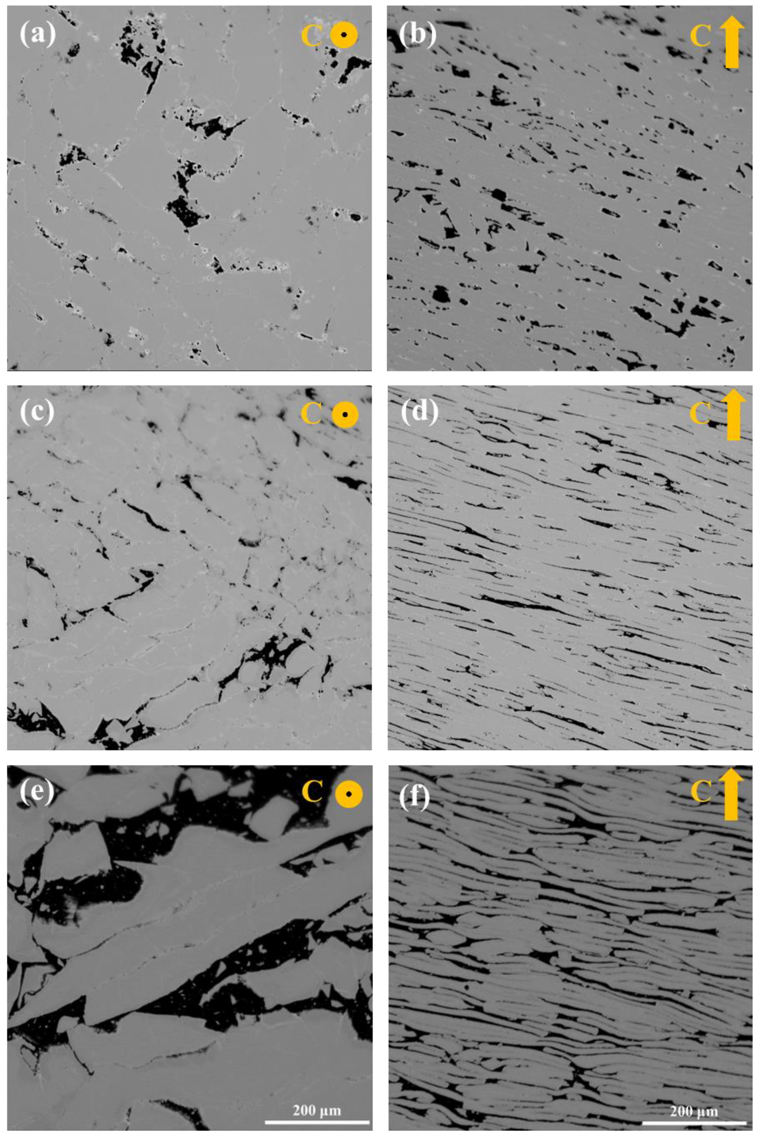
The structure of the above experimental magnets is shown in
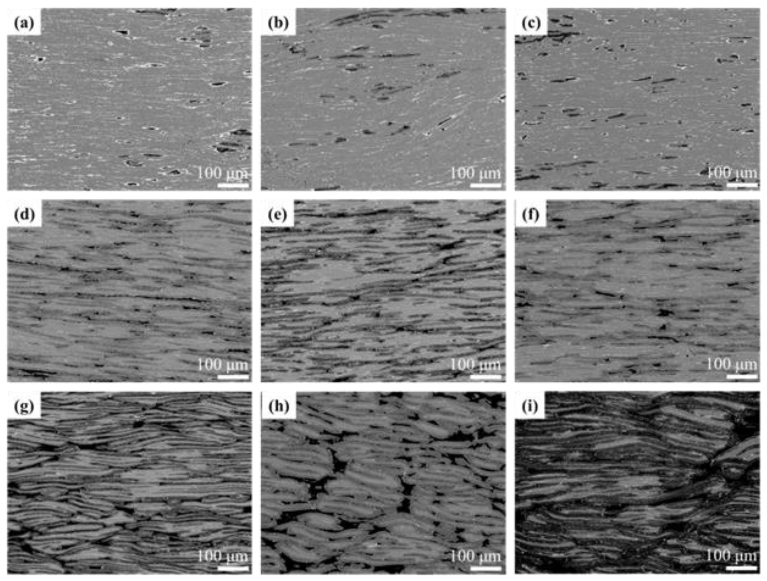
Figure 3. The black area is glass fiber, the bright white area is the rare-earth rich phase precipitated during the preparation of the magnets, and the gray part is the Nd-Fe-B phase. With the increase in glass fiber addition, the distribution of black glass fiber gradually changed from sporadic distribution to continuous distribution. According to the design of the orthogonal experiment,
Figure 7a–c show the morphology of glass fiber with 2 wt.% addition. Due to the small amount of addition, glass fiber is less distributed among Nd-Fe-B grain lamellas and scattered in the matrix structure.
Figure 7d–f show the morphology of the glass fiber with the additional amount of 5 wt.%. It can be seen that with the increase in the addition, the distribution of the glass fiber between Nd-Fe-B laminates increases, and, thus, the resistivity of the magnet increases. However, it can be seen that due to the insufficient addition, there is still a large area uncoated between the Nd-Fe-B lamellae. When the addition amount reaches 10 wt.%, as shown in
Figure 7g–i, the glass fiber has formed a relatively complete coating layer, and so the resistivity of this group of samples is, relatively, the highest.
By comparing different deformation temperatures,
Figure 7a,f,h is 850 °C. Due to the low temperature, the magnetic particle deformation degree is small, the glass fiber deformation degree is also insufficient, and the glass fiber aggregates in the magnet. With the increase in deformation temperature, that is,
Figure 7b,d,i are the morphologies at 870 °C, and
Figure 7c,e,g are the morphologies at 890 °C. The analysis shows that the deformation of the grain increases gradually, while the aggregation of the glass fiber decreases, indicating that the glass fiber is also deformed in the process of thermal deformation and is squeezed into the grains to form the coating layer. Compared with 9 groups of experimental samples, sample no. 7 (
Figure 7g) has the best coating effect, a large deformation degree, uniform distribution of tissue, and, therefore, the highest resistivity.
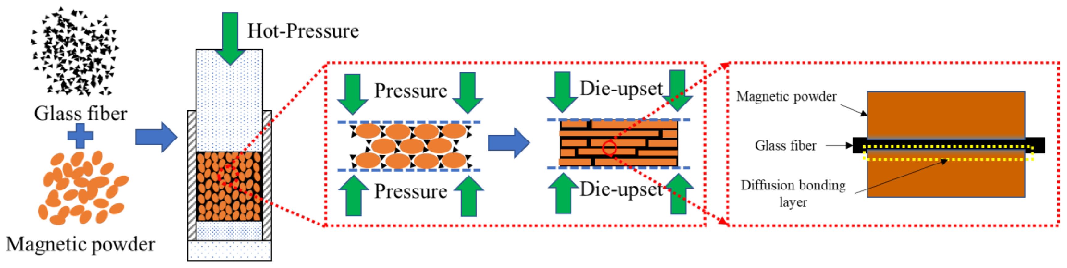
Figure 8 shows the schematic of the preparation process of the magnets with glass fiber. Based on the microstructure, glass fibers are fully embedded around the magnetic particles and maintain the original particle shape during the hot-pressed process. After being hot-deformed, the magnetic flakes change into thin sheets and distribute in parallel to the direction of pressure. The glass fiber particles aggregate with each other and form a thin sheet distributed among the magnetic sheets, effectively separating the magnetic flakes. Moreover, there is a transitional layer at the contact surface between the glass fiber and the magnetic sheets, indicating that there is a mutual diffusion of elements between the two, forming a new phase. Therefore, the magnetic flakes and the glass fiber can be firmly bonded together, thus effectively avoiding the isolation failure caused by peeling, which is beneficial for improving resistivity.
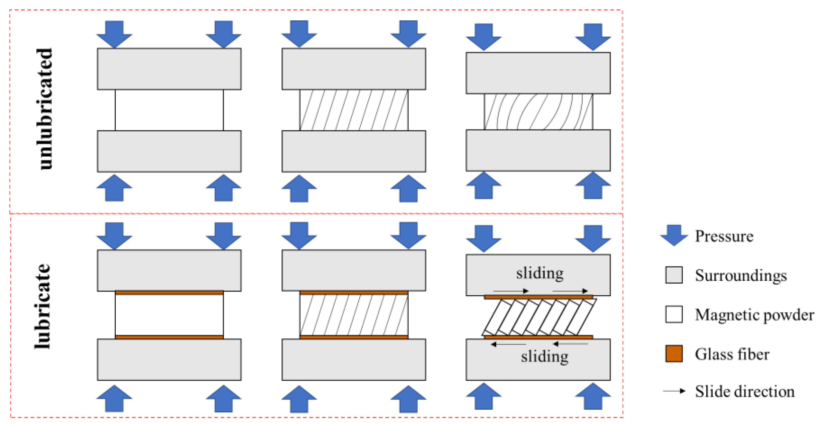
With increasing additions of the glass fiber, the intensity of the main-phase peaks decreases; nevertheless, the intensity of the main-phase peak (006) is abnormal in
Figure 4h. There is no doubt that the orientation degree (I(006)/I(105)) increased dramatically, which means that the orientation of the magnet is improved. This is due to the glass fiber collaborative deformation with Nd-Fe-B powders during the hot deformation process. According to Zhu’s theory [
21], the grains of magnetic powders slide and rotate in the thermorheological process. Softened glass fiber acts as a lubricant in the gaps of the Nd-Fe-B powders, and the grains of the Nd-Fe-B powders are more likely to slide and rotate under the action of external force, as shown in
Figure 9.
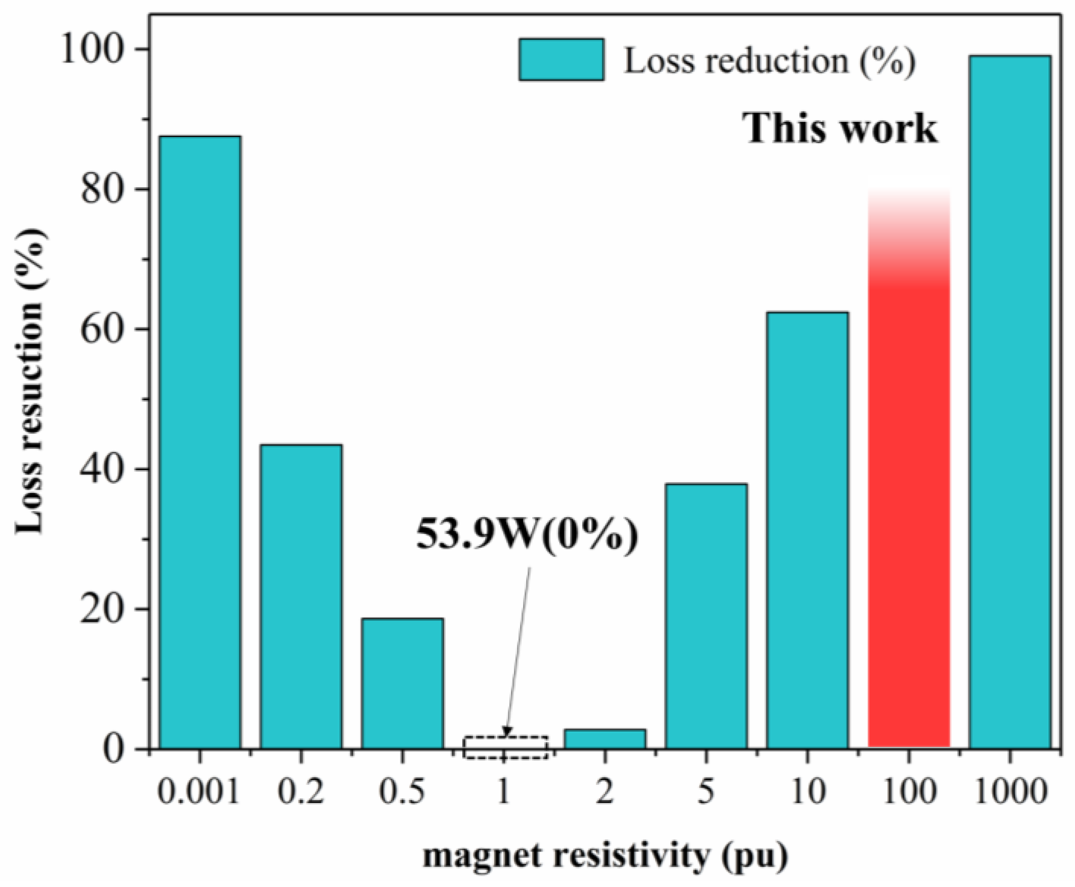
In contrast to other insulating materials, adding amorphous glass fiber to the magnet greatly improves the resistivity. Shen [
22] calculated and simulated the relationship between eddy current loss and the resistivity of magnets by FEA models. As shown in
Figure 10, the relationship between the resistivity of a magnet and the reduction of the eddy current losses in magnets was shown. It should be pointed out that
pu (per unit) is the resistivity of sintered Sm
2Co
17 magnets (8.503 × 10
−2 mΩ·cm). The resistivity of the magnet prepared in this work is 85 times that of the one in
Figure 10. This means that eddy current losses are reduced by at least two thirds, relative to the magnets that have not been treated with high resistivity. Therefore, the addition of the amorphous glass fiber magnet can reduce eddy current loss very effectively.


