1. Introduction
Mechanical joining technologies, such as clinching, clinch-riveting and self-piercing riveting have been proved effective for joining lightweight materials with high strength. Lightweight constructions have gained considerable interest in recent years, because of their economic and environmental properties. Among the mechanical joining methods, the clinching technology has been developed rapidly. Unlike clinching, clinch-riveting and self-piercing riveting require a rivet, which may increase the weight of the joint. However, a higher forming load is necessary [
1,
2]. Clinching has been used on an industrial scale for over 30 years and has been successfully applied to a wide variety of materials and material combinations. Clinching is commonly utilized in car body production [
3], building components [
4], even in electrical industries. It is a cold joining process of sheets by local hemming with a punch and die. The material between the punch and die is forced into a radial flow to form the undercut. This method belongs among forming joining technologies. The joined sheets are deformed locally by creating a mechanical interlock. It is used for joining thin sheets from 0.5 to 4 mm single sheet in thickness, up to a total joint thickness of about 20 mm. The load-bearing capacity of the clinched joint mainly depends on the geometrical parameters of the joint profile, which is mainly influenced by process parameters and the clinching die [
5,
6,
7,
8].
It is a great advantage that clinching does not generate any thermal stress that would affect the joined materials. The clinching is a low energy process and does not destroy coating or produce fumes such as occur with resistance spot welding. What is more, it does not require a pre-drilled hole and it is not necessary to specially prepare the surfaces of the joined materials. This highly flexible method can therefore be employed for joining a wide range of materials. Previous research focused on joining steels and aluminum alloys; however, recent experiments have also dealt with copper, magnesium, titanium alloys [
9,
10], carbon fiber-reinforced plastics [
11], hybrid metal-plastic polymers [
12,
13] as well as metal-reinforced plastics [
14,
15]. When joining the abovementioned materials by this method, there may occur a problem with limited metal formability. This can be avoided by pre-heating the materials or by changing the material flow to prevent the formation of cracks [
16].
A number of experimental studies have been carried out to understand the forming process of clinched joints. These experiments usually take a long time to perform and they are quite expensive, especially when tool geometry or material properties should be modified. For this reason, the Finite Element Method (FEM) is frequently utilized [
17,
18,
19]. The information that can be obtained from the simulation of the clinching process includes the following: material flow, distribution of strains and stresses, distribution of pressure at the interference of the die and material, the influence of friction, and filling of the die gap with the joined materials [
19].
Primarily, recent numerical studies of clinching have focused on fastening procedures of the joints [
4,
20]. Regarding the modeling strategies, a significant majority of the investigations performed 2D axial-symmetric simulations using dynamic explicit or static implicit Finite Element (FE) techniques for the numerical treatment [
21,
22,
23]. The dimensional reduction of the analysis from 3D to 2D can be accomplished under certain circumstances, particularly with regard to the mechanical behavior of the sheet-isotropic material behavior [
24]. A finite element procedure with an automatic remeshing technique was developed by Hamel et al. and Oudjene et al. [
25,
26] to simulate the clinching process. The resolution of an updated Lagrangian formulation is based on a static explicit approach. Comparative studies of clinching tools for joining the high-strength sheet metals of various thicknesses were conducted by Varis [
23,
27]. Numerical investigations were utilized in the study into the strength and energy absorption of the clinched joints [
28,
29,
30]. A study into the evaluation of the material flow in the extendable die using FE simulation was conducted by Lambiase et al. [
13,
31,
32]. Yang et al. [
33] developed an ANSYS FE model for simulating the clinching process on the base of the elastic-plastic FE theory. The influences of the die parameters and combinations of sheets thickness on the interlock and neck thickness were investigated. Finite element simulations were also carried out by Mori et al. [
34] for clinching high-strength steel and aluminum alloy sheets. The experimental research proved that the FE-based advanced calculation techniques can also serve as tools for predicting coating behavior [
35,
36].
High-strength steel sheets have a different hardening system than low-carbon steel sheets during the forming process. The usage of high-strength steels imposes higher requirements on the tool’s surfaces, as it significantly increases tool wear. The intensity of surface wear on the active parts of the forming tool can be influenced by the choice of tool material, its heat treatment or chemical surface treatment. There are numerous surface treatments, including currently commonly used physical vapour deposition (PVD) coatings [
37,
38,
39,
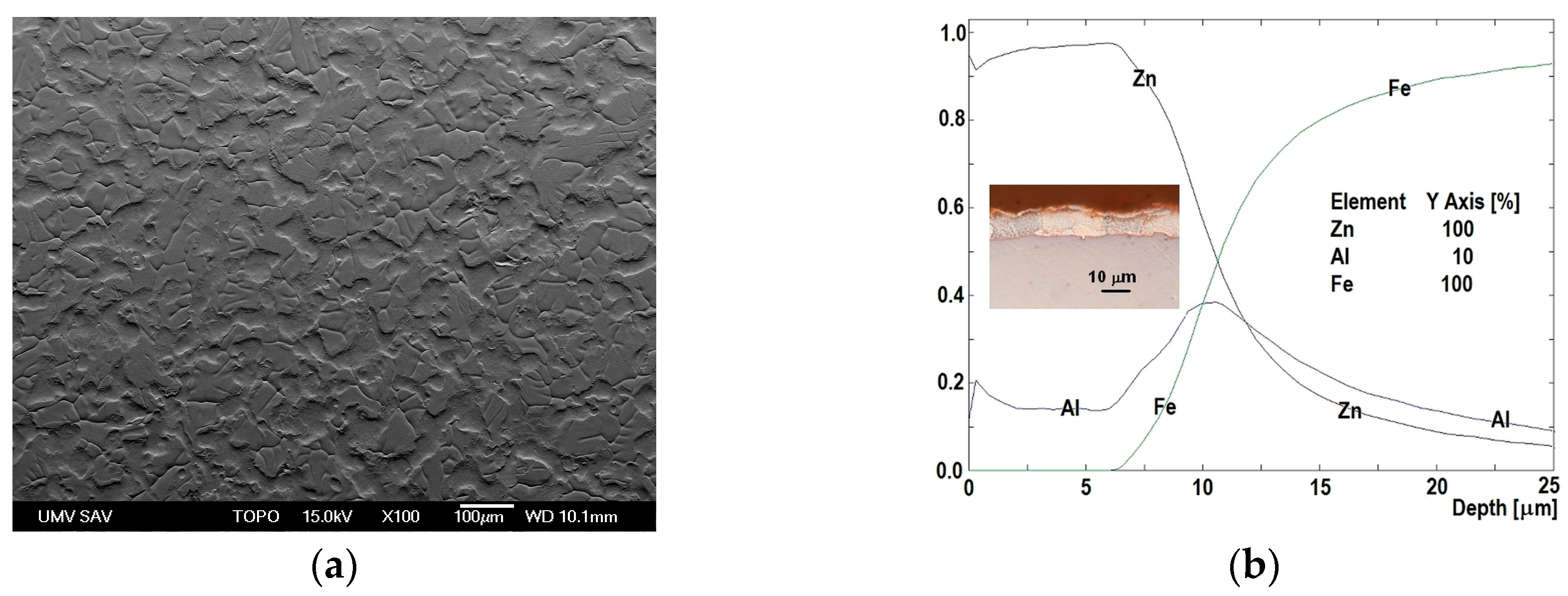
40]. In the process of clinching hot-dip galvanized steel sheets, the surface of the hard PVD coating deposited on the tool (die) comes in contact with a relatively soft zinc layer. There is an interaction between the surface of the hard tool, i.e., the die, and the surface of the zinc layer on the steel sheet [
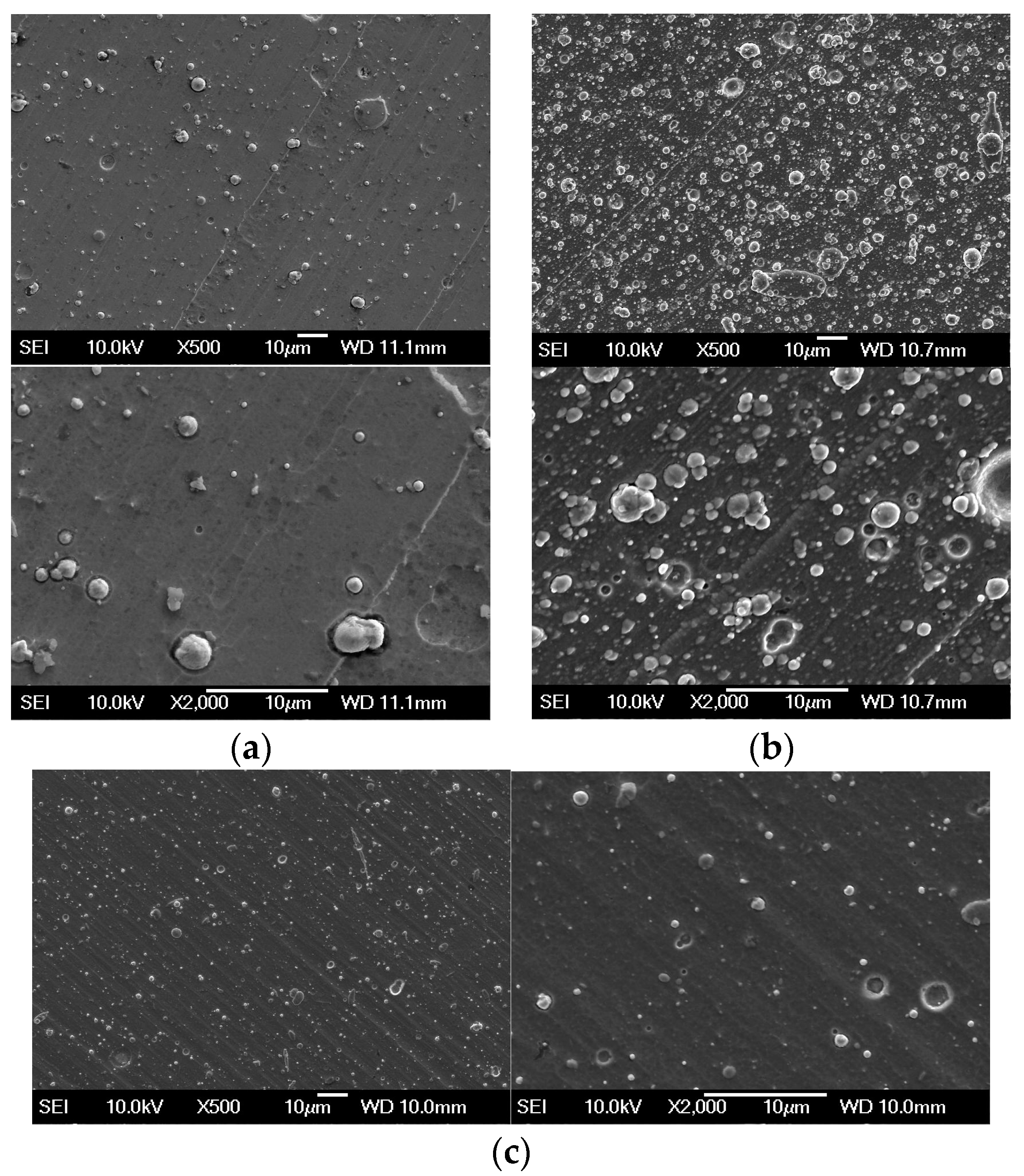
41]. Generally, it is a complex interaction that depends on the manufacturing process conditions and includes the interaction among the material of the sheet, the tool and the lubricant. The initial phase of wear is called galling. It is a form of adhesive wear that causes the transfer of material from the sheet to the forming tool during the forming process [
42,
43]. It results in zinc powdering accompanied with the surface damage or material loss of both bodies of the contact pair [
39,
44]. Experimental research into the phenomenon of galling focused on the influence of the surface topography of the processed sheets [
45], type of PVD coating and roughness of coating deposited on the tool [
46], the microstructure of tool material in relation to galling [
47]. Attempts to develop prediction models for friction and galling were based on the simple contact between the surfaces; nevertheless, the sheet metal forming process is considerably more complicated [
48,
49]. The friction mechanisms depend on various factors, such as physical, chemical and material properties [
39].
Adhesion, hardness, thickness and roughness are the properties of PVD coatings that notably affect the failure mechanism of these coatings [
50,
51,
52,
53,
54]. Adhesion between the coating and the substrate, which is defined as the work necessary to separate the two [
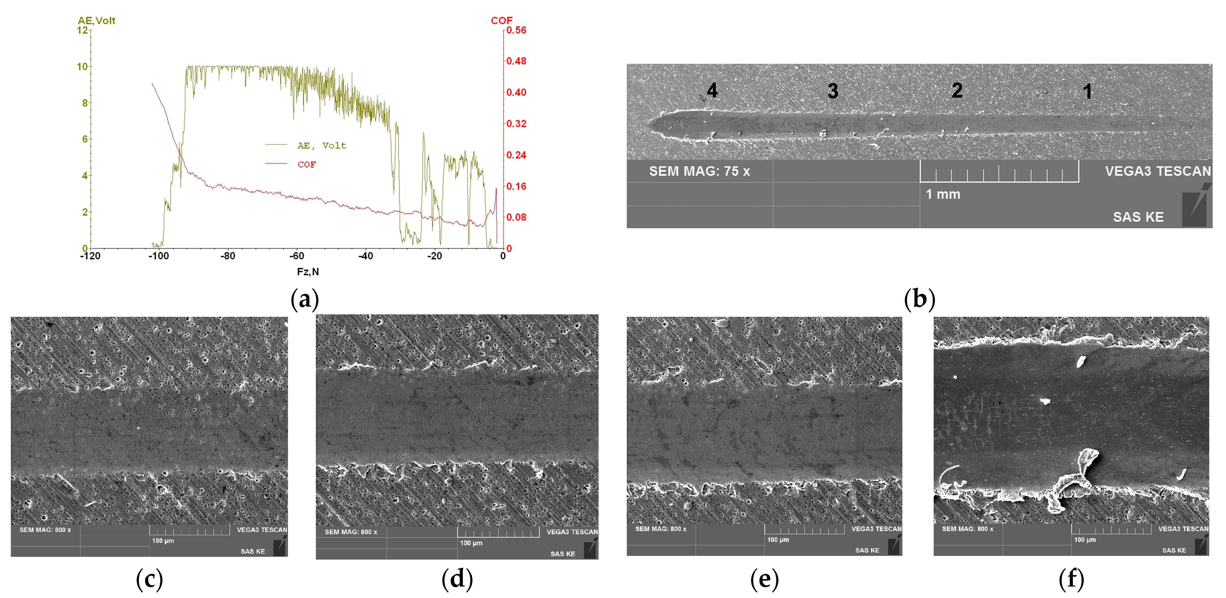
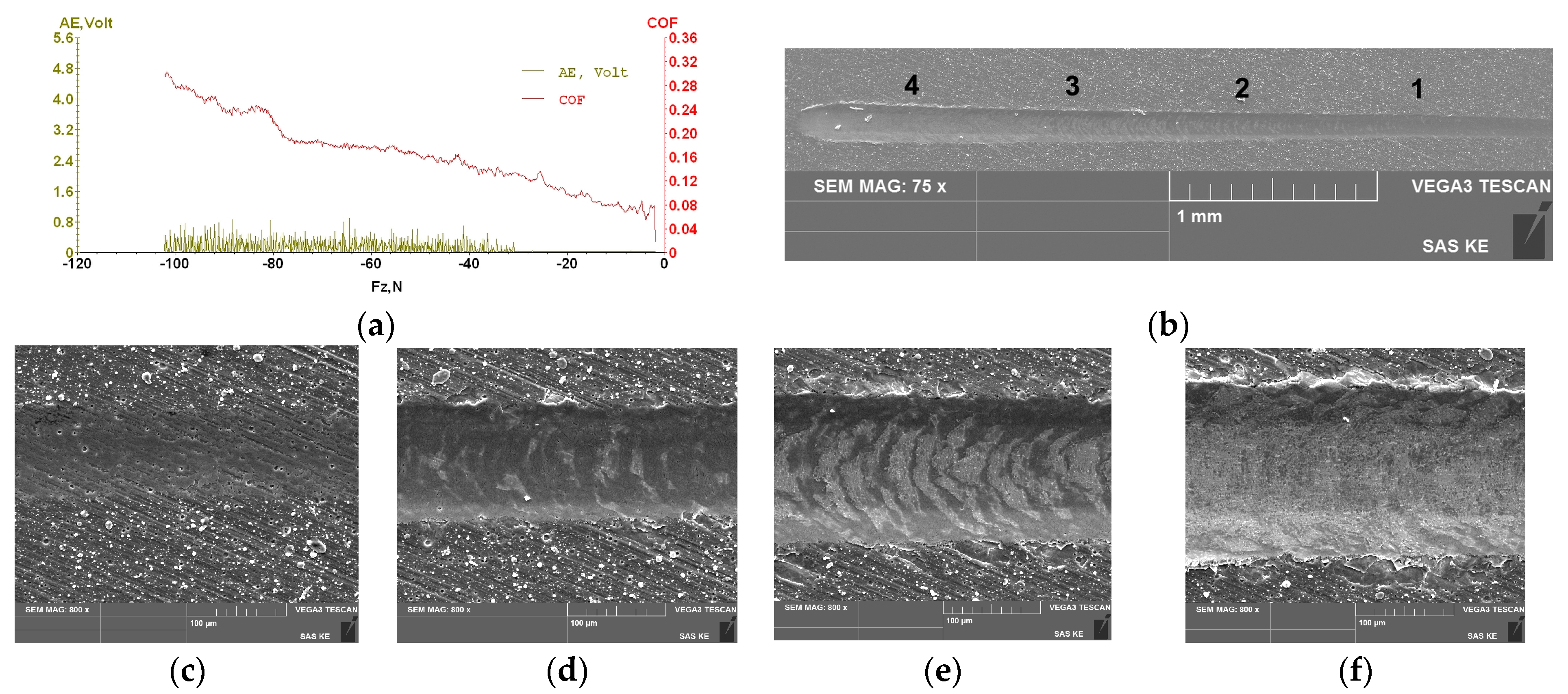
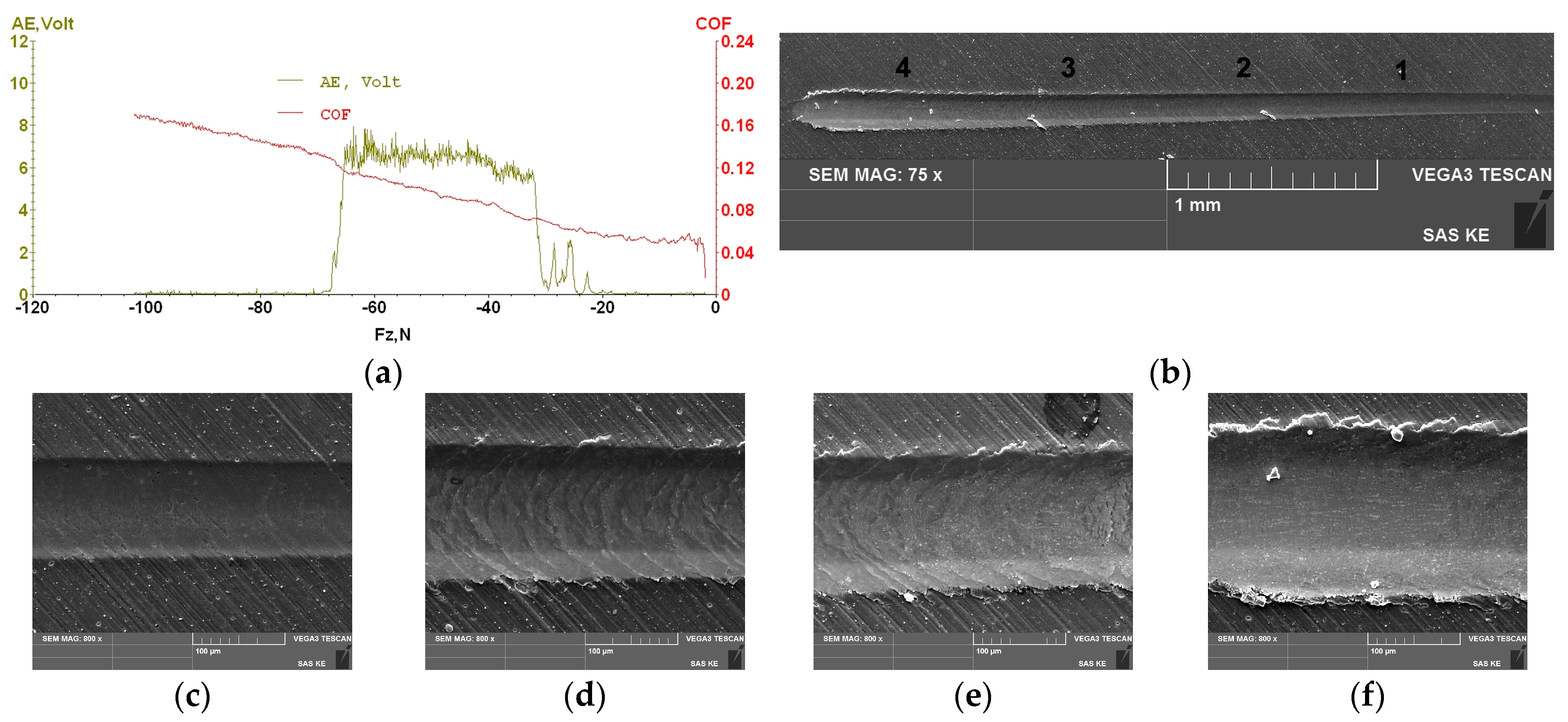
50], is among the basic criteria when evaluating the suitability of the system for a particular use. The most commonly used method for measuring the adhesion, i.e., the bonding strength between the coating and the substrate is the scratch test. After the scratch test, the adhesive properties of PVD coatings are evaluated by examining the morphology of coating failure, using the record of acoustic emission signal, friction coefficient μ and the critical force under which PVD coating is perforated until the substrate appears [
55]. The scratch test and X-ray diffraction proved that the level of residual stress in the coating increases with increased roughness of the material surface on which the PVD coating was deposited [
56]. The aim of the experiments was to identify the die wear mechanisms when clinching thin hot-dip galvanized steel sheets. The punch wear during the clinching process has already been investigated in [
57,
58], which is a mating component to the die in a complex tool for joining by clinching.
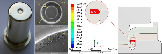
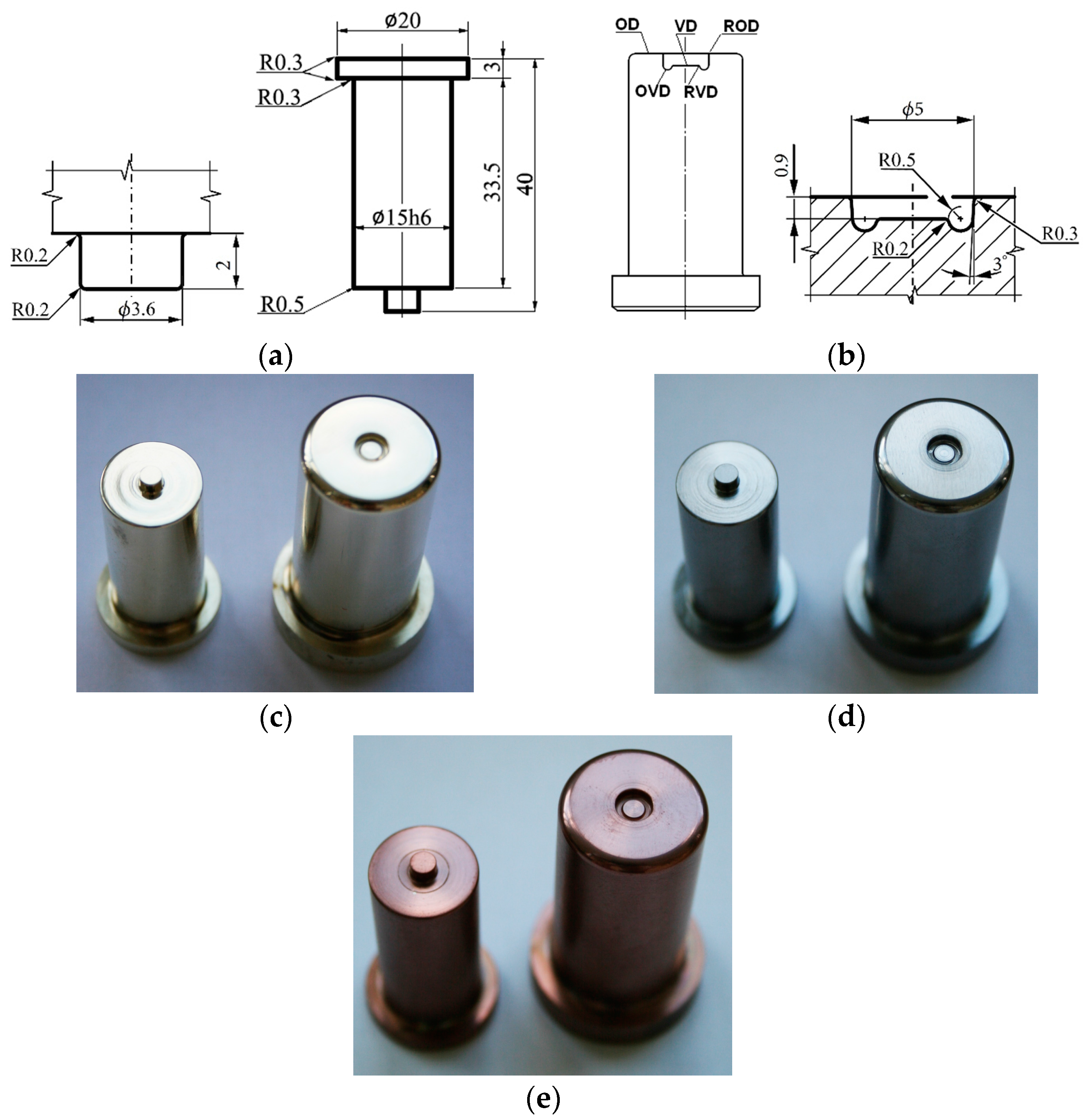
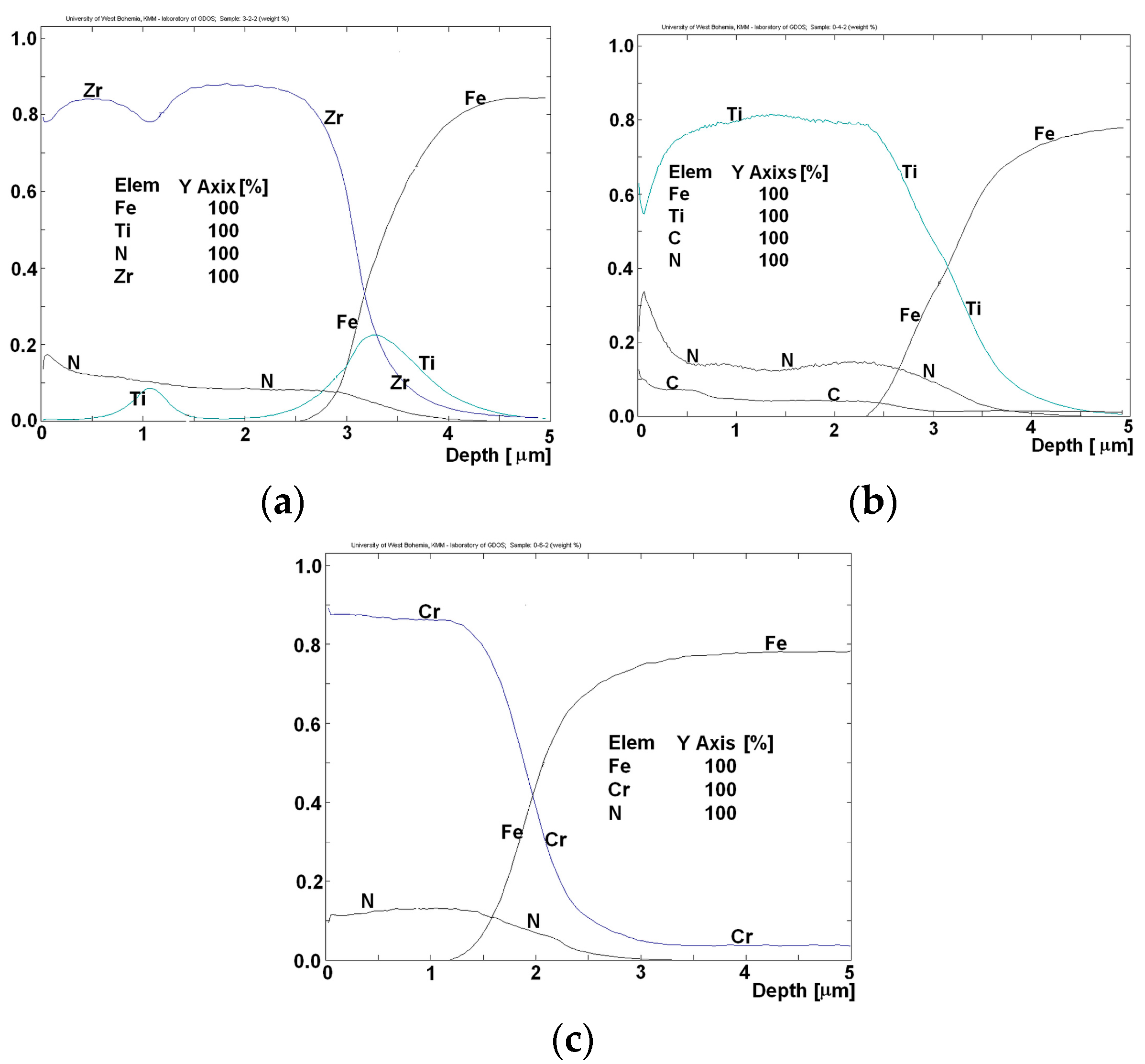
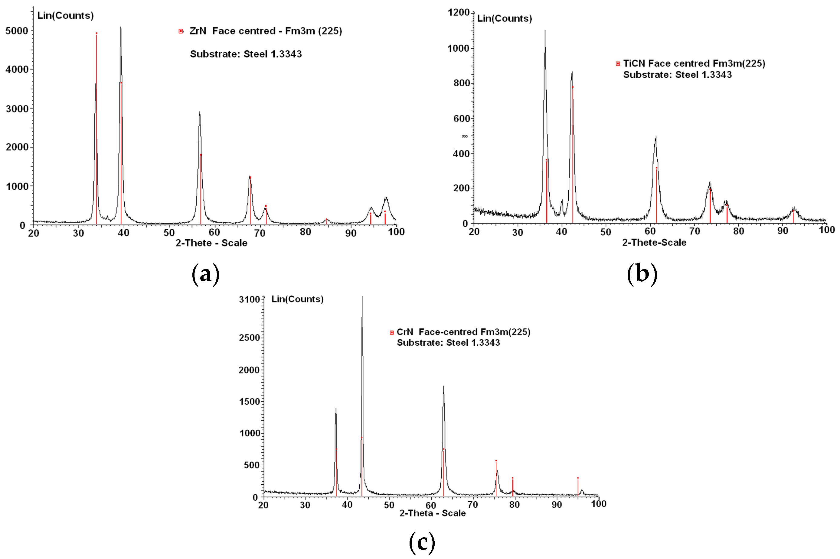
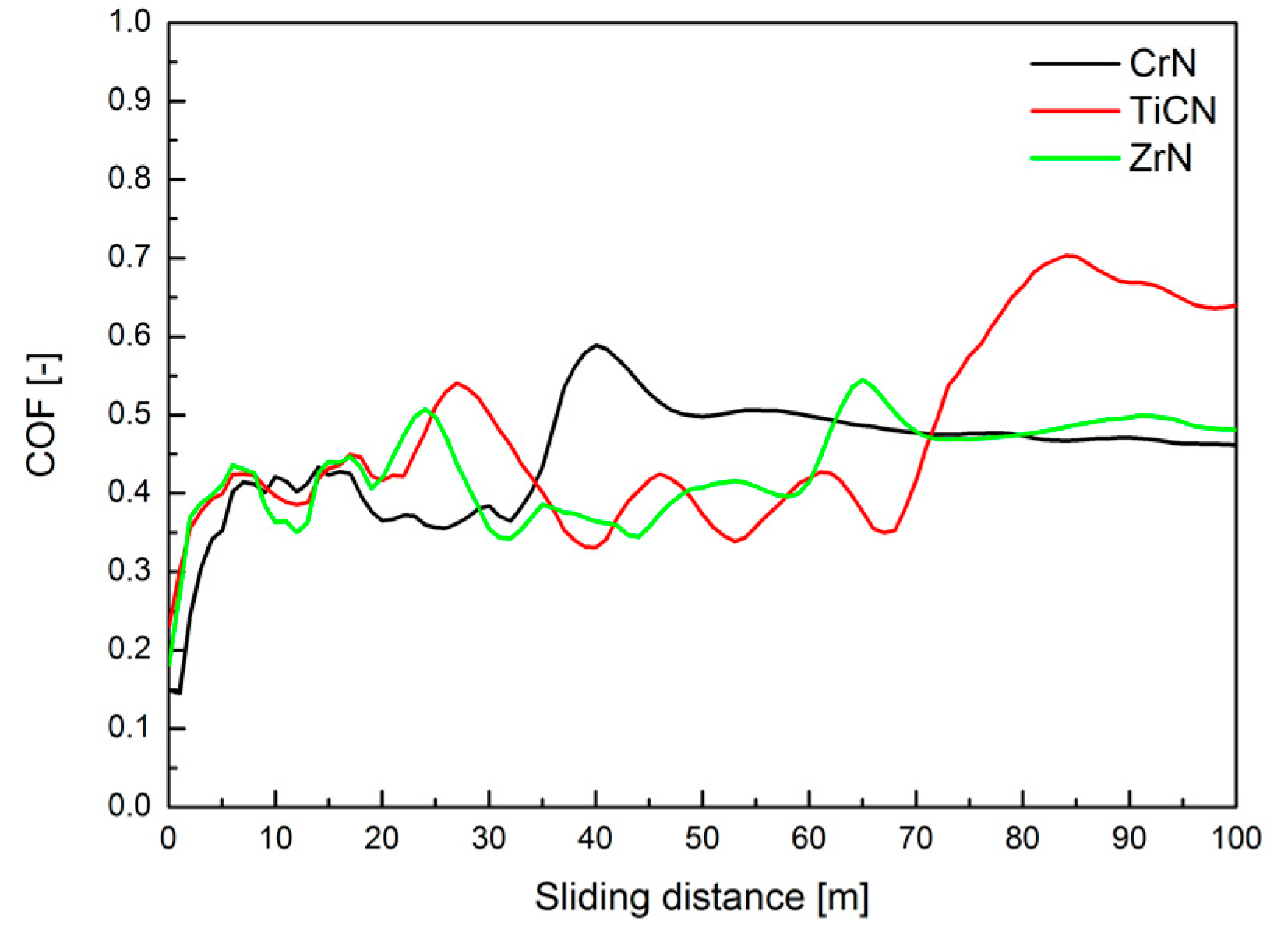
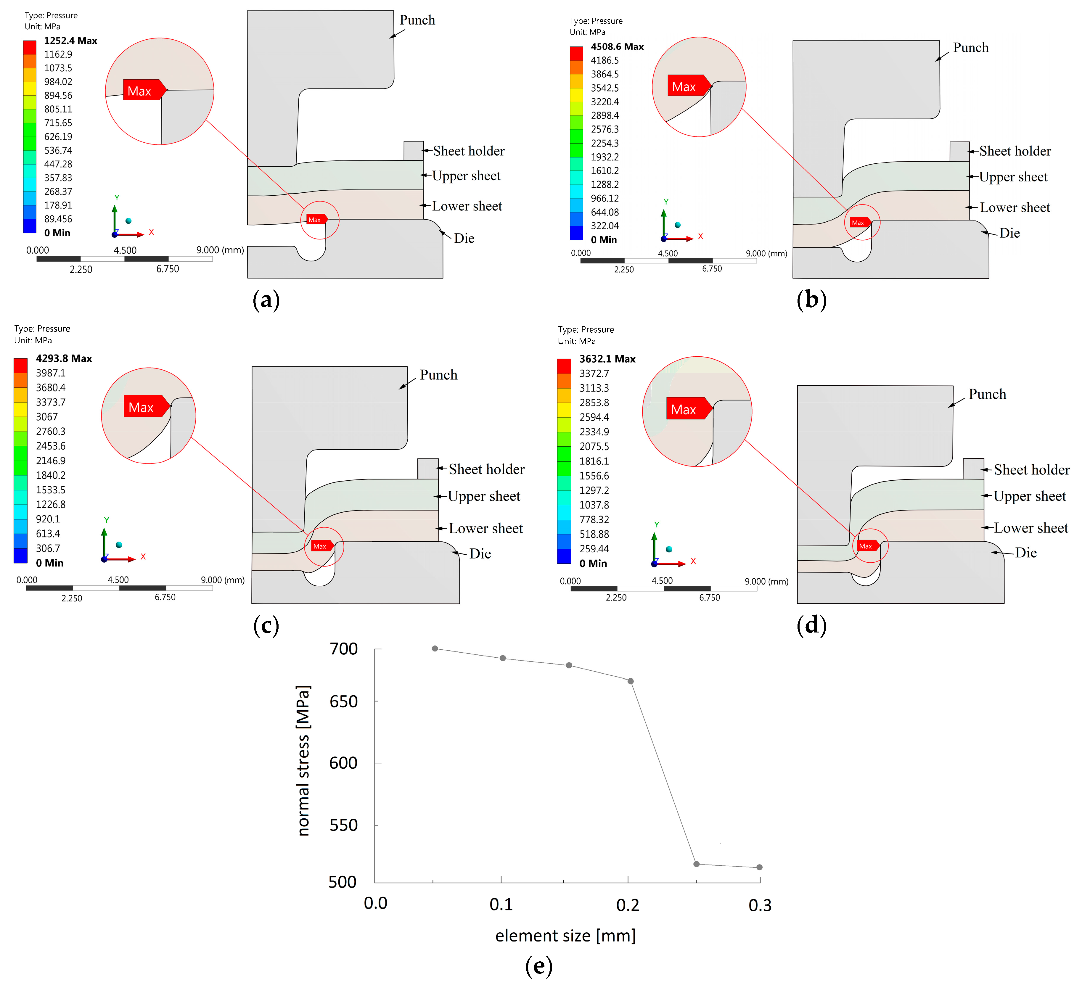
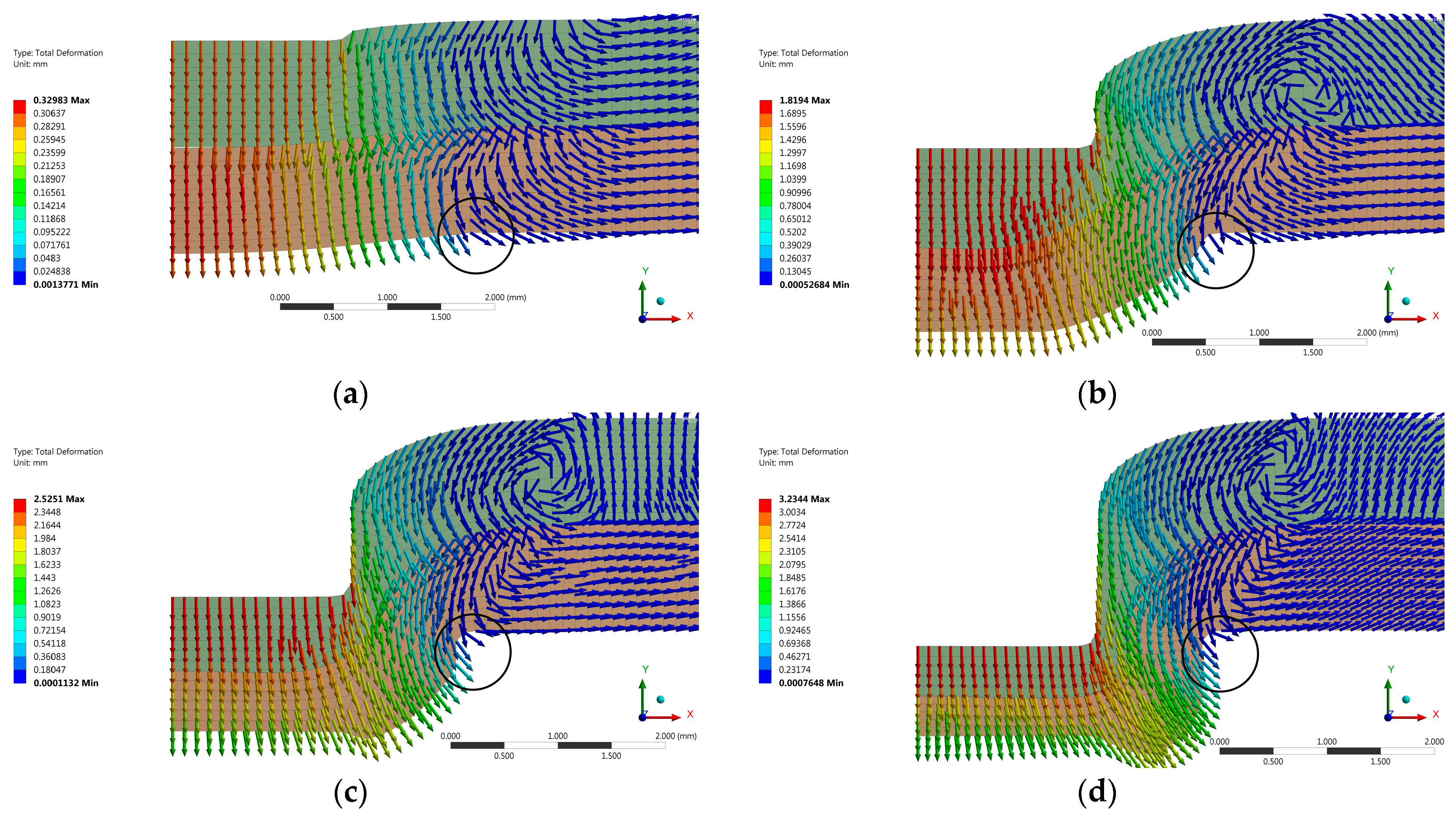
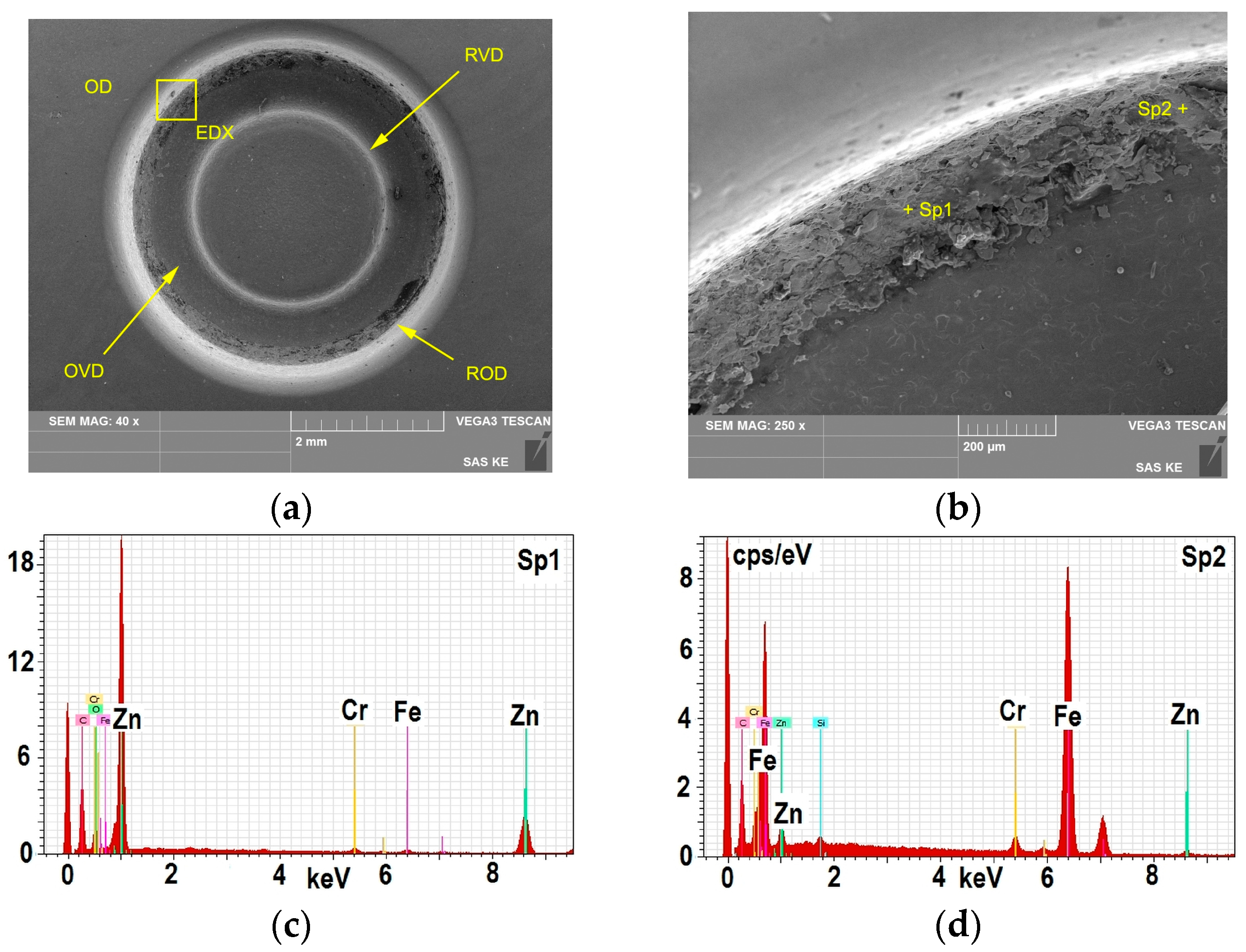
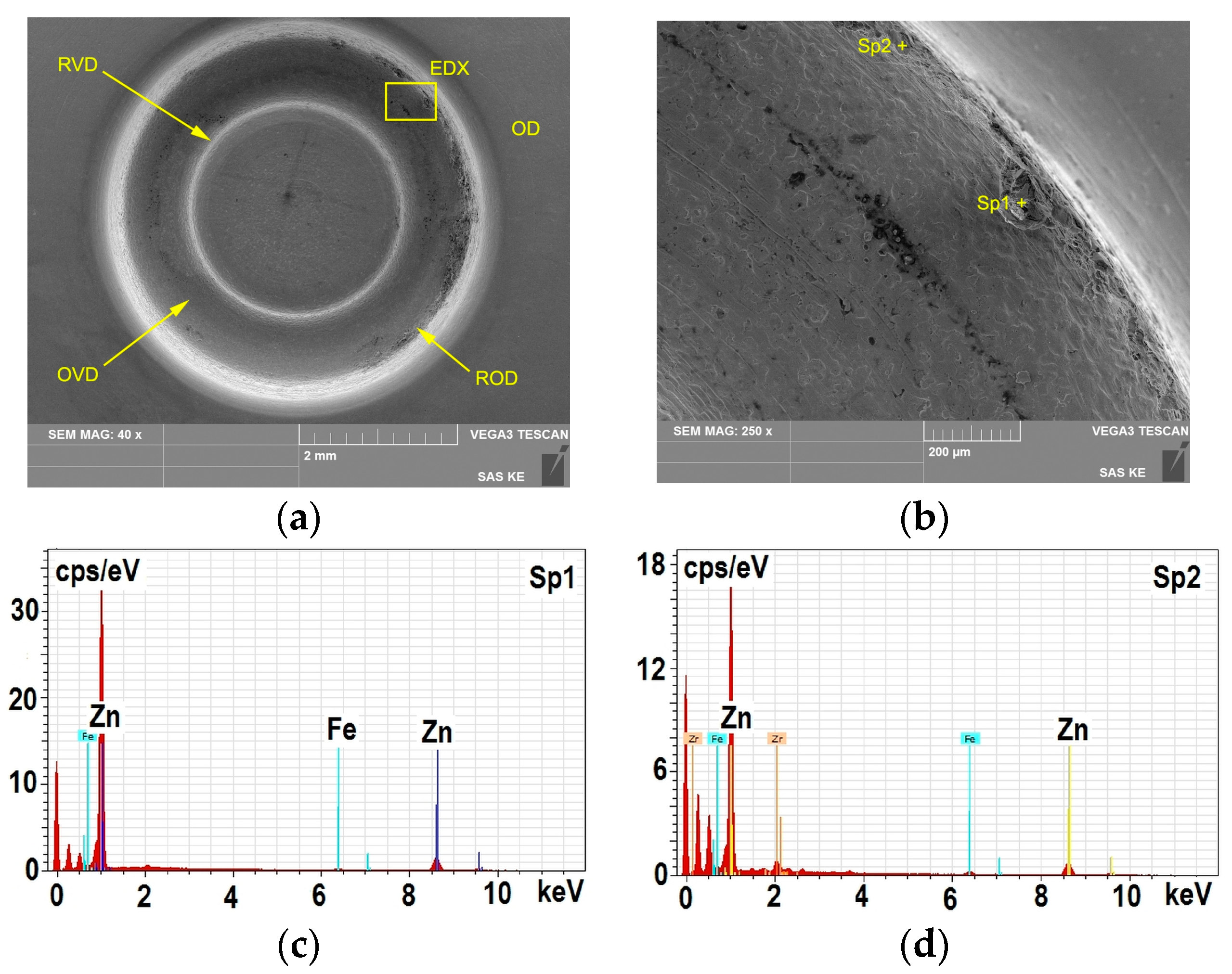
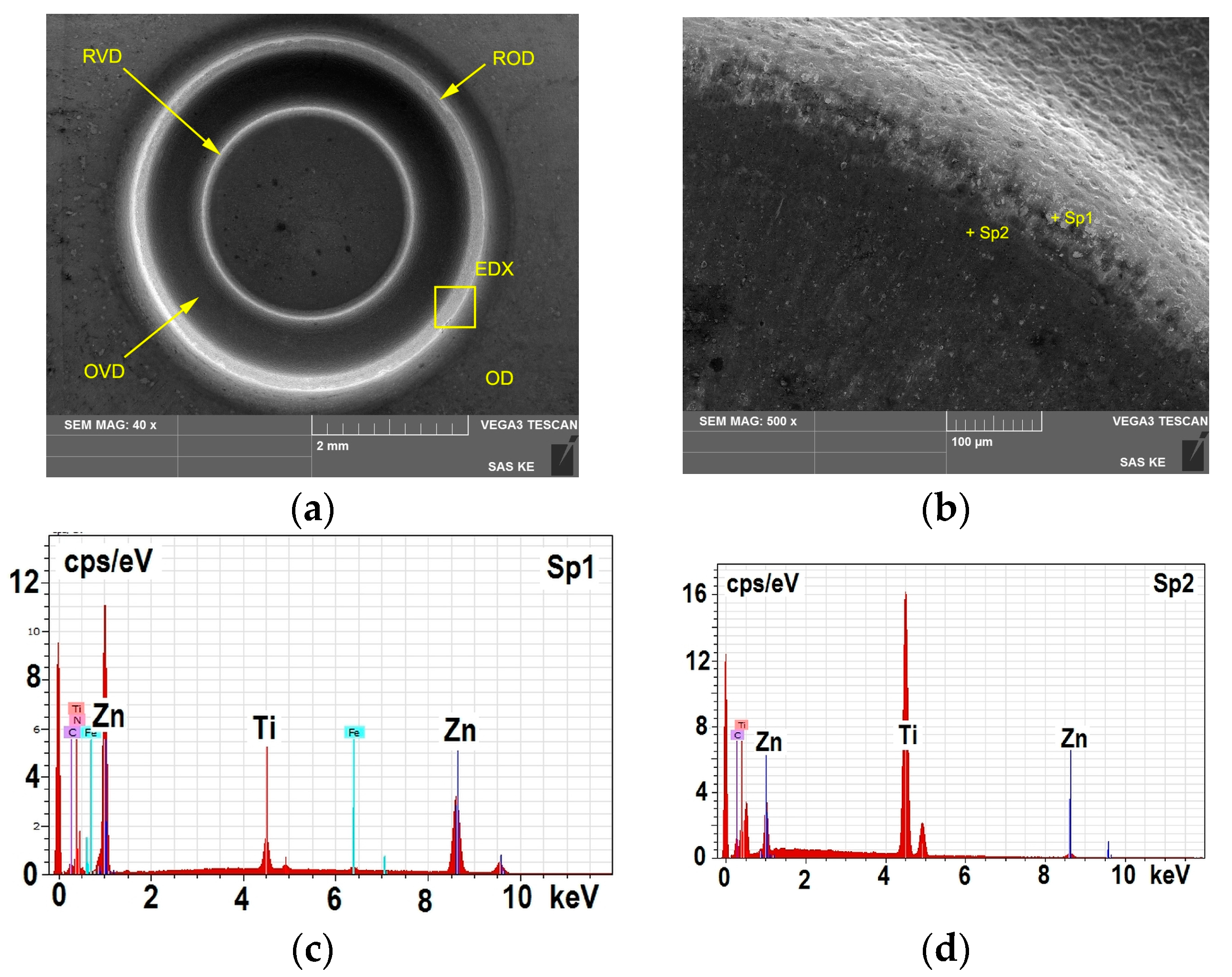
In the research a FEM was used to simulate the clinching process to predict the critical areas, in which the occurrence of wear can be expected. The FEM analysis is based on the ideal state of homogeneous isotropic continuum. The purpose of FEM analysis was to locate the areas that are critical in terms of coating failure. The actual experiment uses a system approach to the identification of the main parameters in the joining process of hot-dip galvanized sheets, which affect the degradation of the tool surface The FEM analysis of stresses in the die during the clinching process provides information about the surface of the shaped area that has the potential to wear as the first. An experimental verification of the prediction of the start of the wear cycle was performed by clinching of hot-dip galvanized steel sheets. Laboratory testing techniques for PVD coatings give only partial information about the wear of the die surface during the clinching process. Friction mechanisms depend on various factors, such as physical, chemical and material properties. A tool made of 1.3343 steel tempered to 55 HRc with PVD coatings of CrN, ZrN and TiCN MP (MP-Multi-Purpose multilayer) was tested at clinching of hot-dip galvanized thin steel sheets H220PD.
A qualitative concept of the stress distribution on the surface and just beneath the surface of the die during the clinching process of hot-galvanized steel sheets could be obtained by Finite Element Analysis (FEA) of stresses. This is a qualitative computation. In actual clinching, the system of the coating on the steel tool substrate interacts with the system of galvanized zinc coating on the steel sheet. The stress-strain interaction of these two systems is a function of physical and geometric parameters that characterize both systems. These parameters affect each other and can vary in intensity during the clinching process.


