
Photogrammetry-Based 3D Textured Point Cloud Models Building and Rock Structure Estimation


Abstract
:1. Introduction
2. The Point Cloud Model Generating for the Study Site
3. Coordinate Transformation
4. The Accuracy Verification of the 3D Point Cloud Model
- (1)
- Identify the specific model and brand of the total station to be tested and make sure that it is properly calibrated and in good working condition.
- (2)
- Choose a suitable outdoor site for the experiment, taking into account factors such as the terrain, weather conditions, and availability of reference points.
- (3)
- Set up the total station at a fixed position and level it carefully. Use a tripod and make sure that the instrument is stable and properly oriented.
- (4)
- Place the measuring pad at a known distance from the total station and mark it clearly with a reflective target or prism.
- (5)
- Take multiple measurements of the measuring pad using the total station, varying the horizontal and vertical angles and the distance. Record the measurements carefully and accurately, taking into account any sources of error or uncertainty.
- (6)
- Repeat the measurements at different times of day or under different weather conditions to assess the effect of environmental factors on the accuracy of the total station.
- (7)
- Compare the measured distances and angles with the actual values of the measuring pad obtained from a reference source with a vernier caliper.
- (8)
- Calculate the errors and uncertainties in the measurements and analyze the results to determine the actual measurement accuracy of the total station under the given conditions.
5. The Rock Structure Analysis for the Rock Slope
6. Summary and Conclusions
- (1)
- The accuracy of the total station is enough as a reference for verifying the accuracy of the 3D point cloud model. The accuracy of the point coordinates of the 3D point cloud model could achieve 3.96 mm. The accuracy of the dip, dip direction, and length are 0.315 degrees, 0.69 degrees, and 0.51 mm, respectively, at a distance of 10 m.
- (2)
- The accuracy of the 3D point cloud model is high enough for engineering applications, taking the coordinates obtained by the total station as a reference. The accuracies of the length, dip, and dip direction are 1.57 mm, 0.38 degrees, and 0.42 degrees, respectively.
- (3)
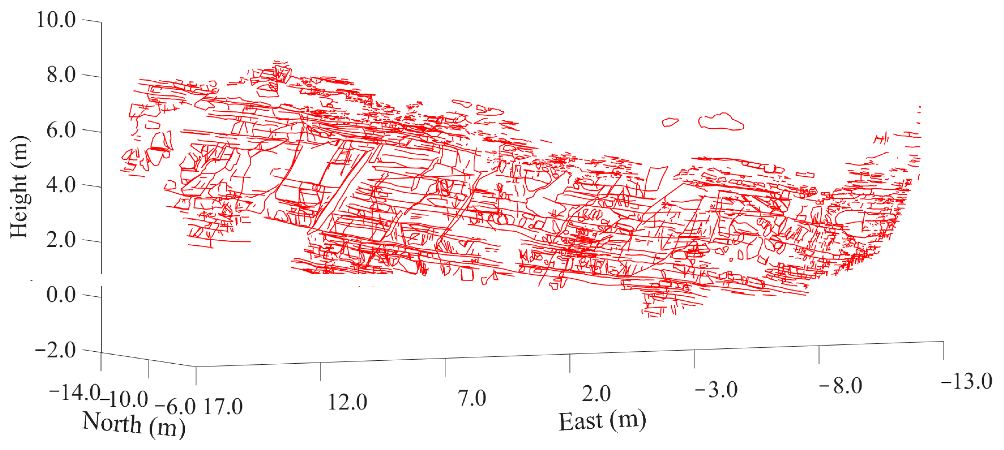
- The method of building a photogrammetry-based 3D point cloud model is applicable. A total of 2993 joint traces of the rock slope were successfully extracted, and the rock structure was estimated with a joint disk model built according to the traces.
- (4)
- The rock structure of the slope is good, according to the value of the rock quality designation. The joints of the slope can be grouped into three sets. The joints in set 1 are generally subhorizontal, with a mean dip value of 14.7°, while the joints in sets 2 and 3 are nearly vertical, with mean dip values of 76.6° and 81.5°, respectively.
Author Contributions
Funding
Institutional Review Board Statement
Informed Consent Statement
Data Availability Statement
Acknowledgments
Conflicts of Interest
Appendix A
| function [Tranformation_matrix ] = Transformation_Matrix(C_From, C_To) % C_From is a 4-by-3 row vector. Coordinates of reference points in Meshroom. % C_To is a 4-by-3 row vector. Coordinates of reference points measured by a total station. % Tranformation_matrix is a 4*4 matrix. It is used for transforming % coordinates from Meshroom to Meshlab. A_From = mean(C_From); A_To = mean(C_To); C_From_MN = C_From-A_From; C_To_MN = C_To-A_To; sFrom = sqrt(sum(C_From_MN(:).^2)/4); sTo = sqrt(sum(C_To_MN(:).^2)/4); s = sTo/sFrom; % Scale factor C_From_MN = C_From_MN/sFrom; C_To_MN = C_To_MN/sTo; H = C_From_MN’*C_To_MN; R = (H’*H)^0.5*inv(H); A = s*R; theory_To = (A*C_From’)’; T = mean(C_To - theory_To); Tranformation_matrix(4, 4) = 1; for i = 1:3 for j = 1:3 Tranformation_matrix(i, j) = A(i, j); end end Tranformation_matrix(1:3, 4) = T’; Tranformation_matrix(4, 1:3) = [0, 0, 0]; End |
References
- Wu, X.; Jiang, Y.; Gong, B.; Guan, Z.; Deng, T. Shear performance of rock joint reinforced by fully encapsulated rock bolt under cyclic loading condition. Rock Mech. Rock Eng. 2019, 52, 2681–2690. [Google Scholar] [CrossRef]
- Tzamos, S.; Sofianos, A. A correlation of four rock mass classification systems through their fabric indices. Int. J. Rock Mech. Min. Sci. 2007, 44, 477–495. [Google Scholar] [CrossRef]
- Bahaaddini, M.; Sharrock, G.; Hebblewhite, B.K. Numerical investigation of the effect of joint geometrical parameters on the mechanical properties of a nonpersistent jointed rock mass under uniaxial compression. Comput. Geotech. 2013, 49, 206–225. [Google Scholar] [CrossRef]
- Ban, L.; Zhu, C.; Qi, C.; Tao, Z. New roughness parameters for 3D roughness of rock joints. Bull. Eng. Geol. Environ. 2019, 78, 4505–4517. [Google Scholar] [CrossRef]
- Liu, T.; Deng, J.; Zheng, J.; Zheng, L.; Zhang, Z.; Zheng, H. A new semi-deterministic block theory method with digital photogrammetry for stability analysis of a high rock slope in China. Eng. Geol. 2017, 216, 76–89. [Google Scholar] [CrossRef]
- Chen, J.Y.; Huang, H.W.; Zhou, M.L.; Chaiyasarn, K. Towards semi-automatic discontinuity characterization in rock tunnel faces using 3D point clouds. Eng. Geol. 2021, 291, 106232. [Google Scholar] [CrossRef]
- Deb, D.; Hariharan, S.; Rao, U.M.; Ryu, C.-H. Automatic detection and analysis of discontinuity geometry of rock mass from digital images. Comput. Geosci. 2008, 34, 115–126. [Google Scholar] [CrossRef]
- Fujii, Y.; Fodde, E.; Watanabe, K.; Murakami, K. Digital photogrammetry for the documentation of structural damage in earthen archaeological sites: The case of Ajina Tepa, Tajikistan. Eng. Geol. 2009, 105, 124–133. [Google Scholar] [CrossRef] [Green Version]
- Fujii, Y.; Shogaki, T.; Miyakawa, M. Photogrammetric documentation and non-invasive investigation of a stone dry dock, the Yokosuka arsenal dry dock no. 1, Japan. Eng. Geol. 2018, 234, 122–131. [Google Scholar] [CrossRef]
- Guo, J.; Liu, S.; Zhang, P.; Wu, L.; Zhou, W.; Yu, Y. Towards semi-automatic rock mass discontinuity orientation and set analysis from 3D point clouds. Comput. Geosci. 2017, 103, 164–172. [Google Scholar] [CrossRef]
- Sturzenegger, M.; Stead, D. Close-range terrestrial digital photogrammetry and terrestrial laser scanning for discontinuity characterization on rock cuts. Eng. Geol. 2009, 106, 163–182. [Google Scholar] [CrossRef]
- Kaminski, M.; Zientara, P.; Krawczyk, M. Electrical resistivity tomography and digital aerial photogrammetry in the research of the “Bachledzki Hill” active landslide–in Podhale (Poland). Eng. Geol. 2021, 285, 106004. [Google Scholar] [CrossRef]
- Cheng, Z.; Gong, W.P.; Tang, H.M.; Juang, C.H.; Deng, Q.; Chen, J.; Ye, X. UAV photogrammetry-based remote sensing and preliminary assessment of the behavior of a landslide in Guizhou, China. Eng. Geol. 2021, 289, 106172. [Google Scholar] [CrossRef]
- Nappo, N.; Mavrouli, O.; Nex, F.; Van, C.; Gambillara, R.; Michetti, A.M. Use of UAV-based photogrammetry products for semi-automatic detection and classification of asphalt road damage in landslide-affected areas. Eng. Geol. 2021, 294, 106363. [Google Scholar] [CrossRef]
- Buyer, A.; Aichinger, S.; Schubert, W. Applying photogrammetry and semiautomated joint mapping for rock mass characterization. Eng. Geol. 2020, 264, 105332. [Google Scholar] [CrossRef]
- Menegoni, N.; Giordan, D.; Perotti, C.; Tannant, D. Detection and geometric characterization of rock mass discontinuities using a 3D high-resolution digital outcrop model generated from RPAS imagery-Ormea rock slope, Italy. Eng. Geol. 2019, 252, 145–163. [Google Scholar] [CrossRef]
- Lato, M.; Kemeny, J.; Harrap, R.M.; Bevan, G. Rock bench: Establishing a common repository and standards for assessing rockmass characteristics using LiDAR and photogrammetry. Comp. Geosci. 2013, 50, 106–114. [Google Scholar] [CrossRef]
- Sturzenegger, M.; Stead, D.; Elmo, D. Terrestrial remote sensing-based estimation of mean trace length, trace intensity and block size/shape. Eng. Geol. 2011, 119, 96–111. [Google Scholar] [CrossRef]
- Laribi, A.; Walstra, J.; Ougrine, M.; Seridi, A.; Dechemi, N. Use of digital photogrammetry for the study of unstable slopes in urban areas: Case study of the El Biar landslide, Algiers. Eng. Geol. 2015, 187, 73–83. [Google Scholar] [CrossRef]
- Mora, P.; Baldi, P.; Casula, G.; Fabris, M.; Ghirotii, M.; Mazzioni, E.; Pesci, A. Global positioning systems and digital photogrammetry for monitoring of mass movements: Application to the Ca’ di Malta landslide (northern Apennines, Italy). Eng. Geol. 2003, 68, 103–121. [Google Scholar] [CrossRef]
- Kabsch, W. A Solution for the Best Rotation to Relate Two Sets of Vectors. Acta. Cryst. A 1976, 32, 922–923. [Google Scholar] [CrossRef]
- Robertson, A. The interpretation of geological factors for use in slope theory. In Planning Open Pit Mines: Proceedings of the Symposium on the Theoretical; SAIMM: Johannesburg, South Africa, 1970; pp. 55–71. [Google Scholar]
- Baecher, G.B.; Lanney, N.S.; Einstein, H.H. Statistical descriptions of rock properties and sampling. In Proceedings of the 18th US Symposium on Rock Mechanics (USRMS), Golden, CO, USA, 22–24 June 1977; OnePetro: Richardson, TX, USA, 1977. [Google Scholar]
- Lei, Q.; Latham, J.P.; Tsang, C.F. The use of discrete fracture networks for modelling coupled geomechanical and hydrological behaviour of fractured rocks. Comput. Geotech. 2017, 85, 151–176. [Google Scholar] [CrossRef]
- Liu, T.; Zheng, J.; Deng, J. A new iteration clustering method for rock discontinuity sets considering discontinuity trace lengths and orientations. Bull. Eng. Geol. Environ. 2021, 80, 413–428. [Google Scholar] [CrossRef]
- Liu, T.; Jiang, A.; Deng, J.; Zheng, J.; Zhang, Z. A new multiple-factor clustering method considering both box fractal dimension and orientation of joints. J. Rock Mech. Geotech. Eng. 2021, 14, 366–376. [Google Scholar] [CrossRef]
- Zhang, W.; Lan, Z.; Ma, Z.; Tan, C.; Que, J.; Wang, F. Determination of statistical discontinuity persistence for a rock mass characterized by non-persistent fractures. Int. J. Rock Mech. Min. Sci. 2020, 126, 104177. [Google Scholar] [CrossRef]
- Hammah, R.E.; Curran, J.H. Fuzzy cluster algorithm for the automatic identification of joint sets. Int. J. Rock Mech. Min. Sci. 1998, 35, 889–905. [Google Scholar] [CrossRef]
- Ma, G.; Xu, Z.; Zhang, W.; Li, S. An enriched K-means clustering method for grouping joints with meliorated initial centers. Arab. J. Geosci. 2015, 8, 1881–1893. [Google Scholar] [CrossRef]
- Mauldon, M.; Dunne, W.M.; Rohrbaugh, M.B. Circular scanlines and circular windows: New tools for characterizing the geometry of fracture traces. J. Struct. Geol. 2001, 23, 247–258. [Google Scholar] [CrossRef]
- Nie, Z.; Chen, J.; Zhang, W.; Chun, T. A new method for three-dimensional fracture network modelling for trace data collected in a large sampling window. Rock Mech. Rock Eng. 2019, 53, 1145–1161. [Google Scholar] [CrossRef]
- Warburton, P.M. A stereological interpretation of joint trace data. Int. J. Rock Mech. Min. Sci. Geomech. Abstr. 1980, 17, 181–190. [Google Scholar] [CrossRef]


| No. | 1 | 2 | 3 | 4 | 5 | 6 | 7 | |
|---|---|---|---|---|---|---|---|---|
| Distance between the total station and the measuring pod (m) | 10 | 10 | 10 | 10 | 30 | 50 | 100 | |
| Orientation obtained by compass (°) | Dip direction | 277 | 9 | 93 | 192 | 285 | 274 | 313 |
| Dip | 53 | 53 | 54 | 51 | 50 | 50 | 54 | |
| Orientation calculated from coordinates (°) | Dip direction | 277.20 | 10.19 | 93.78 | 192.59 | 286.09 | 275.90 | 314.88 |
| Dip | 52.63 | 53.67 | 54.14 | 51.08 | 50.83 | 50.55 | 55.25 | |
| Distances obtained by vernier caliper (mm) | AB | 174.62 | ||||||
| BC | 178.54 | |||||||
| CD | 246.22 | |||||||
| DE | 175.02 | |||||||
| EF | 173.64 | |||||||
| FA | 240.10 | |||||||
| AG | 211.66 | |||||||
| GD | 217.22 | |||||||
| CG | 215.44 | |||||||
| GF | 209.22 | |||||||
| Distances calculated from coordinates (mm) | AB | 174.39 | 174.58 | 174.03 | 174.59 | 173.92 | 174.11 | 172.47 |
| BC | 178.32 | 177.82 | 179.29 | 178.43 | 178.30 | 178.02 | 176.86 | |
| CD | 245.71 | 246.10 | 245.32 | 246.45 | 246.28 | 244.90 | 249.10 | |
| DE | 175.01 | 174.88 | 174.83 | 174.90 | 174.89 | 175.24 | 175.44 | |
| EF | 173.23 | 173.27 | 173.63 | 173.19 | 173.08 | 172.57 | 173.98 | |
| FA | 239.96 | 240.31 | 239.07 | 241.05 | 239.90 | 240.12 | 239.61 | |
| AG | 212.09 | 212.62 | 210.08 | 212.70 | 211.36 | 211.44 | 213.91 | |
| GD | 217.07 | 217.09 | 217.77 | 217.10 | 217.42 | 216.48 | 216.26 | |
| CG | 214.79 | 213.35 | 216.82 | 215.17 | 215.27 | 214.66 | 215.01 | |
| GF | 208.78 | 209.78 | 208.04 | 208.93 | 208.40 | 209.00 | 207.49 | |
| Absolute values of orientation differences (°) | Dip direction | 0.20 | 1.19 | 0.78 | 0.59 | 1.09 | 1.90 | 1.88 |
| Dip | 0.37 | 0.67 | 0.14 | 0.08 | 0.83 | 0.55 | 1.25 | |
| Absolute values of distance differences (mm) | AB | 0.23 | 0.04 | 0.59 | 0.03 | 0.70 | 0.51 | 2.15 |
| BC | 0.22 | 0.72 | 0.75 | 0.11 | 0.24 | 0.52 | 1.68 | |
| CD | 0.51 | 0.12 | 0.90 | 0.23 | 0.06 | 1.32 | 2.88 | |
| DE | 0.01 | 0.14 | 0.19 | 0.12 | 0.13 | 0.22 | 0.42 | |
| EF | 0.41 | 0.37 | 0.01 | 0.45 | 0.56 | 1.07 | 0.34 | |
| FA | 0.14 | 0.21 | 1.03 | 0.95 | 0.20 | 0.02 | 0.49 | |
| AG | 0.43 | 0.96 | 1.58 | 1.04 | 0.30 | 0.22 | 2.25 | |
| GD | 0.15 | 0.13 | 0.55 | 0.12 | 0.20 | 0.74 | 0.96 | |
| CG | 0.65 | 2.09 | 1.38 | 0.27 | 0.17 | 0.78 | 0.43 | |
| GF | 0.44 | 0.56 | 1.18 | 0.29 | 0.82 | 0.22 | 1.73 | |
| Mean value (mm) | 0.32 | 0.53 | 0.82 | 0.36 | 0.34 | 0.56 | 1.33 | |
| No. | Start Point Series Number | Endpoint Series Number | Length Calculated Based on Coordinates Extracted from Meshlab (m) | Length Calculated Based on Coordinates Extracted from Total Station (m) | Absolute Value of Difference of Two Lengths (mm) |
|---|---|---|---|---|---|
| 1 | 5 | 18 | 20.9986 | 21.0002 | 1.6 |
| 2 | 6 | 19 | 20.9473 | 20.9466 | 0.7 |
| 3 | 7 | 20 | 21.0564 | 21.0564 | 0.0 |
| 4 | 8 | 21 | 7.5396 | 7.5405 | 0.9 |
| 5 | 9 | 22 | 6.3363 | 6.3389 | 2.6 |
| 6 | 10 | 23 | 5.5685 | 5.5653 | 3.2 |
| 7 | 11 | 24 | 7.2291 | 7.2286 | 0.5 |
| 8 | 12 | 25 | 7.2948 | 7.2932 | 1.6 |
| 9 | 13 | 26 | 11.5674 | 11.5693 | 1.9 |
| 10 | 14 | 27 | 9.8953 | 9.8936 | 1.7 |
| 11 | 15 | 28 | 6.6601 | 6.6637 | 3.7 |
| 12 | 16 | 29 | 4.3543 | 4.3546 | 0.3 |
| 13 | 17 | 30 | 4.6618 | 4.6601 | 1.7 |
| Mean value | 1.57 |
| No. | Point Series Numbers | Orientation Calculated Based on Coordinates Extracted from Meshlab (°) | Orientation Calculated Based on Coordinates Obtained from Total Station (°) | Absolute Value of Difference of Two Orientations (°) | |||
|---|---|---|---|---|---|---|---|
| Dip | Dip Direction | Dip | Dip Direction | Dip | Dip Direction | ||
| 1 | 5, 6, 7 | 68.2 | 157.2 | 67.7 | 157.5 | 0.5 | 0.3 |
| 2 | 10, 11, 12 | 68.7 | 203.1 | 68.4 | 203.7 | 0.3 | 0.6 |
| 3 | 15, 16, 17 | 86.5 | 157.2 | 86.7 | 157.2 | 0.2 | 0.0 |
| 4 | 18, 19, 20 | 78.9 | 342.3 | 79.6 | 341.8 | 0.7 | 0.5 |
| 5 | 21, 22, 23 | 71.2 | 153.5 | 71.4 | 152.8 | 0.2 | 0.7 |
| Mean value | 0.38 | 0.42 | |||||
| Joint Set Series | Volume Density (m−3) | Orientation (Fisher Distribution) | Diameter (Lognormal Distribution) | |||
|---|---|---|---|---|---|---|
| Dip Direction (°) | Dip (°) | KF | Mean Value (m) | Variance (m2) | ||
| 1 | 3.02 | 335.6 | 14.7 | 12.0 | 0.67 | 1.28 |
| 2 | 7.86 | 179.4 | 76.6 | 7.1 | 0.38 | 0.22 |
| 3 | 3.99 | 90.1 | 81.5 | 8.1 | 0.31 | 0.12 |
Disclaimer/Publisher’s Note: The statements, opinions and data contained in all publications are solely those of the individual author(s) and contributor(s) and not of MDPI and/or the editor(s). MDPI and/or the editor(s) disclaim responsibility for any injury to people or property resulting from any ideas, methods, instructions or products referred to in the content. |
© 2023 by the authors. Licensee MDPI, Basel, Switzerland. This article is an open access article distributed under the terms and conditions of the Creative Commons Attribution (CC BY) license (https://creativecommons.org/licenses/by/4.0/).
Share and Cite
Liu, T.; Deng, J. Photogrammetry-Based 3D Textured Point Cloud Models Building and Rock Structure Estimation. Appl. Sci. 2023, 13, 4977. https://doi.org/10.3390/app13084977
Liu T, Deng J. Photogrammetry-Based 3D Textured Point Cloud Models Building and Rock Structure Estimation. Applied Sciences. 2023; 13(8):4977. https://doi.org/10.3390/app13084977
Chicago/Turabian StyleLiu, Tiexin, and Jianhui Deng. 2023. "Photogrammetry-Based 3D Textured Point Cloud Models Building and Rock Structure Estimation" Applied Sciences 13, no. 8: 4977. https://doi.org/10.3390/app13084977
APA StyleLiu, T., & Deng, J. (2023). Photogrammetry-Based 3D Textured Point Cloud Models Building and Rock Structure Estimation. Applied Sciences, 13(8), 4977. https://doi.org/10.3390/app13084977