Thermal Management Systems for Civil Aircraft Engines: Review, Challenges and Exploring the Future


Abstract
:1. Introduction
- Phase 1: Pioneering work: The first two decades (between 1958 and 1978). The first theoretical studies and embodiments’ presentation were undertaken, resulting in generation of the main ideas for the aerospace TMS: using two heat exchangers for the engine thermal management, using catalyst to increase the fuel heat capacity and oil flowrate tuning through the heat exchangers to control the engine fuel temperature. These ideas helped researchers to build a very strong integration phase in the field.
- Phase 2: Integration: The second two decades (between 1978 and 1998). The idea of having integrated thermal management system for engine and airframe is presented and discussed in several embodiments in this phase. Moreover, the most practical idea for the TMS structure, having two separate cooling loops for the management of engine heat loads, is also proposed and developed.
- Phase 3: Detailed Design: The last two decades (between 1998 and 2018). More comprehensive studies based on detailed testing and real applications were published in this phase. The ideas of new advanced structures for the TMS, fuel temperature control in TMS and using different cooling fluids like water, Therminol, which is a synthetic heat transfer fluid and thermally neutral heat transfer fluid (TNHTF) are presented and discussed as well.
2. Pioneering Work on Thermal Management Systems Design
- (1)
- Using two heat exchangers to manage the excess heat of the engine: FOHE and AOHE
- (2)
- Using a catalyst to increase the fuel heat absorption capacity
- (3)
- Tuning the oil flow rate through the FOHE to control the engine fuel temperature
3. Integration Phase on Thermal Management Systems Design
- (1)
- The main heat sources of the engine like bearings and accessory gearbox will be cooled (and also lubricated) by main oil loop in which the oil will be distributed and collected throughout the main engine structure and then it will be returned to a collection point after absorbing excess heat generated by the engine components.
- (2)
- Another oil loop is designed to lubricate and to dissipate extra heat from accessory drive like constant speed drive for the aircraft service electrical generator.
- (1)
- Integrated cooling system for the engine and airframe
- (2)
- Designing two separate cooling paths for the engine thermal management
- (3)
- Integrating airframe and engine fuel heat sink systems into a composite heat sink and a secondary power source
4. Detailed Design Phase on Thermal Management Systems
- (1)
- The first step in designing an optimized TMS for an aircraft engine is to precisely define the boundary conditions and to recognize the requirements and constraints of the specific system.
- (2)
- Different approaches should be taken for different applications and aircraft platform in order to optimize the power and TMS.
- (3)
- Different levels of heat flux should be discussed in detail and suitable approaches for each level should be proposed.
- (4)
- Since all power system components such as batteries, capacitors, power semiconductors, generators, pulsed power sources and beam conditioners have thermal design issues, partial solutions have been sought by way of increased heat transfer through the use of spray cooling, micro channels and subcooled boiling, loop heat pipes, capillary pumped loops, energy storage and spray cooling arrays.
- (1)
- The first system includes an air/oil heat exchanger and an oil/fuel heat exchanger as shown in Figure 4. A small percentage of the fan bypass duct air flow passes through the Air-to-Oil heat exchanger (AOH). This embodiment not only adds weight to the aircraft but also creates a pressure loss in the fan bypass duct airflow (BPA), resulting in a reduction in propulsive thrust.
- (2)
- The second idea is shown in Figure 5 includes an oil/fuel heat exchanger (OFH) that transfers heat from the hot engine oil. However, the oil returns directly to the engine from the OFH in this embodiment. In addition, this system includes an air/ fuel heat exchanger (AFH), which transfers heat from the fuel to a fraction of the aircraft inlet or nacelle airflow (NCA). It maintains the fuel at a sufficiently low temperature to adequately cool the engine oil under different engine operating conditions. This can be achieved because the design of the system is not compromised by constrains imposed on the systems shown in Figure 4. However, the system may still not be capable of handling all engine and aircraft operating conditions without exceeding either the fuel or engine oil operating temperatures limits, resulting in operational limits on the aircraft.
- (1)
- CCA thermal management system to increase the performance of the gas turbine engine by cooling the bypass air
- (2)
- Fuel cooled system with two different thermal management loops with different temperature levels to deal with all flight points efficiently
- (3)
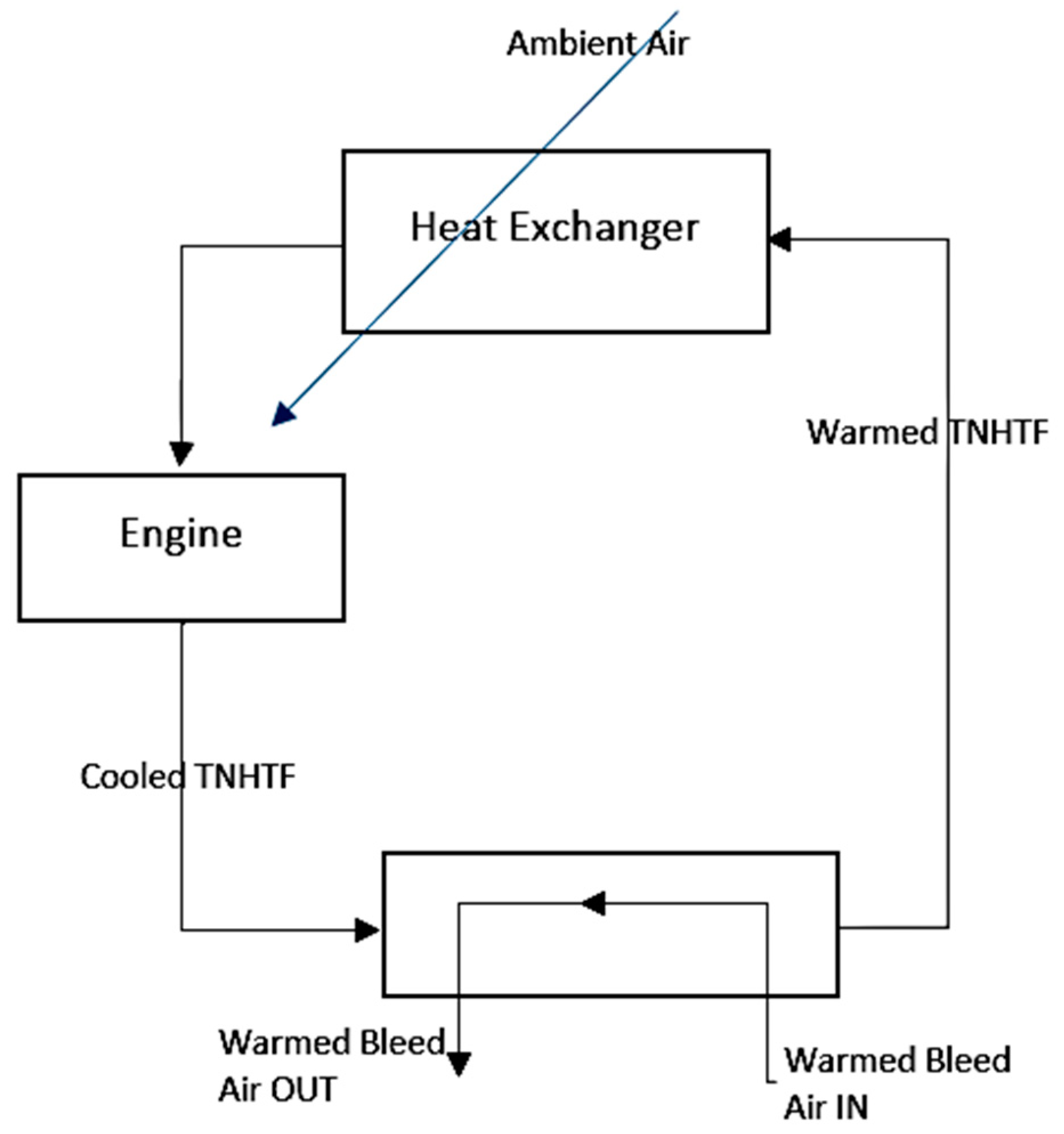
- Using different coolants (e.g., water, Therminol and thermally neutral heat transfer fluid (TNHTF)) to manage the thermal loads in different points of the gas turbine engine.
5. TMS Design Challenges and Potential Solutions for the Next Generation of Aircraft Engines
- Class I. Classic Development. This class of development would concentrate on the improvement of conventional TMS structure (Figure 1) for GTEs. This improvement could be applied on minor system structure changes in order to get better efficiency, replacement of the components with more advanced and smart ones (e.g., new, effective heat exchangers [59,60]) and changing the oil and fuel path to get better thermal management efficiency. The advantages of this approach are that the theoretical fundamentals and the implementation infrastructures are well-developed and these modifications would not dictate huge cost to manufacturers. However, the main disadvantage of this approach is that probably it would just bring marginal improvement for the TMS as this area is already well investigated.
- Class II. Centralized Development. This class would investigate the integrated TMS for the engine and airframe. It results in a centralized system that manages the thermal loads of the airframe and the engine simultaneously. So, the control algorithm and strategy would have more degree of freedom to deal with thermal loads. However, the main disadvantage is that it would be a high dimension multidisciplinary design problem with many parameters to select and tune simultaneously. Especially, in new advanced aircraft and engines it could be hardly affordable.
- Class III. Revolutionary Development. This class of development would cover new ideas with major changes in the TMS. Using new coolants for the engine ([50] and Figure 7) and ACC system ([35] and Figure 2) are examples of this class. The positive points about this class of development is that it may be possible to get a noticeable jump in TMS effectiveness. In other words, a revolutionary approach may result in a revolutionary achievement. But, the problem with this class of development is that implementation of these approaches requires a significant change in the system manufacturing and infrastructures and it may not be interesting for the airliners and manufacturers.
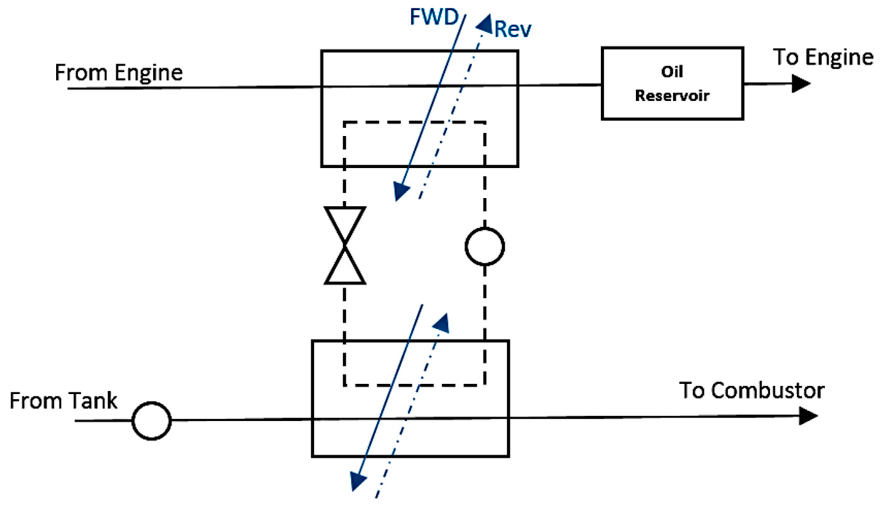
- Class IV. Cost-effective Development. This type of approaches will focus on the cost-effective solutions to enhance the TMS behaviour in the GTEs. The driving idea is to keep the hardware structure of the TMS unchanged (if possible) and to work on the solutions that could be implemented easily and/or with minimum changes in the current working systems. Enhancement of the control algorithms [61], splitters, valves and mixers [62] are some examples of cost-effective solutions. The relative merits of this class to the other classes is clear as the cost consideration is one of the most important issues in real-world applications. However, the correlation between the complexity and impact is the matter that should be discussed in these methods.
- (1)
- The first effective solution could be utilizing both class I and IV simultaneously. It means that concentration of new studies should be on some minor modification on the hardware as well as working on algorithms and strategies. The superposition of these classes of development would enable the TMS designers to deal with several challenges in parallel. In one hand, the main architecture of the TMS would be kept approximately unchanged as the manufacturers and airliners prefer. On the other hand, minor changes in the components and cooling paths will give a huge degree of freedom to the control structure designers to play with more parameters in order to enhance the performance indices of the TMS and the engine noticeably. As an illustrative example, change the circulation path of the oil in parallel with defining a smart control algorithm for the variable valve positions may result in a noticeable enhancement in the TMS performance.
- (2)
- Another solution could be defining the classes II and III as a unique approach in an engineering optimization problem format. The main idea would be to define the structure of the integrated TMS, the order of components, the oil and fuel paths, the air flowrate and path and so forth, as the indices of a comprehensive objective function; then to use a powerful optimizer to deal with the defined objective function. By tuning the mutation operator probability, the potential evolutionary developments would be investigated as well. However, definition of very smart constraints, penalty functions, penalty factors and objective function indices coefficients is a very vital step in successfulness of this approach. So, the main step in this solution is to define the problem statement very clear and with high level of details and accuracy; and then to select a suitable optimizer which can deal with such a big optimization problem with affordable run time.
- Class I. Classic development is a straightforward approach with low complexity. However, it is not expected that it could have a great impact on TMS efficiency for the future engines.
- Classes II and III. Centralized and revolutionary developments are complicated approaches in formulation and implementation. If they are successful, they would impact the TMS sector noticeably.
- Class IV. Cost-effective development is also directed towards design and implement and if the basic idea has great potential, the impact would be noticeable as well.
- (1)
- Solution I will promote the effectiveness of class I by combining it with class II of development
- (2)
- Solution II will promote classes II and III to achieve more impact to the TMS development in aerospace sector.
6. Conclusions
- (1)
- Combination of classes I (classic) and IV (cost-effective) to cope with much more extra heat generated by new advanced and geared turbofan engines with power gearbox,
- (2)
- Combination of classes II (centralized) and III (revolutionary) to deal with needs for energy management in the system and focusing on new smart components for more advanced smart thermal management systems.
Author Contributions
Funding
Conflicts of Interest
References
- Darecki, M.; Edelstenne, C.; Enders, T.; Fernandez, E.; Hartman, P.; Herteman, J.P.; Kerkloh, M.; King, I.; Ky, P.; Mathieu, M.; et al. Flightpath 2050, Europe’s Vision for Aviation Maintaining Global Leadership & Serving Society’s Needs; Report of the High Level Group on Aviation Research, Directorate-General for Research and Innovation Directorate-General for Mobility and Transport; Publications Office of the European Union: Brussels, Belgium, 2011. [Google Scholar]
- Han, J.C. Recent Studies in Turbine Blade Cooling. Int. J. Rotat. Mach. 2004, 10, 443–457. [Google Scholar] [CrossRef]
- Xu, L.; Bo, S.; Hongde, Y.; Lei, W. Evolution of Rolls-royce Air-cooled Turbine Blades and Feature Analysis. Procedia Eng. 2015, 99, 1482–1491. [Google Scholar] [CrossRef]
- Sunden, B.; Xie, G. Gas Turbine Blade Tip Heat Transfer and Cooling: A Literature Survey. Heat Transf. Eng. 2010, 31, 527–554. [Google Scholar] [CrossRef]
- Zheng, H.; Qi, L.; Zhao, N.; Li, Z.; Liu, X. A Thermodynamic Analysis of the Pressure Gain of Continuously Rotating Detonation Combustor for Gas Turbine. Appl. Sci. 2018, 8, 535. [Google Scholar] [CrossRef]
- Anindya, G.; Muthuvel, M.; Michael, J.W.; Andy, N.; Blake, D.B.; Marc, S.P.; Jeffrey, J.S.; Dongming, Z.; Kevin, A.K.; Christopher, R.R.; et al. Molten Particulate Impact on Tailored Thermal Barrier Coatings for Gas Turbine Engine. J. Eng. Gas Turbines Power 2017, 140, 022601. [Google Scholar] [CrossRef]
- Jafari, S.; Dunne, J.F.; Langari, M.; Yang, Z.; Pirault, J.-P.; Long, C.A.; Thalackottore Jose, J. A review of evaporative cooling system concepts for engine thermal management in motor vehicles. Proc. Inst. Mech. Eng. Part D 2016, 231, 1126–1143. [Google Scholar] [CrossRef] [Green Version]
- Lu, G.; Wang, F.; Di Mare, L.; Moss, M.; May, G. Data re-use for preliminary thermal-mechanical design of gas turbine engines. Aeronaut. J. 2018, 122, 462–486. [Google Scholar] [CrossRef]
- Gupta, M.; Markocsan, N.; Rocchio-Heller, R.; Liu, J.; Li, X.H.; Östergren, L. Failure Analysis of Multilayered Suspension Plasma-Sprayed Thermal Barrier Coatings for Gas Turbine Applications. J. Therm. Spray Technol. 2018, 27, 402–411. [Google Scholar] [CrossRef] [Green Version]
- Ma, X.; Ruggiero, P. Practical Aspects of Suspension Plasma Spray for Thermal Barrier Coatings on Potential Gas Turbine Components. J. Therm. Spray Technol. 2018, 27, 591–602. [Google Scholar] [CrossRef]
- Jafari, S.; Dunne, J.F.; Langari, M.; Yang, Z.; Pirault, J.P.; Long, C.A.; Thalackottore Jose, J. Control of Spray Evaporative Cooling in Automotive Internal Combustion Engines. J. Therm. Sci. Eng. Appl. 2018, 10, 041011. [Google Scholar] [CrossRef]
- Ljubas, D.; Krpan, H.; Matanovic, I. Influence of engine oils dilution by fuels on their viscosity, flash point and fire point. NAFTA 2010, 61, 73–79. [Google Scholar]
- Whurr, J. Future Civil Aero-engine Architectures & Technologies. In Rolls-Royce Future Programmes Report; Rolls-Royce PLC: Derby, UK, 2013. [Google Scholar]
- Spittle, P. Gas turbine technology. Phys. Educ. 2003, 38, 504. [Google Scholar] [CrossRef]
- Wang, Y.; Shah, N.; Huffman, G.P. Pure Hydrogen Production by Partial Dehydrogenation of Cyclohexane and Methylcyclohexane over Nanotube-Supported Pt and Pd Catalysts. Energy Fuels 2004, 18, 1429–1433. [Google Scholar] [CrossRef]
- Ganev, E.; Koerner, M. Power and Thermal Management for Future Aircraft; 13ATC-0280; SAE Technical Paper 2013-01-2273; SAE: Warrendale, PA, USA, 2013. [Google Scholar]
- Cumpsty, N. Jet Propulsion: A Simple Guide to the Aerodynamic and Thermodynamic Design and Performance of Jet Engines; Cambridge University Press: Cambridge, UK, 2012; ISBN 978-0-51-180941-5. [Google Scholar]
- Marshall, E.V. Oil Cooling and Drag Reducing System. U.S. Patent 2,865,530, 23 December 1958. [Google Scholar]
- Cummings, R.; Berea, L.; George, M. Engine Lubricating Oil Cooling Systems for Turbojets or the Like. U.S. Patent 3,080,716, 12 March 1963. [Google Scholar]
- Noddings, C.R.; Kelly, J.A. Endothermic Fuel System for Air Breathing Aircraft. U.S. Patent 3,438,602, 15 April 1969. [Google Scholar]
- Lavash, J.P. Fuel Delivery and Control System for a Gas Turbine Engine. U.S. Patent 3,779,007, 18 December 1973. [Google Scholar]
- Coffinberry, G.A.; Kast, H.B. Oil Cooling System for a Gas Turbine Engine. U.S. Patent 4,020,632, 3 May 1977. [Google Scholar]
- Frosch, R.A. Cooling System for High Speed Aircraft. U.S. Patent 4,273,304, 16 June 1981. [Google Scholar]
- Mayer, A.O.H. Heat Management System for Aircraft. U.S. Patent 4,505,124, 19 March 1985. [Google Scholar]
- Cornell, R.W.; Rohrbach, C. Multi-Bladed High Speed Drop Fan. U.S. Patent 4,171,183, 16 October 1979. [Google Scholar]
- Burr, D.N.; Danilowicz, P.S.; Franz, T.C.; Mortimer, T.P.; Pew, E.B. Fuel and Oil Heat Management System for a Gas Turbine Engine. U.S. Patent 4,696,156, 29 September 1987. [Google Scholar]
- Elovic, E. Cooling Air Cooler for a Gas Turbofan Engine. U.S. Patent 4,254,618, 10 March 1981. [Google Scholar]
- Griffin, J.G.; Schwarz, F.M. Cooling System for the Electrical Generator pf a Turbofan Gas Turbine Engine. U.S. Patent 4,474,001, 2 October 1984. [Google Scholar]
- Mortimer, T.P.; Suciu, G.L. Heat Exchange System. U.S. Patent 4,546,605, 15 October 1985. [Google Scholar]
- Hudson, W.A.; Levin, M.L. Integrated Aircraft Fuel Thermal Management System. U.S. Patent 4,776,536, 11 October 1988. [Google Scholar]
- Dennison, W.T.; Brodell, R.F. Nose Cowl Mounted Oil Lubricating and Cooling System. U.S. Patent 4,722,666, 2 February 1988. [Google Scholar]
- Geidel, H.; Rohra, A. Propfan Turbine Engine. U.S. Patent 4,887,424, 19 December 1989. [Google Scholar]
- Riid, K.; Rohra, A. Turbo Engine. U.S. Patent 4,999,994, 19 March 1991. [Google Scholar]
- Edwards, W.H. Inhibiting Coke Formation by Coating Gas Turbine Elements with Alumina. U.S. Patent 5,264,244, 23 November 1993. [Google Scholar]
- Bruening, G.B.; Chang, W.S. Cooled cooling air systems for turbine thermal management. In Proceedings of the ASME International Gas Turbine & Aeroengine Congress & Exhibition, Indianapolis, IN, USA, 7–10 June 1999; ISBN 978-0-7918-7860-6. [Google Scholar]
- Huang, H.; Spadaccini, L.J.; Sobel, D.R. Fuel-cooled thermal management for advanced aero engines. In Proceedings of the ASME TURBO EXPO 2002, Amsterdam, The Netherlands, 3–6 June 2002; pp. 367–376. [Google Scholar]
- Ely, J.F.; Huber, M.L. NIST Standard Reference Database 4—NIST Thermo-Physical Properties of Hydrocarbon Mixtures; National Institute of Standards and Technology: Gaithersburg, MD, USA, 1990.
- Spadaccini, L.J.; Colket, M.B.; Marteney, P.J.; Roback, R.; Glickstein, M.R.; Stiles, A.B. Endothermic Fuel/Catalyst Development and Evaluation—Phase I; AFWRDC-TR-89-2141; United Technology Research Centre: East Hartford, CT, USA, 1993. [Google Scholar]
- Spadaccini, L.J.; Sobel, D.R.; Colket, M.B.; Marteney, P.J.; Glickstein, M.R. Endothermic Fuel/Catalyst Development and Evaluation Phases II, III and IV; AFWL-TR-91-2126; United Technology Research Centre: East Hartford, CT, USA, 1993. [Google Scholar]
- Sobel, D.R.; Spadaccini, L.J. Hydrocarbon Fuel Cooling Technologies for Advanced Propulsion. J. Eng. Gas Turbines Power 1997, 119, 344–351. [Google Scholar] [CrossRef]
- Kim, J.; Park, S.H.; Chun, B.H.; Kim, S.H.; Jeong, B.H.; Han, J.S. A Technical Review of Endothermic Fuel Use on High Speed Flight Cooling. J. Korean Soc. Propul. Eng. 2010, 14, 71–79. [Google Scholar]
- Mahefkey, T.; Yerkes, K.; Donovan, B.; Ramalingam, M.L. Thermal management challenges for future military aircraft power systems. In Proceedings of the Power System Conference, Reno, NV, USA, 2–4 November 2004. [Google Scholar]
- Ronald, S.B. Gas Turbine Heat Transfer: Ten Remaining Hot Gas Path Challenges. J. Turbomach. 2007, 129, 193–201. [Google Scholar]
- Adam, C.M.; Elena, G.; Dimitri, M. Thermal Management Modeling for Integrated Power Systems in a Transient, Multidisciplinary Environment. In Proceedings of the 45th AIAA/ASME/SAE/ASEE Joint Propulsion Conference & Exhibit, Denver, CO, USA, 2–5 August 2009. [Google Scholar]
- Federico, P. Gas Turbine Engine Thermal Management System; EP 2 587 024 A2; United Technologies Corporation: Hartford, CT, USA, 2012. [Google Scholar]
- Suciu, G.L.; Pickford, S.; Ackermann, W.A.; Snape, N.; Hipsky, H.W. Turbomachinery Thermal Management. U.S. Patent 2013/0259687 A1, 3 October 2013. [Google Scholar]
- Niggemann, R.E.; Ngyuyen, D. Thermal and Energy Management Method and Apparatus for an Aircraft. U.S. Patent 6,182,435 B1, 6 February 2001. [Google Scholar]
- Huang, H.; Kaslusky, S.E.; Tillman, T.G.; Sabatlno, D.R. System Method for Thermal Management. U.S. Patent 6,939,392 B2, 6 September 2005. [Google Scholar]
- Suciu, G.L.; Norris, J.W. Turbine Engine Rotor Stack. U.S. Patent 7,309,210 B2, 18 December 2007. [Google Scholar]
- Walter Smith, J. Systems and Methods for Thermal Management in a Gas Turbine Power Plant. U.S. Patent 8,534,044 B2, 17 September 2013. [Google Scholar]
- Sousa, J.; Villafañe, L.; Paniagua, G. Thermal analysis and modelling of surface heat exchangers operating in the transonic regime. Energy 2014, 64, 961–969. [Google Scholar] [CrossRef]
- Brandon Wayne, M. Gas Turbine Engine Thermal Management System. U.S. Patent 0,208,698 A1, 21 July 2016. [Google Scholar]
- Peltokoski, R. Heat Exchangers for Thermal Management Systems. European Patent EP 3 054 126 A1, 2 September 2016. [Google Scholar]
- Teicholz, M.D.; Stearns, E.K. Technique for Optimizing Engine Performance Using Fuel Temperature. U.S. Patent 0,332,743 A1, 17 November 2016. [Google Scholar]
- Bracey, M.J. Dynamic Modelling of Thermal Management System with Exergy Based Optimization. Master’s Thesis, Wright State University, Dayton, OH, USA, 2016. [Google Scholar]
- Sibilli, T. Heat Exchange System for a Power Gearbox, a Power Gearbox and a Turbo Engine with a Power Gear Box. European Patent EP3244039 A1, 22 June 2017. [Google Scholar]
- Pececnik, J. Oscillating Heat Pipe for Thermal Management of Gas Turbine Engines. U.S. Patent 2014/0165570 A1, 19 June 2014. [Google Scholar]
- Vaisman, I.; Gagne, S.T.; Burkholder, K. Thermal Management System Controlling Dynamic and Steady State Thermal Loads. U.S. Patent 2018/0045432 A9, 15 February 2018. [Google Scholar]
- Mossey, R. Innovations Drive Weight and Emission Reductions for Aircraft Engines, 14 June 2017. Available online: http://blog.parker.com/innovations-drive-weight-and-emission-reductions-for-aircraft-engines (accessed on 14 June 2017).
- Abraham Karam, M. Gas Turbine Engine with Air/Fuel Heat Exchanger. U.S. Patent 9,771,867 B2, 26 September 2017. [Google Scholar]
- Jain, N.; Hencey, B.M. Increasing Fuel Thermal Management System Capability via Objective Function Design. In Proceedings of the 2016 American Control Conference (ACC) Boston Marriott Copley Place, Boston, MA, USA, 6–8 July 2016. [Google Scholar]
- Parker White Paper, Selecting a Thermal Management System Supplier for Aerospace and Defence Applications, Posted by Aerospace Team on Tuesday, 29 August 2017. Available online: http://blog.parker.com/selecting-a-thermal-management-system-supplier-for-aerospace-and-defense-applications (accessed on 29 August 2017).
- Construction Industry Institute (CII). Research Summary 305-1; CII: Austin, TX, USA, 2015. [Google Scholar]
- Construction Industry Institute (CII). Research Report 305-11; CII: Austin, TX, USA, 2015. [Google Scholar]
- Cicmil, S.; Cooke-Davis, T.; Crawford, L.; Richardson, K. Exploring the Complexity of Projects: Implications of Complexity Theory for Project Management Practice; Project Management Institute: Newtown Square, PA, USA, 2009. [Google Scholar]


| Thrust (lbf) | Turbine Entry Temperature (°C) | Bypass Ratio | Turbine Blade Cooling Efficiency | |
|---|---|---|---|---|
| Phase I | ≤40,000 | ≤1200 | ≤5 | ≤0.55 |
| Phase II | 40,000–55,000 | 1200–1400 | 5–7.6 | 0.55–0.65 |
| Phase III | ≥55,000 | ≥1400 | ≥8 | ≥0.65 |
| Class of Development | Main Drawbacks | |
|---|---|---|
| I | Classic |
|
| II | Centralized |
|
| III | Revolutionary |
|
| IV | Cost-effective |
|
© 2018 by the authors. Licensee MDPI, Basel, Switzerland. This article is an open access article distributed under the terms and conditions of the Creative Commons Attribution (CC BY) license (http://creativecommons.org/licenses/by/4.0/).
Share and Cite
Jafari, S.; Nikolaidis, T. Thermal Management Systems for Civil Aircraft Engines: Review, Challenges and Exploring the Future. Appl. Sci. 2018, 8, 2044. https://doi.org/10.3390/app8112044
Jafari S, Nikolaidis T. Thermal Management Systems for Civil Aircraft Engines: Review, Challenges and Exploring the Future. Applied Sciences. 2018; 8(11):2044. https://doi.org/10.3390/app8112044
Chicago/Turabian StyleJafari, Soheil, and Theoklis Nikolaidis. 2018. "Thermal Management Systems for Civil Aircraft Engines: Review, Challenges and Exploring the Future" Applied Sciences 8, no. 11: 2044. https://doi.org/10.3390/app8112044
APA StyleJafari, S., & Nikolaidis, T. (2018). Thermal Management Systems for Civil Aircraft Engines: Review, Challenges and Exploring the Future. Applied Sciences, 8(11), 2044. https://doi.org/10.3390/app8112044