1. Introduction
Renewable energy has developed rapidly during the past decades, and its proportion in the total power generation has gradually increased. The share of renewable energy (wind and solar power, bioenergy, and geothermal power) in global primary energy is expected to increase from around 10% in 2019 to between 35% and 65% by 2050 in three different scenarios [
1].
Among the renewable energy family, wind and solar power seem especially promising. With increasing deployment and module efficiency for solar and by higher load factors and lower operating costs of wind, the levelized cost of electricity (LCOE) generated from wind and solar power has fallen significantly [
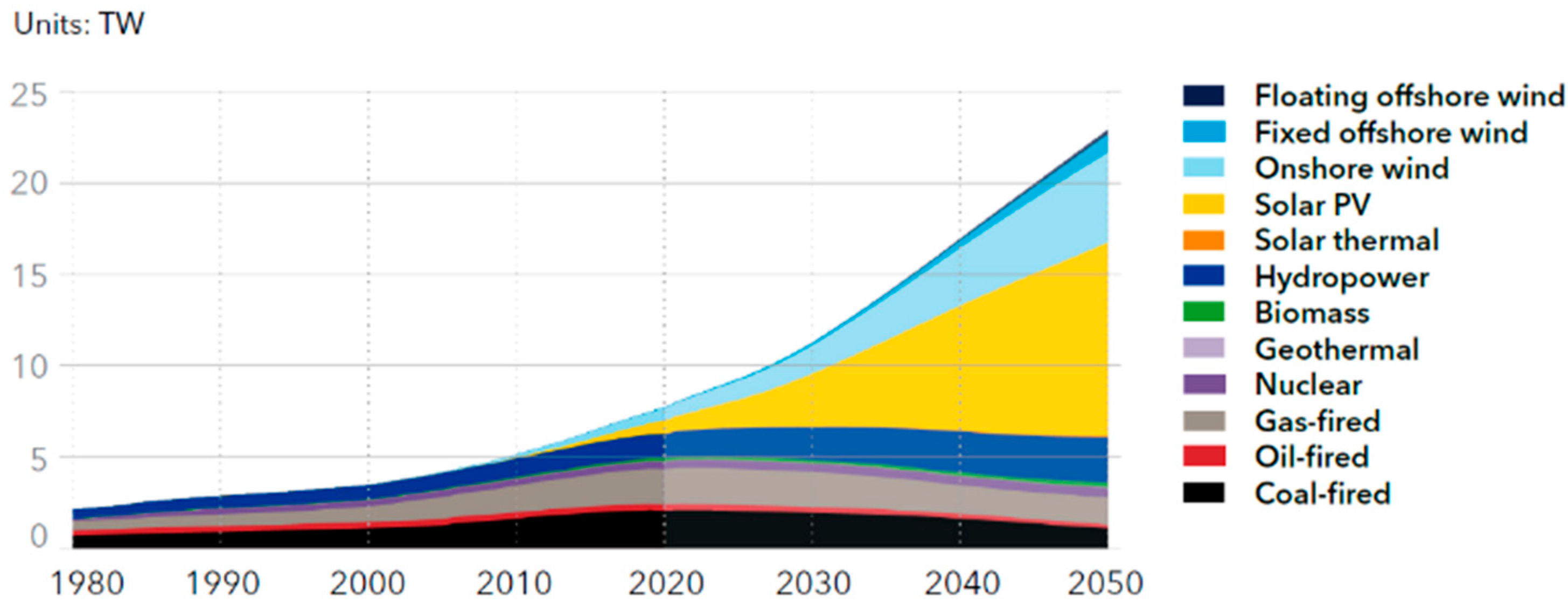
1]. Studies have shown that, in 2050, solar energy will serve a third of the world’s electricity demand [
2], as shown in
Figure 1.
Although the Capacity Factor of photovoltaics (PVs) may be lower compared to other renewable energy, such as hydroelectric plants, its other advantages, e.g., simple structure configuration, low development cost, and limited impact on the environment, has still accelerated its development globally. On the other hand, due to low PV panel efficiency (typically around 14%, which implies that a 1 MWp power station requires at least 15,000 m
2 of land), onshore PV may potentially occupy large areas of land that cannot be used for other purposes (agriculture, pasture, etc.). Combined with other potential risks, the onshore PV market may face a contraction in some areas, such as Europe and North America [
3].
Due to the above situation, in the past few years, FPV technologies, which install solar panels on floating platforms in the water, have become one of the most promising innovations and development directions. Compared with on-land PV, the FPV panels could be cooled down by the water, which may lead to a higher power generation efficiency. Moreover, the FPV plants are particularly suitable for areas with limited land areas but a high demand for electricity and water saving. Examples include irrigation reservoirs, hydroelectric dams, water treatment facilities, tailing ponds, and even aquaculture ponds. PV panels may also bring multiple benefits to these waters, such as reducing water eutrophication, inhibiting algae growth, protecting water sources, and making better use of water resources. Combining FPV power generation and hydropower generation to form a hybrid system has more advantages because it can make full use of existing power transmission infrastructure, be close to end users and markets, and increase power generation. Kim [
4] put forward an alternative based on flexible thin-film PV that floats directly on the waterline and concentrated on the techno-economic appraisal of offshore PV systems in comparison to conventional marine renewable energy technologies. Thin-film PV was found to be economically competitive with offshore wind energy projects at certain latitudes. The specific yield was higher for thin-film PV than for wind, wave, and tidal barrage systems. In addition, the specific installed capacity was also higher than those of the other conventional technologies considered (excluding tidal current turbines). Lin [
5] presented a new concept of conveying decommissioned FPSO as a platform for floating PV plants. The proposed PV system was designed to power offshore platforms or drilling rigs. Effects of tilt angle on energy outputs were evaluated through a frequency-domain hydrodynamic analysis of the FPSO. The results showed that roll motion has a larger negative effect on the total radiation on a collector, compared with pitch motion.
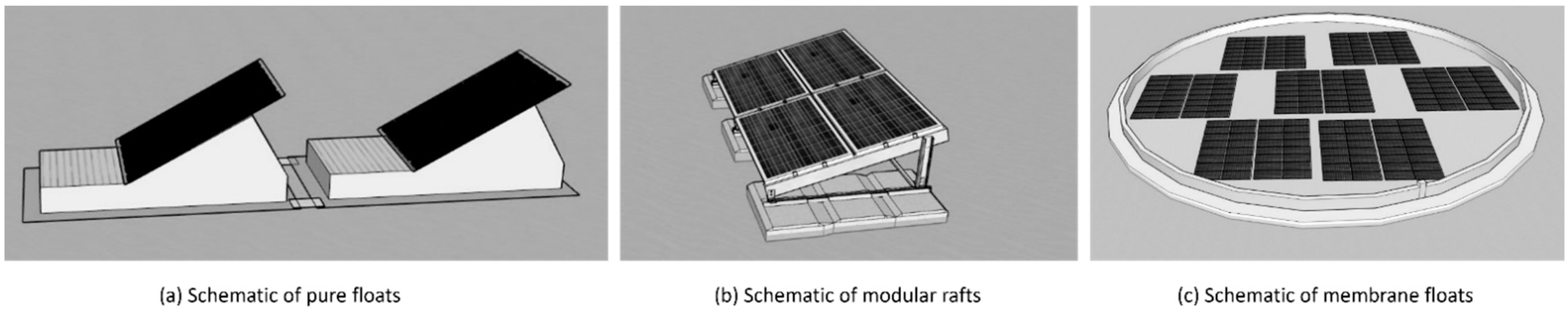
According to DNV-recommended practice, DNV-RP-0584, the most common FPV arrays are structurally defined into three main categories: (a) pure floats (or floats with PV modules), (b) modular rafts, and (c) membranes. See
Figure 2 [
6].
The first two types have similarities in terms of structure design and configurations, both of which include a large number of multiple floaters/modules linked by different kinds of connectors, whilst the third type has completely different structure characteristics. Patil [
7] and Yousuf [
8] gave reviews on floating solar photovoltaic power plants installed in the world and relevant technologies, showing the timeline of FPV concepts. These systems were either constructed for research purposes or for commercial use. All grid-connected systems are kept afloat using pontoons or floats with panels rigidly connected to these floats. However, it was also suggested to study optimization to improve the performance of FPV power plants. Choi [
9] presented the structural design for the development of the floating-type photovoltaic energy generation system using pultruded FRP members. In the design of the system, finite element analysis was conducted using the mechanical property data measured by experiment. Kim [
10] presented the design and construction process of a floating PV generation system with details of its actual construction. Moreover, they suggested the composition of the unit structure and the process for the construction of the large-scale floating PV generation complex. It was pointed out in the paper that for the commercialization of large-scale floating PV generation systems using FRP members, it may be necessary to develop appropriate elemental techniques, construction skills, mooring systems, etc. Friel [
11] outlined technological variations in conceptual and installed designs of FPV installations. The paper also presented various studies of floating solar floaters, in the aspects of hydrodynamics, aerodynamics, structural analysis, aero-hydro-elastic coupled analysis and design, performance, and feasibility. With the proprietary nature of the FPVs and as the technology is still in an early stage of development, the literature and technical data of designs and installations are very limited. Many of the studies reporting floating solar systems were conducted as a technical feasibility analysis for the assessment of electrical performance, and the optimization of efficiencies with cooling, tracking, and concentrating mechanisms. The study of Baderiya [
12] presented a preliminary mooring design method adapted to floating solar from a quasi-static perspective. It introduced a generic, analytical, and industry-used method to determine the loads due to waves, current, and wind on the floating island, and discussed the main design challenges for each case. Ikhennicheu [
13] presented three reference cases for floating solar farms. The aim was to present one of the methodologies currently used in industry to perform a mooring design and to highlight the areas where further research was necessary before continuing to develop industrial projects. The results showed that wind loads dominate for all cases, except for the offshore conditions, where waves have a significant contribution to the total load (around 50%).
As for now, it seems that the hydrodynamic analysis for a single floater and coupling effects with a large number of modules have not been studied thoroughly yet in the FPV industry, and neither has the analytic approaches for mooring design.
The main purpose of this paper is to study the feasibility and fidelity of different numerical approaches in application to the analysis of floating PV. As the starting point of a large research project, the conclusions of the paper are also meant to provide some initial guidelines of the methodologies for the follow-up numerical studies and possible model test validations.
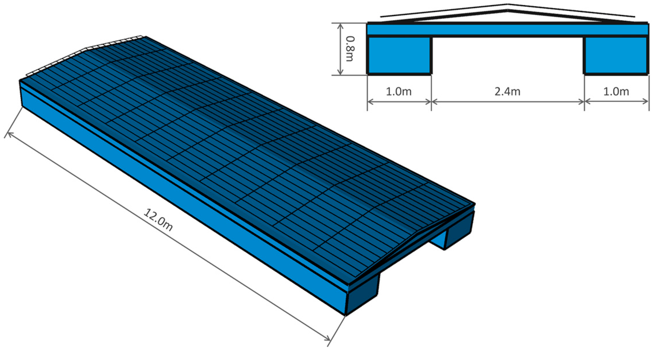
The paper is organized as follows. In
Section 2, the concept of the floating PV, including the main dimensions of the single module, as well as the array system, is introduced. The different hydrodynamic methods, as well as the damping model used in the calculation, are briefly explained in
Section 3.
Section 4 starts with the frequency domain analysis of a single floater module, and then introduces the time domain solver to check the nonlinear hydrodynamics due to the low draft and small airgaps in the free surface areas between the pontoons. A comparison of the frequency domain responses with different damping combinations and the time domain results is also conducted and some damping coefficients are suggested. With proper damping coefficients from the first part of the analysis, in
Section 5, a multi-body analysis is performed to check the hydrodynamic coupling. Also, a damping surface model is tested to obtain realistic responses of the system. Some further discussions of the hydrodynamic analysis are provided in
Section 6. And in
Section 7, time-domain-coupled analyses of a scaled-down system (with 9 modules and mooring lines) are conducted, followed by the building of a realistic FPV system (with 90 modules, 4 buoys, connectors, inner bridle lines, and mooring lines), and some preliminary results are presented. Finally, the main conclusions can be found in
Section 8.
3. Potential Analysis, Free Surface Damping, and Nonlinear Hydrodynamics
A general approach to simulate this complex system is to first obtain the hydrodynamic analysis for a single module, and later use it to set up the multibody system with connectors and mooring systems in a coupled analysis solver.
In the current paper, the main analysis is carried out by using a frequency domain potential solver [
14], whilst for the calibration purpose, which is explained a little bit later, a time domain potential solver [
15] is also used in some analyses.
The potential theory as described by Newman [
16] is applied to calculate first-order radiation and diffraction effects on large-volume structures. The implementation uses a 3D panel method to evaluate velocity.
The flow is assumed to be ideal and time-harmonic. The free surface condition is linearized for the first-order potential theory. The radiation and diffraction velocity potentials on the wet part of the body surface are determined from the solution of an integral equation obtained by using Green’s theorem with the free surface source potentials as the Green’s functions. The source strengths are evaluated based on the source distribution method using the same source potentials.
The assumption of potential flow allows for defining the velocity flow as the gradient of the velocity potential
that satisfies the Laplace equation in the fluid domain.
In the frequency domain, the harmonic time dependence allows for defining a complex velocity potential
related to
by
where
is the frequency of the incident wave and
t is time. The associated boundary-value problem is expressed in terms of the complex velocity potential
ϕ with the understanding that the product of all complex quantities with the factor
applies. The linearized form of the free-surface condition is
where
. The linearization of the problem permits the decomposition of the velocity potential
into the radiation
and diffraction
components.
Compared to traditional O&G floaters, as the floaters of the FPV system normally have a small size and free board, several aspects may bring nonlinearities during the hydrodynamic analysis and need thorough investigation.
First, considering the shape of the module, the viscous forces on the rectangular pontoons may occupy a large proportion of the total wave forces. Two alternatives may be used here to include the loads. It could be represented as (part of) the global damping matrix, whilst if a more accurate estimation is needed, an equivalent beam model could also be included with the loads calculated with Morison theory.
More complexity comes from the free surface elevation, which may cause the motion resonances of the modules. It is known that linear potential flow theory over-predicts the free surface elevations in a confined waterplane area, for example, the gap between two ship-hulls or the moon-pool area of a drilling ship. The main reason for the differences between the potential solver and the experimental results may come from the fact that the viscosity in the confined waterplane may dominate the surface elevation and forces, whilst it may not be able to be well predicted with conventional potential theory.
In addition, according to Vada [
17], the piston and sloshing modes may be excited in a resonance scenario of the moonpool. For a single FPV module, the area between the pontoons is relatively enclosed. It is also suspected that under certain wavelengths, these resonance modes may also be excited. In the O&G industry, this phenomenon has been observed for the semisubmersible platform, which has a similar shape configuration, although the latter has a much larger size.
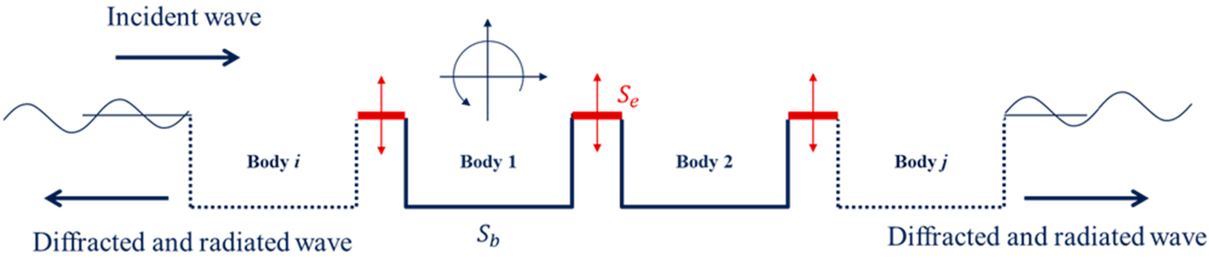
Similarly, when it comes to multibody analysis, if the viscous effect is ignored, it is difficult to estimate the motion of the free surface among bodies, especially if they are in a large number of module arrays. Under a certain wavelength and direction, large elevations, so-called “gap resonance”, may be expected from the pure potential analysis. Such resonance may lead to large motion responses of the floater in some degrees of freedom, which may further amplify the resonance of the system and cause unrealistic analytic results.
The viscous forces will in general dissipate energy, and hence both the gap surface elevation and body motions should be reduced.
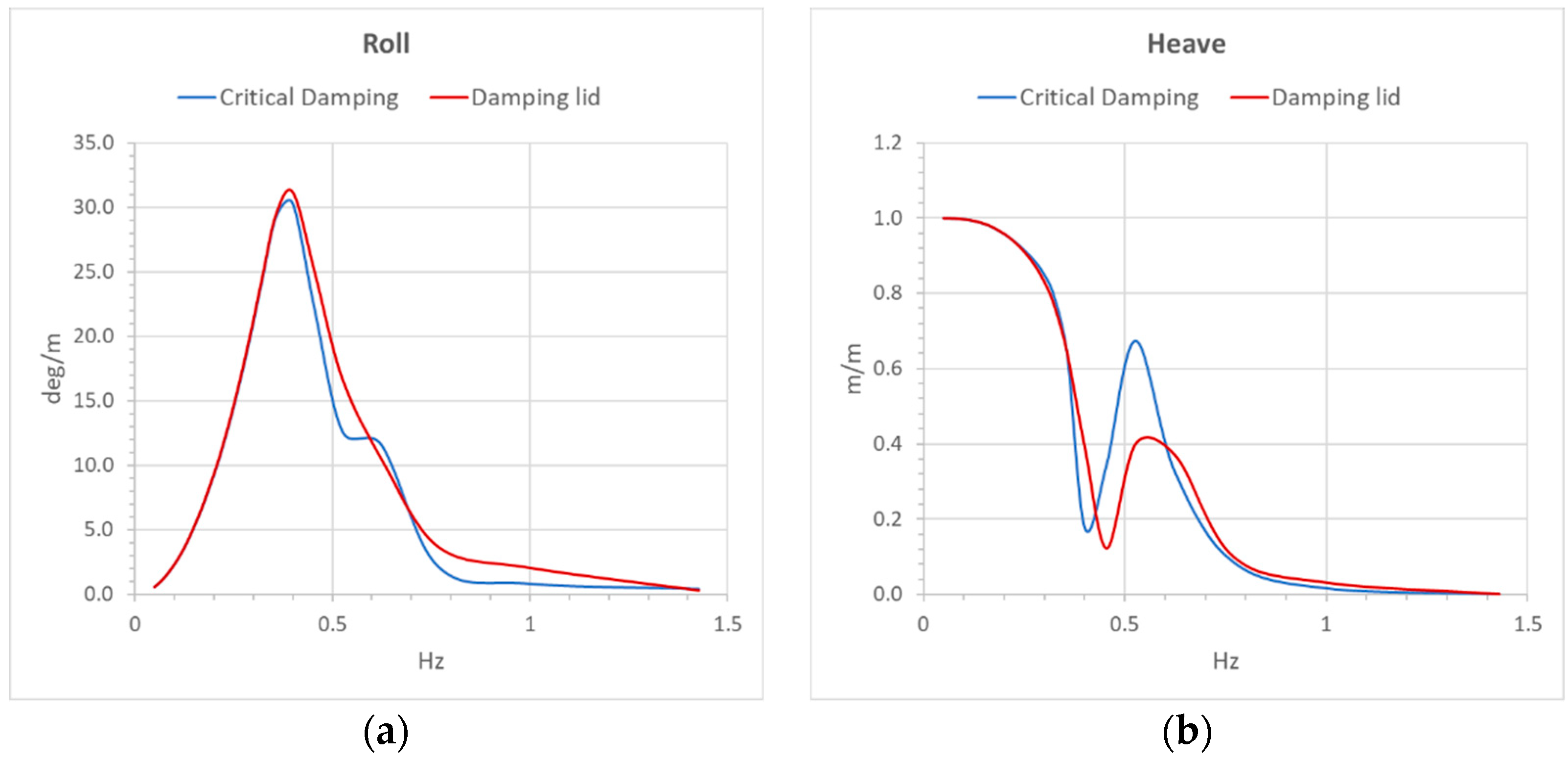
For the free surface damping model (which is also commonly referred to as the damping lid), many numerical and experimental studies have been conducted. Buchner [
18] developed a time domain simulation model to predict the responses of an LNG FPSO alongside a moored LNG carrier, in which an impermeable surface lid was used to calculate the drift forces. Chen [
19] introduced the multi-domain boundary element method (MDBEM) for bodies with a hull form including moonpools. The free surface damping was defined as proportional to the vertical displacement with opposite direction. In Markeng’s study [
20], the relevant potential theories were summarized and two damping models were discussed.
The pressure damping model, in which an artificial pressure is introduced as a real physical effect, with the purpose of reproducing the same energy input to the system as the viscous damping forces. As the added pressure terms have actual physical meaning, the advantage of this approach is that it is easier to obtain theoretical values. However, during the numerical solution, the corresponding velocity potential is a nonlinear term, and the use of iterative calculations poses a convergence challenge.
Another method has primarily been used in the context of numerical beaches, in which a dissipation term is introduced into the kinematic free surface condition; therefore, only incoming waves are present at the outer boundary of the gap areas.
To suppress the unrealistic free surface elevations with a panel model placed on the confined water-plane area, an imposed damping free surface condition is introduced as follows [
14]:
Comparing Equation (5) with (4), the additional terms with linear damping factor ϵ are added on the exterior free surface area .
The integral equation then becomes:
where
denotes the body mean wet surface. The Green function
represents the velocity potential at field point X due to a point source located at point
ξ.
Zhao [
21] compared the results of gap resonance analysis from several different solvers and provided a validation against the model test.
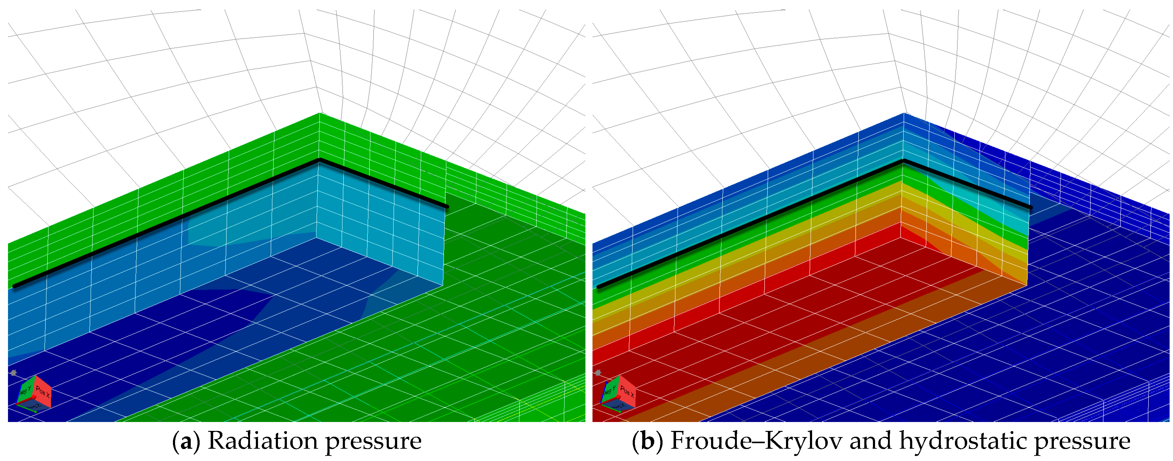
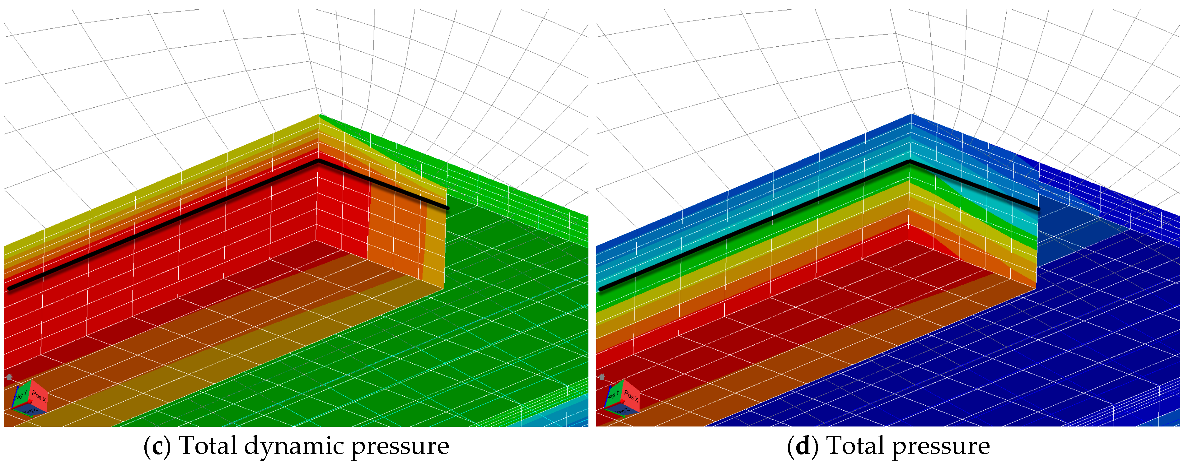
Due to the small size of the FPV modules, another consideration is the relatively large wet surface change, which may bring in wave impacts on the bottom and water on-deck. In such a scenario, the nonlinear effects may be very strong and difficult to estimate without model test results. Therefore, a nonlinear hydrodynamics code [
15] is also used in the paper to check those effects and validate additional damping coefficients from the linear frequency domain method.
5. Multiple-Module Hydrodynamic Analysis
Another aspect normally brought up for FPV analysis is the multibody coupling analysis.
Here, two kinds of coupling effects are actually of common interest. The first one is hydrodynamic coupling and the second is the mechanism connections among modules. Although it is possible to include the extra stiffness (and damping) between bodies in the hydrodynamic coupling analysis to represent the connectors, the multibody stiffness matrix will become prohibitively large and complex due to the large number of modules in FPV concepts; therefore, we only check the hydrodynamic coupling effects first and leave the modeling of connectors in the time domain system simulation to be discussed in a follow-up paper.
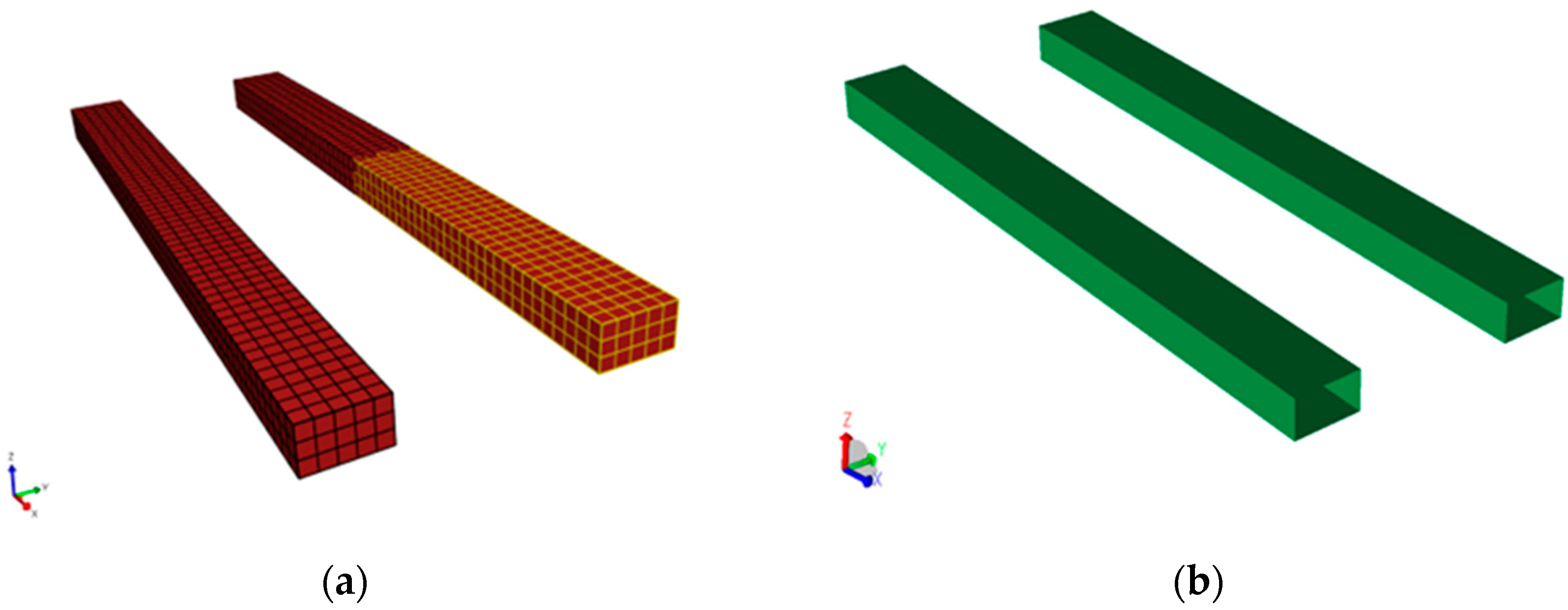
As shown in
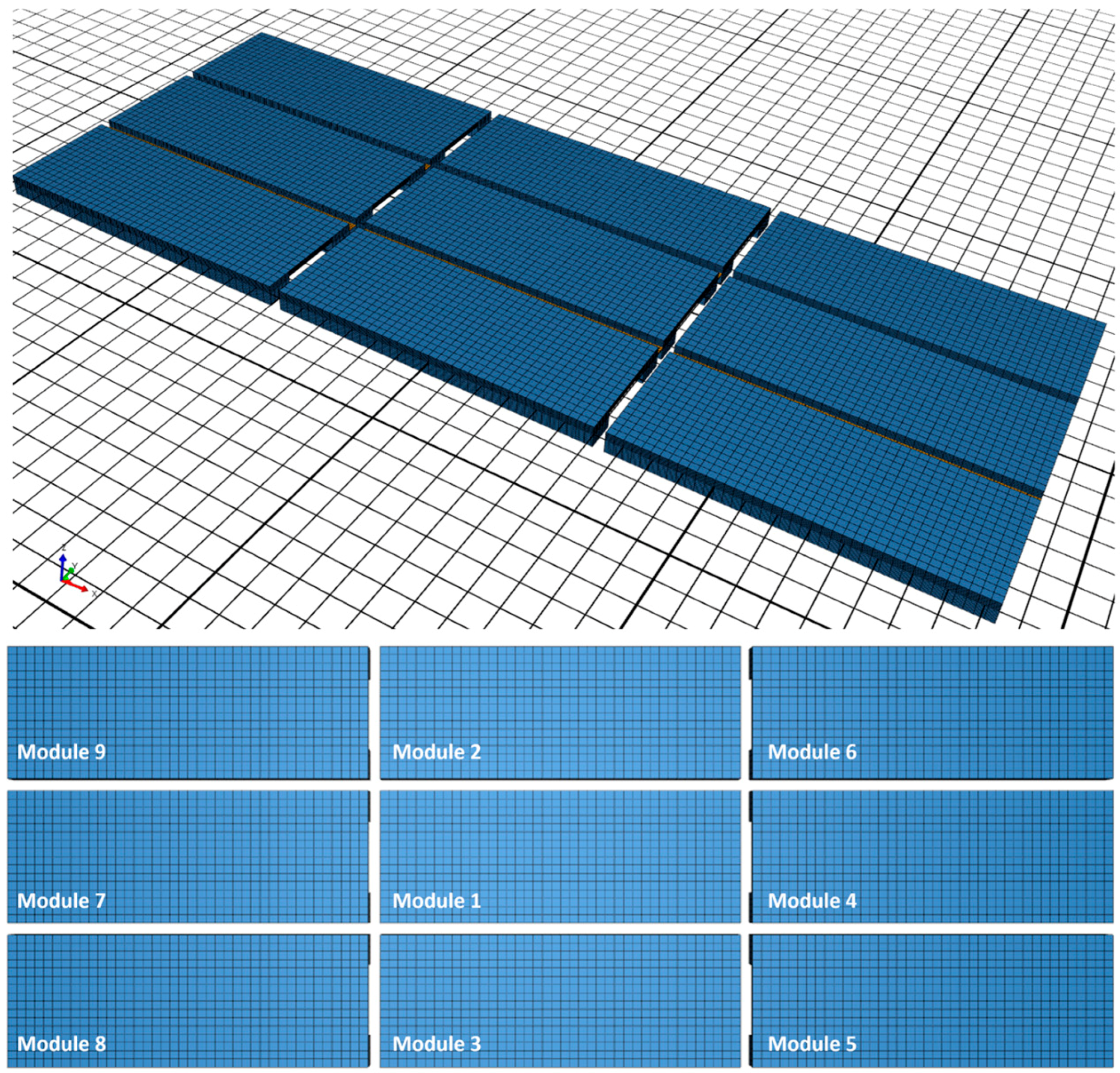
Figure 19, a system with a 3 × 3-module array is modeled, and the same critical damping coefficients from the previous study are specified for individual modules.
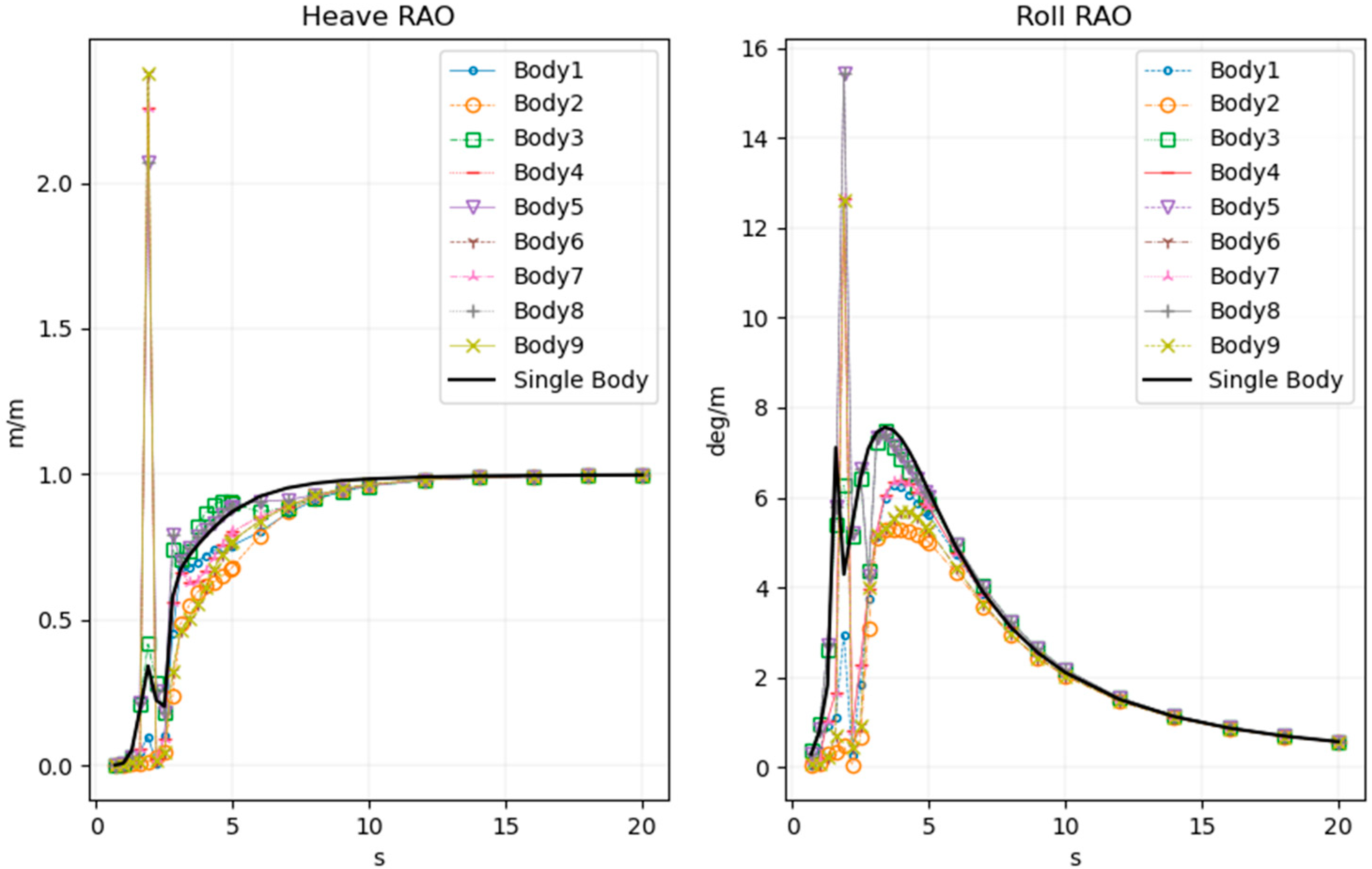
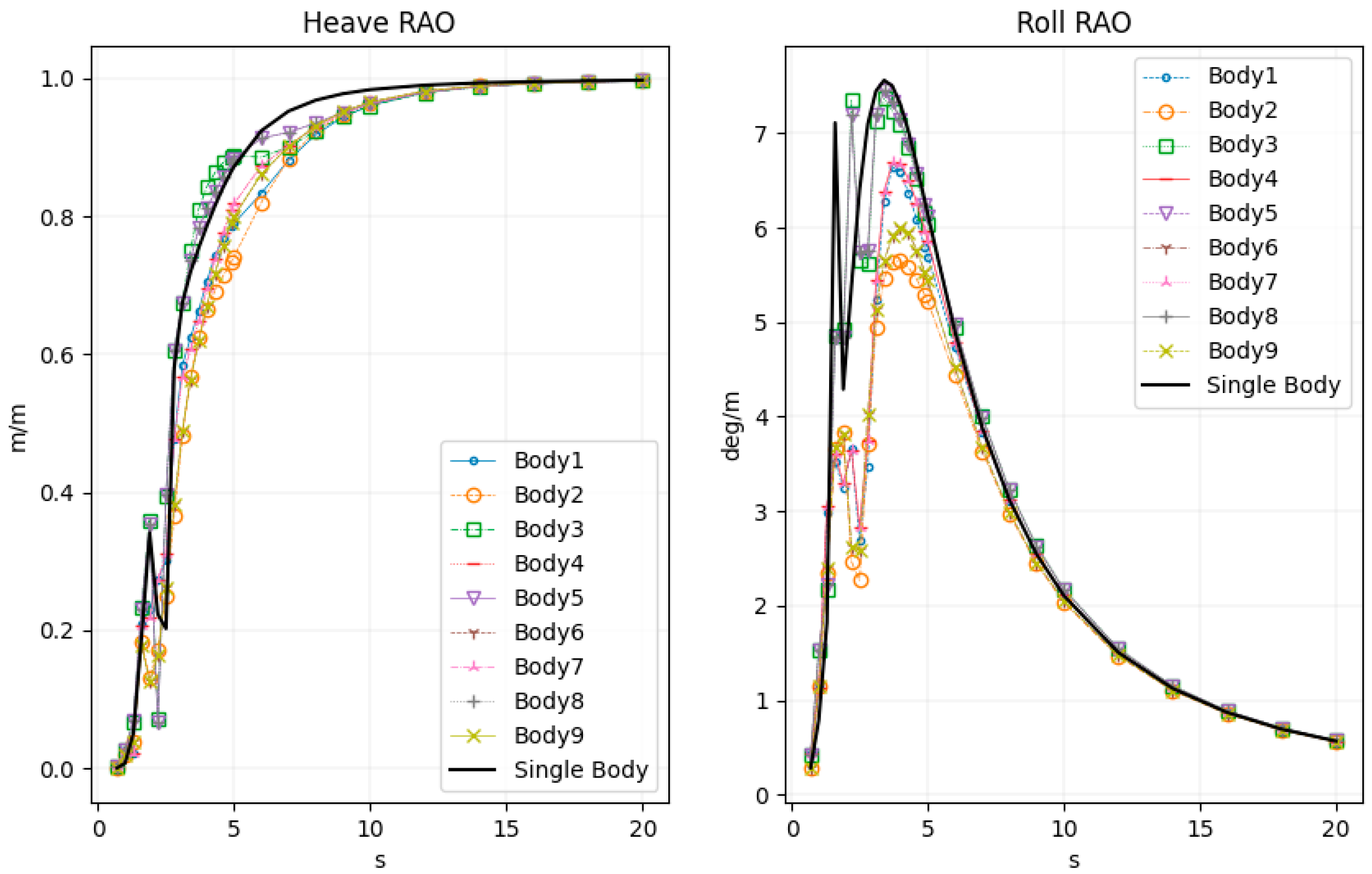
Figure 20 shows the results from the initial nine-body analysis. It is found that modules 1 and 2 have relatively small heave and roll motions, and module 3’s responses are close to the single-body analysis. This is understandable, considering that modules 1 and 2 may be “shadowed” by other modules. On the other hand, it is an interesting observation that the modules on the outer side of the array obtain quite large responses. They seem to be far more excited by the hydrodynamic coupling if we compare them with the single-body responses.
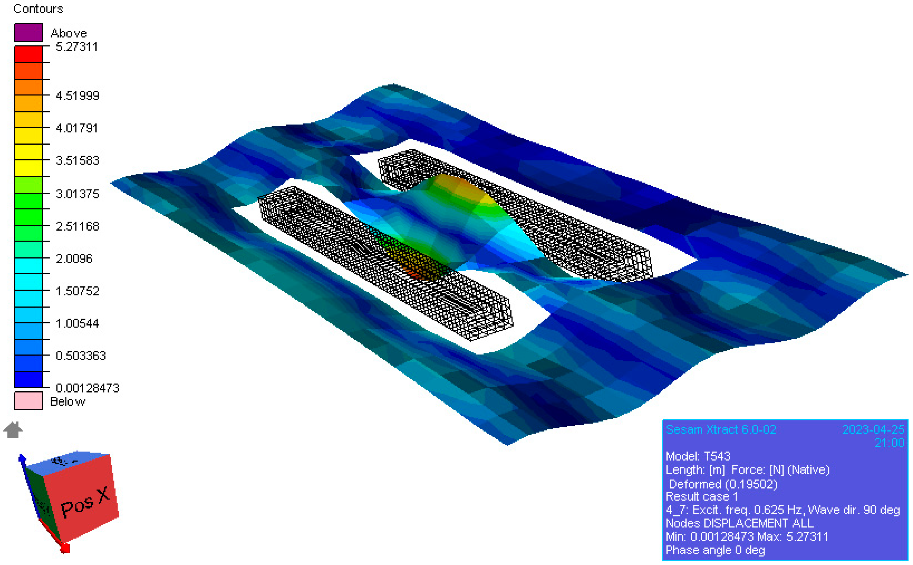
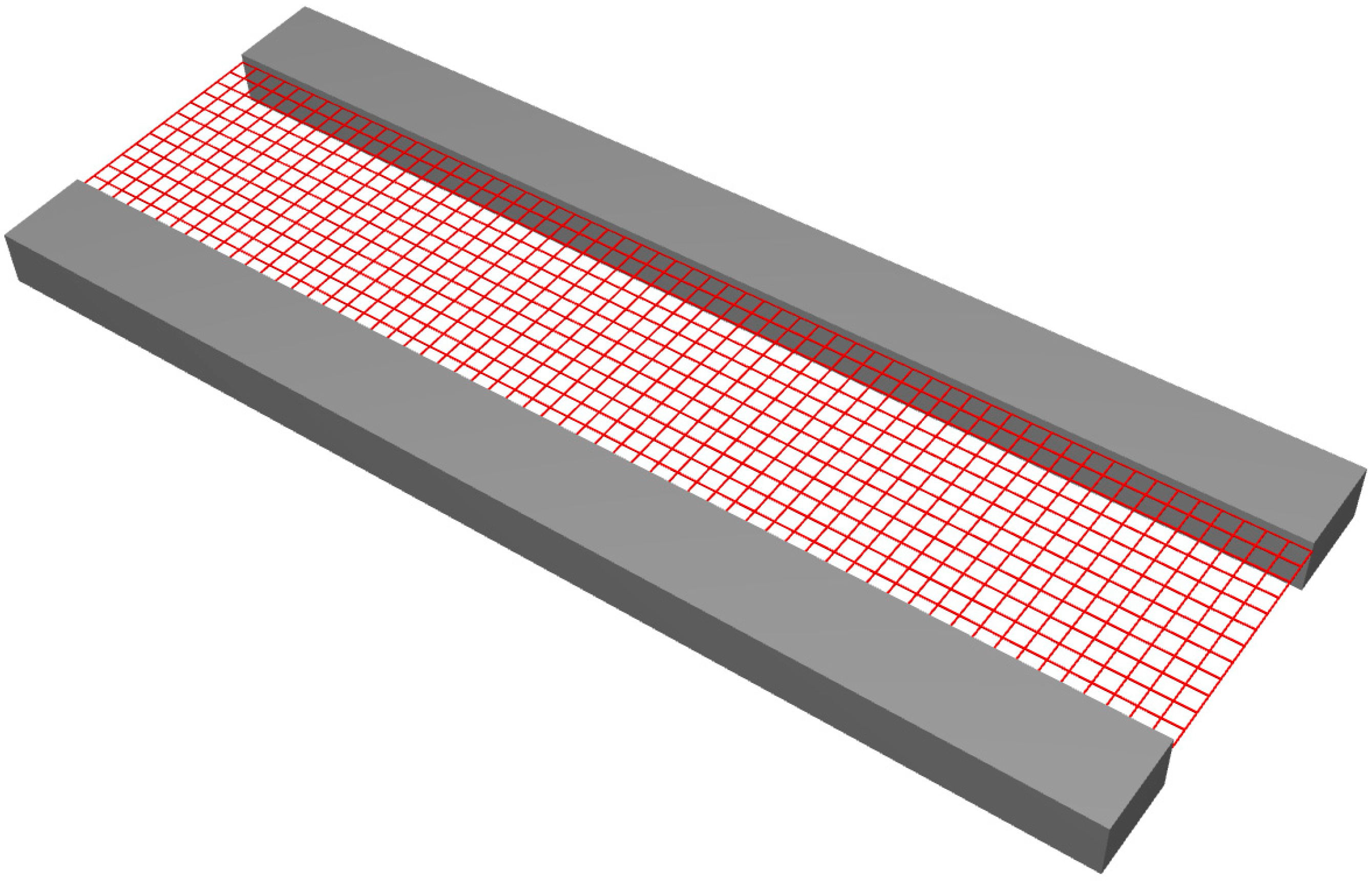
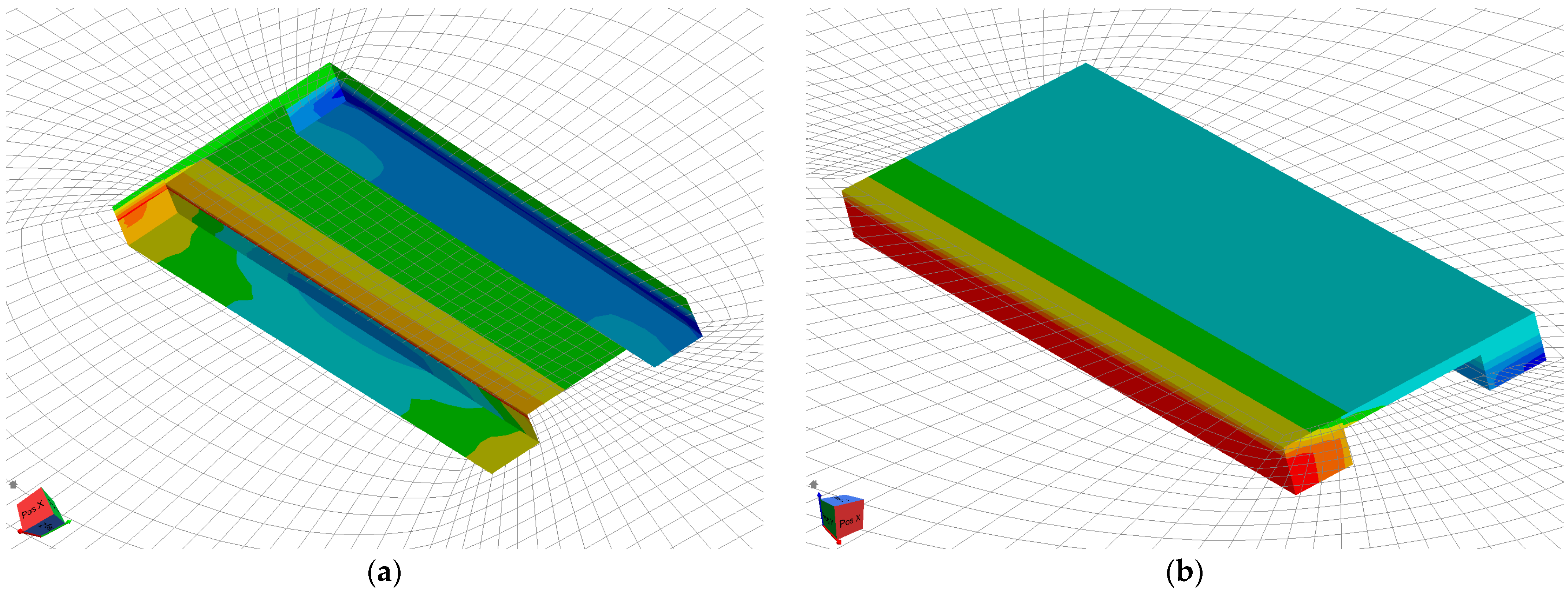
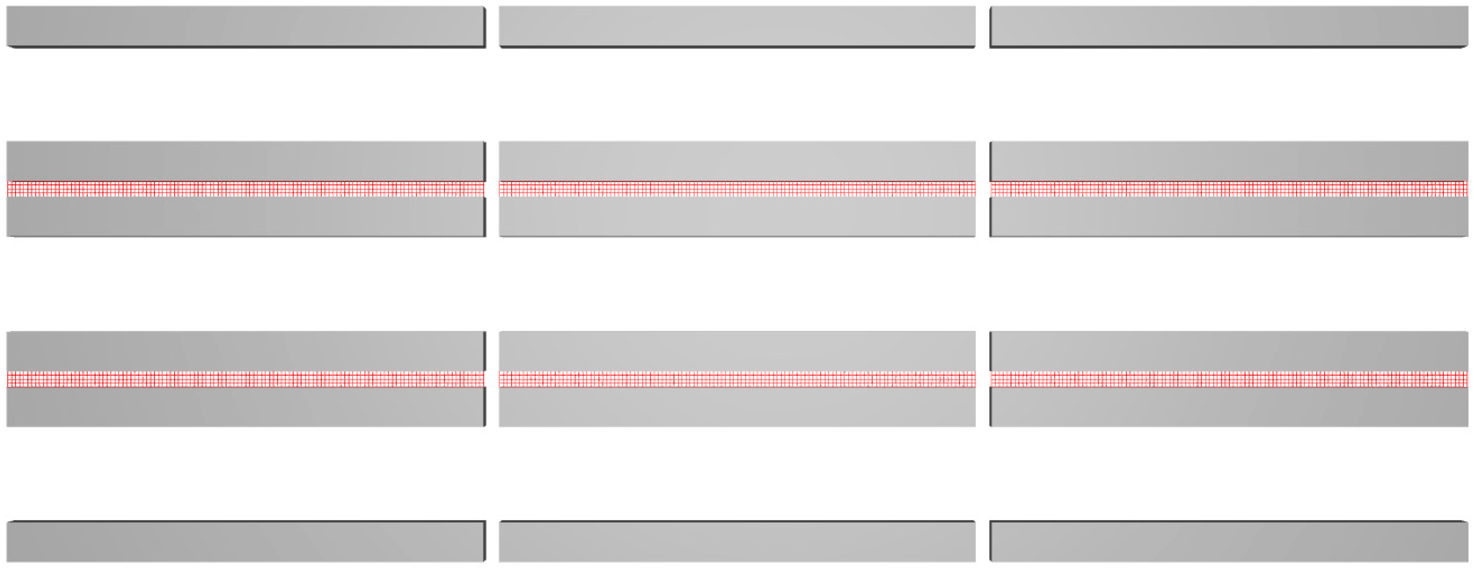
To further estimate the effects of the gaps among the modules, as shown in
Figure 21, a separate mesh model is placed between the gaps of the modules (the red mesh), and some damping is added. The results are shown in
Figure 22, which looks much more consistent.
6. Discussion of the Hydrodynamic Analysis
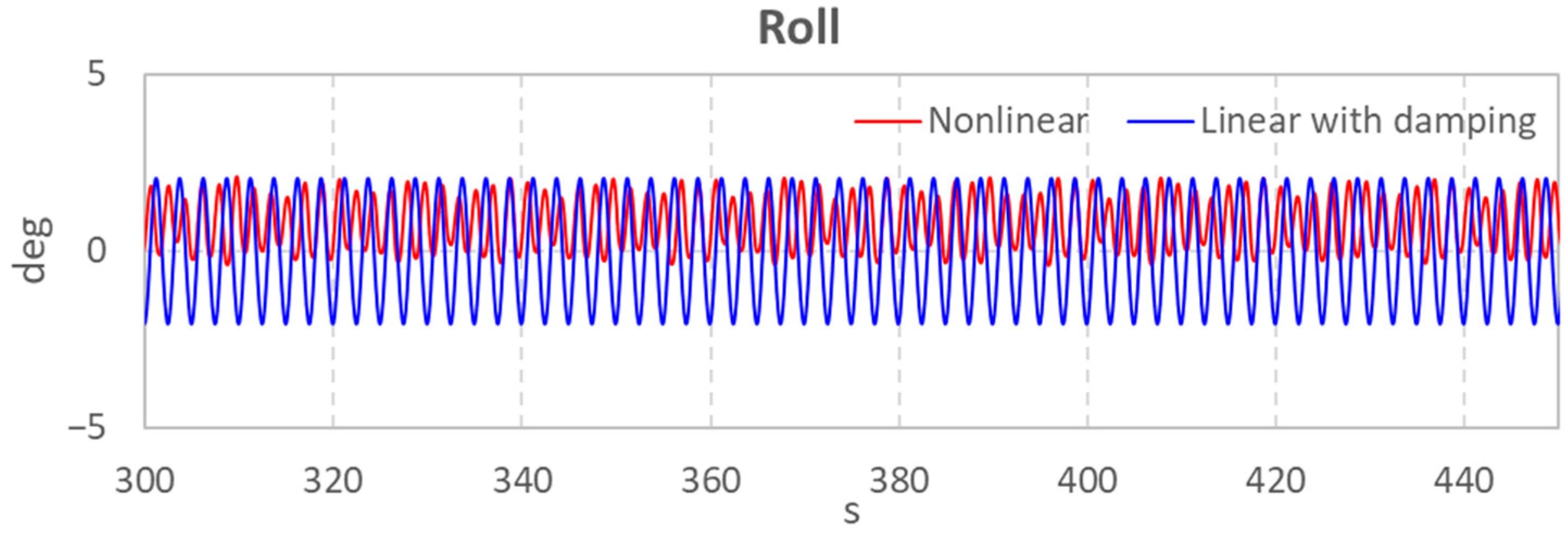
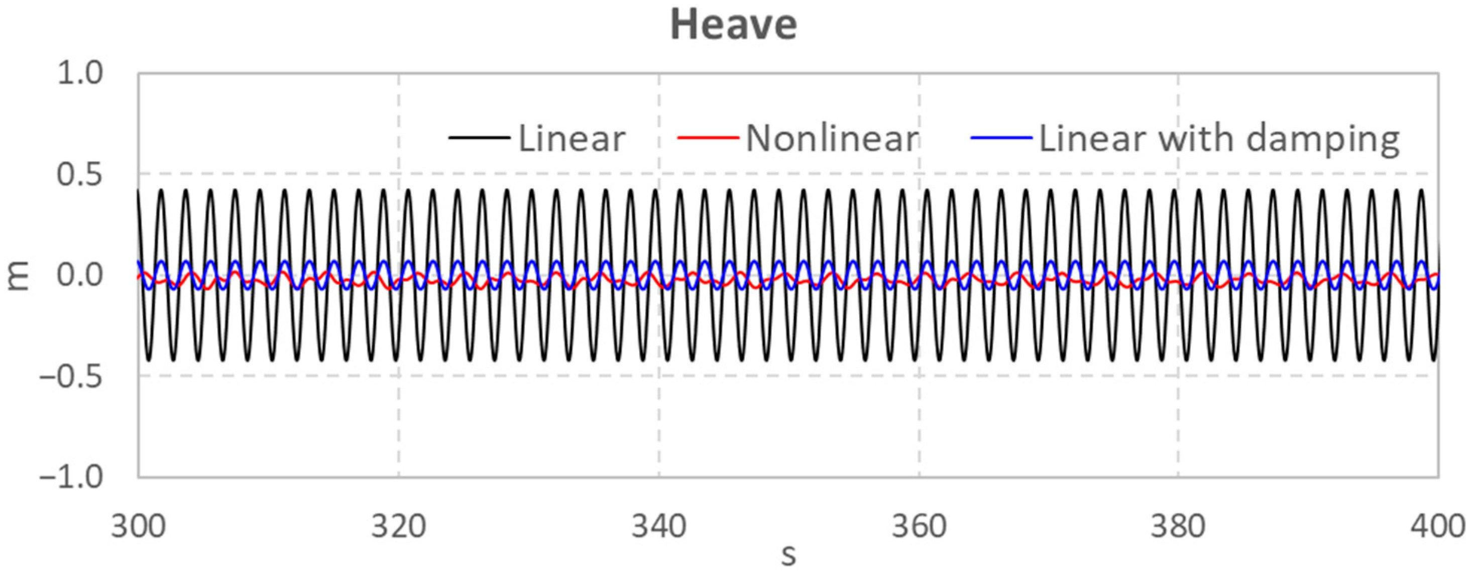
For this type of FPV (or similar design), the size of a single floater is relatively small. Due to the low freeboard and small air gaps in the area between the pontoons, a linear frequency domain approach may not easily provide realistic hydrodynamic results, even with an extra beam element calculated by Morison theory and/or damping coefficient with an empirical value from other industries. A resonance mode may be caused, which may bring in the wave impact on the bottom of the upper structure. For small waves, this might not be a concern for structure design, but it leads to unrealistic hydrodynamic coefficients, which makes the time domain system analysis (e.g., the mooring design) difficult. It is attempted to add some free surface damping, yet the outcome is not satisfactory.
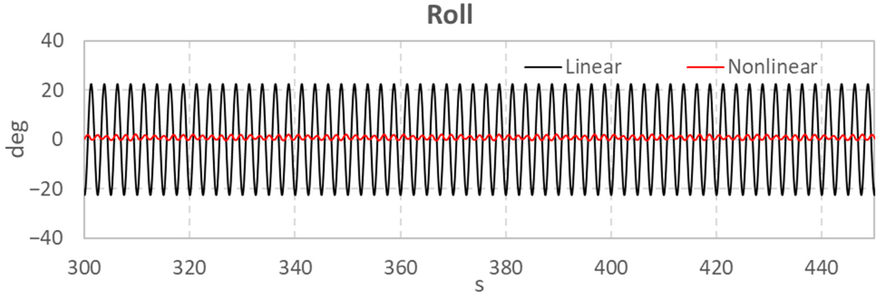
Without a model test, the nonlinear hydrodynamic solver in the time domain becomes important in this study. It is found that, to obtain a similar response of the nonlinear analysis, a damping coefficient that is much larger than empirical values may need to be specified. Nevertheless, this still provides the opportunity to obtain the hydrodynamic coefficients in an efficient way, considering the time consumption of a nonlinear approach.
For multibody analysis, some large motions of the modules may be observed on the outer areas of the FPV array, which potentially may be caused by the gap resonances. Free surface damping on those gap surfaces could obviously eliminate the unrealistic responses though.
Compared to the previous studies, this is the first attempt to apply different free surface damping models, as well as the nonlinear potential solver to a floater with a relatively small size, also with a large number of bodies. It seems that larger damping coefficients may be needed to obtain reasonable responses, compared to conventional O&G structures. In addition, the change in water surface may have larger impacts on the load calculation and consequently the motion prediction. This is understandable though considering the relative scale of FPV modules and the incoming wavelength even under the small wave height. The results could be further used and refined in the later model test validation.
7. Preliminary Coupled Analysis with Mooring System
Based on all the discussions above, some further studies are carried out to check the global performance and mooring system of the FPV system. It is not within the scope of this paper to present the simulation and results in detail, while some initial descriptions and outcomes are listed below.
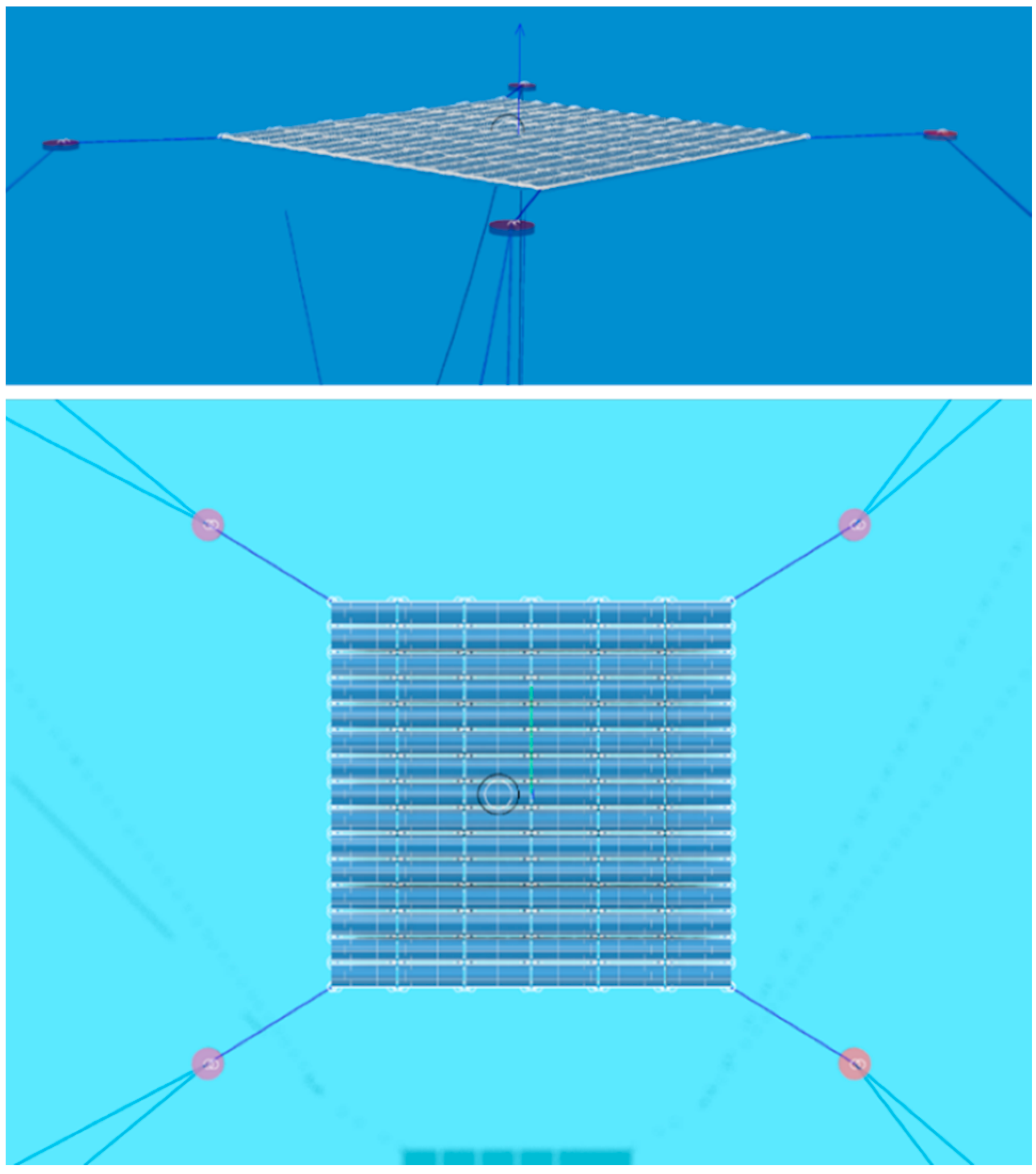
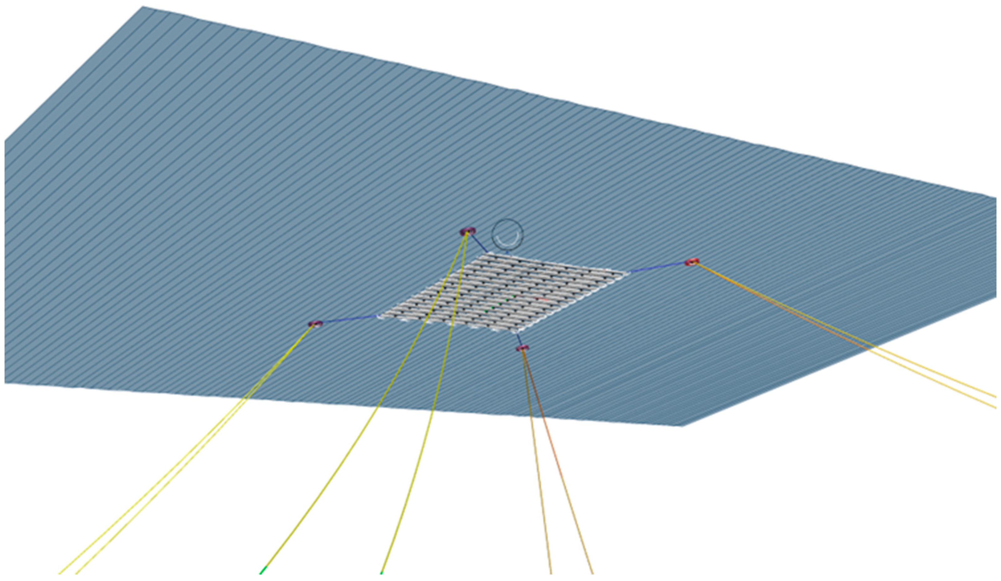
Corresponding to the hydrodynamic analysis, a simplified system with 9 modules and 4 mooring lines is first simulated to check the feasibility and convergence of the simulation, as shown in
Figure 23. Connectors between modules are modeled with nonlinear stiffness, and different numerical models and parameters are also tested.
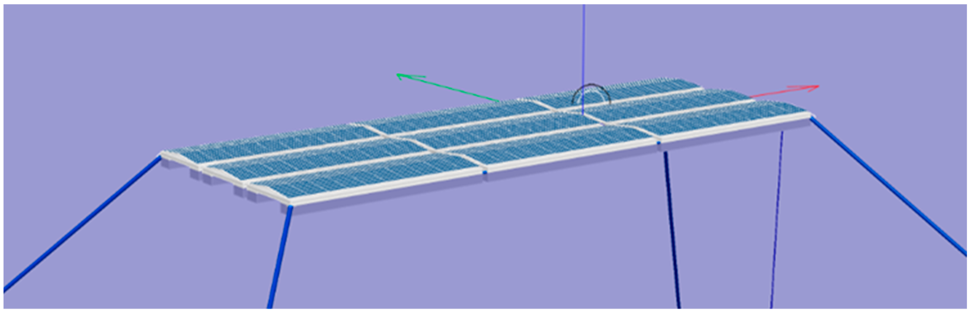
Based on the results from the simplified system, a complete system with 90 modules, 4 buoys, 4 connecting lines, and 8 mooring lines is built afterward, as shown in
Figure 24.
The environment conditions for the seastate used in the testing run are listed in
Table 6. The water depth for the example site is 300 m.
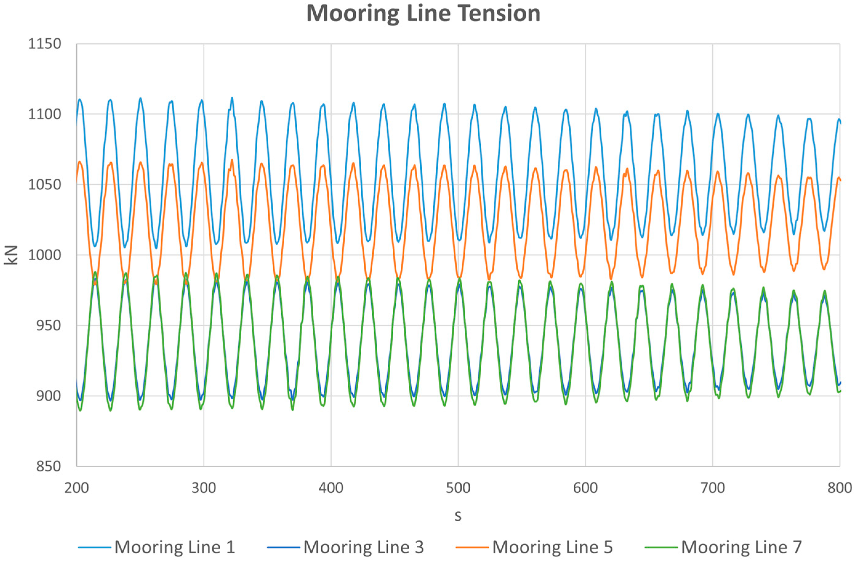
Figure 25 shows the mooring line tensions under an operation environment. In general, it seems the system is quite stable, and the tensions are well within design limits in the cases analyzed.
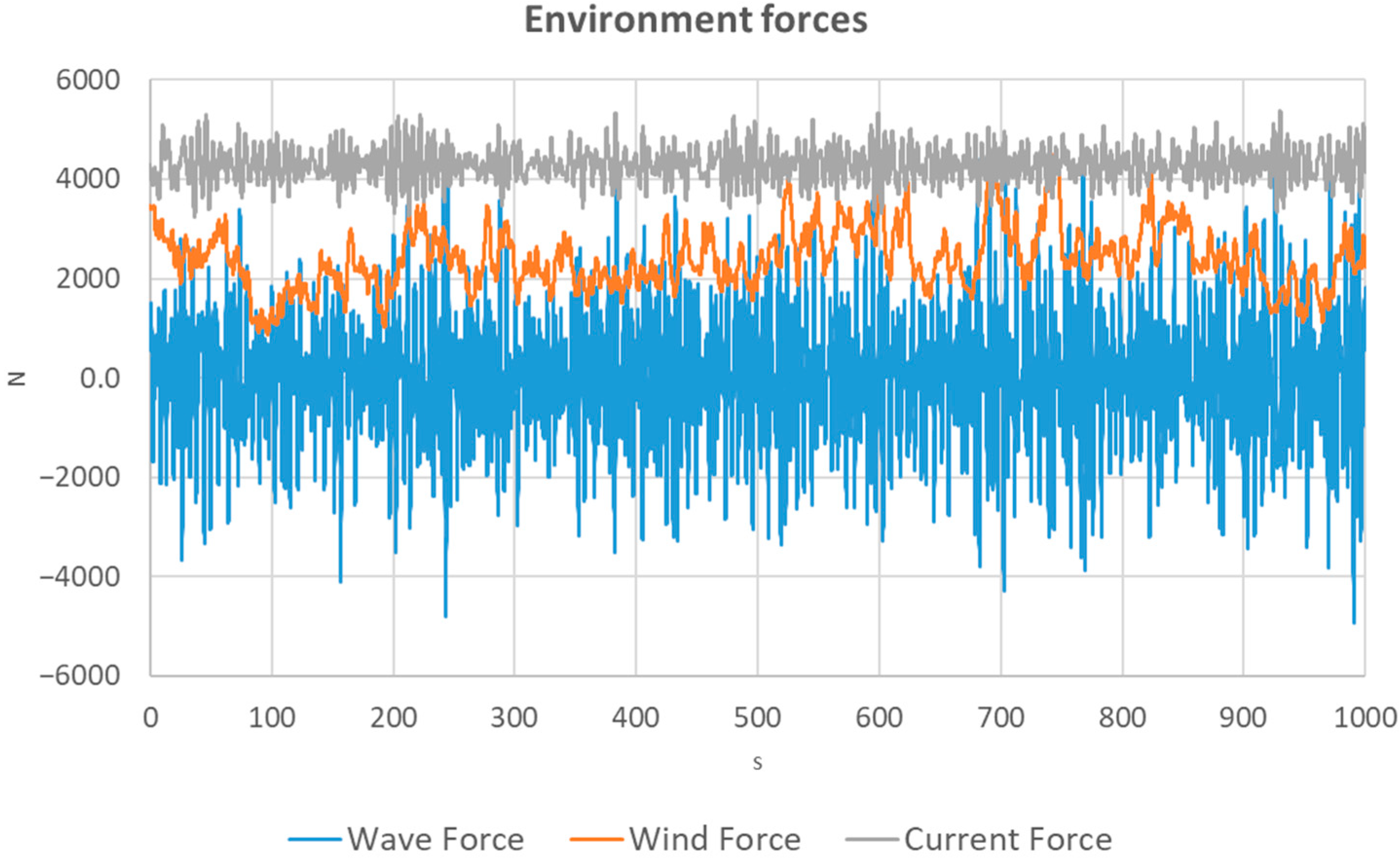
In another attempt, wind and current coefficients based on an empirical formula are added to the modules to check the effects from different environment loads.
Figure 26 shows the results from one of the modules. It seems that the wave loads (the blue curve) provide most of the dynamic part, while wind (the yellow line) and current (the gray line) loads are also in the same scale of magnitude.
Considering that this type of FPV is normally used in inland water, such as lakes or reservoirs, where waves are normally small, the design focus may drift to withstanding large winds. This aligns with the previous investigation on the feedback from some FPV manufacturers.
A more thorough analysis of the complete FPV system will be studied and summarized in follow-up papers.


