1. Introduction
In the discrete mathematical model of PWM rectifier, the model predictive control (MPC) predicts the grid side current, instantaneous power and other electrical quantities in the next control cycle; then the objective function is set according to the needs of the control system, an optimal voltage vector is obtained by solving the optimal objective function [
1,
2,
3,
4,
5,
6]. As a kind of predictive control, it has the advantages of not having a pulse width modulation module, flexible control scheme and high robust performance, and as such has aroused the interest of many scholars [
7,
8,
9,
10,
11,
12].
The finite control set model predictive direct power control (FCS-MPDPC) combines MPC with DPC [
13,
14,
15]. The objective function of FCS-MPDPC is composed of the error term between the instantaneous power and the given value, and an appropriate voltage vector is selected by solving the optimal objective function, which improves the control performance of the rectifier while maintaining a fast dynamic response. However, this method uses one voltage vector in a switching cycle. To achieve better control performance, the sampling frequency of the control system must be increased. Reference [
6] proposed a FCS-MPDPC, based on duty cycle optimization, which is also known as two-vector FCS-MPDPC. Different from the traditional FCS-MPDPC, the control method uses a zero vector and a non-zero vector in one cycle, and uses the zero-vector to regulate the instantaneous power smoothly. The two-vector FCS-MPDPC can maintain a fast dynamic response under the same sampling frequency, and at the same time reduce the current harmonic content and reduce the instantaneous power pulsation. Reference [
16] also proposes a two-vector FCS-MPDPC. The main difference between reference [
16] and reference [
6] is that reference [
6] takes the minimum sum of squares of instantaneous power error as the optimization objective, while reference [
16] takes the minimum instantaneous active power ripple as the control objective. These two strategies can achieve good control effect, but there is a certain coupling relationship in the control of instantaneous power. That is, when the instantaneous active power changes suddenly, it will affect the control of instantaneous reactive power, and even cause a fluctuation of instantaneous reactive power, and vice versa.
To solve this problem, a power decoupled FCS-MPDPC is proposed in reference [
17]. In this algorithm, weight coefficients are introduced into the instantaneous power error terms, and the weight coefficients will change with the changes in instantaneous power errors. The two-vector in references [
6], [
16] and [
17] are composed of the zero-vector. Based on the principle of volt second balance, the two-vector cannot synthesize the voltage vector of any angle in the plane, so they cannot fully meet the requirements of grid-connected control of PWM rectifier. Therefore, a new type of FCS-MPDPC is proposed in reference [
18], that is, a non-zero-vector can be combined not only with zero-vector, but also with adjacent non-zero vectors. There are 12 different vector combinations. Through the expansion of a vector combination, the algorithm can reduce the instantaneous power ripple and the harmonic content of current to a certain extent, but it cannot achieve a fixed switching frequency. In reference [
19], a three-vector FCS-MPDPC is proposed, which uses two non-zero vectors and one zero-vector. This algorithm has the advantages of high sinusoidal current, small instantaneous power ripple and the switching frequency is fixed. In reference [
20], a three-vector FCS-MPDPC is proposed to optimize the switching sequence. Different from reference [
19], the algorithm needs to predict the instantaneous power under 12 different vector combinations, and sets an objective function, based on the global power error, that is, to accumulate the sum of squares of the instantaneous power error terms in each switching action in a control cycle. Although the algorithm can further suppress the power ripple, reduce the total harmonic distortion (THD) and obtain a fixed switching frequency, it needs to predict the instantaneous power twelve times, which is complex and requires high processing speed of the control chip.
In addition, under three-phase unbalanced power grid condition, the negative sequence component will appear in the grid voltage. If the traditional FCS-MPDPC is still used, the THD of the grid side current will be larger and the instantaneous power ripple will be larger. Therefore, based on the new instantaneous power theory, a new three-vector FCS-MPDPC is proposed.
2. Mathematical Model of PWM Rectifier
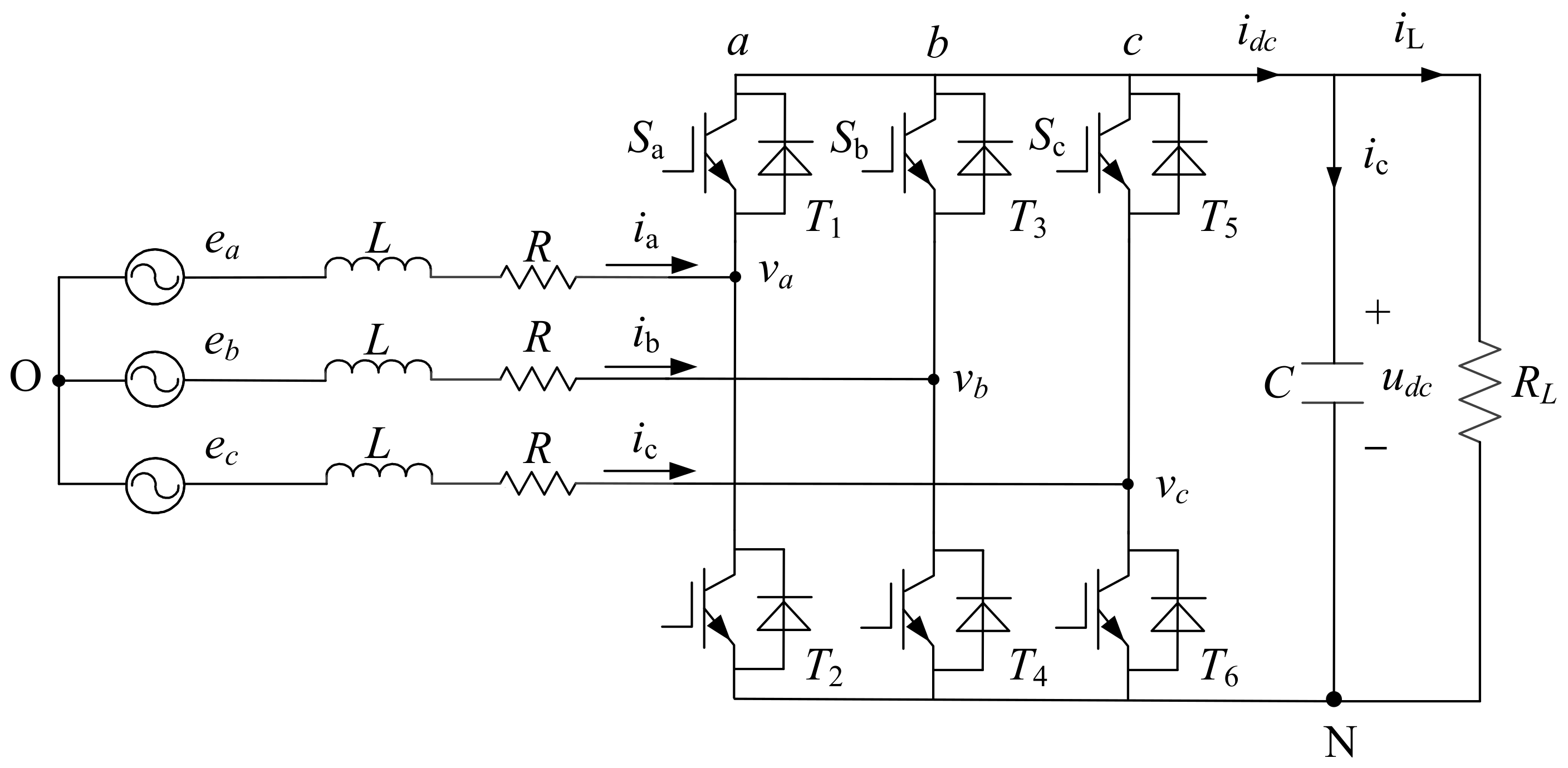
Figure 1 is the three-phase PWM rectifier. Among them,
ea,
eb and
ec are three-phase grid voltage,
ia,
ib and
ic are three-phase grid current,
va,
vb and
vc are three-phase bridge arm output voltage of PWM rectifier.
L is inductance.
R is parasitic resistance.
Based on Kirchhoff voltage law, the voltage loop equation of AC side of PWM rectifier is:
The corresponding vector equation is:
where,
E means the three-phase grid voltage vector.
I means the three-phase grid current vector.
V means the AC side output voltage vector of PWM rectifier.
Through abc/
αβ coordinate transformation, the PWM rectifier in the
αβ coordinate system is:
where,
eα and
eβ are components of
E,
iα and
iβ are components of
I, and
vα and
vβ are components of
V.
When the three-phase grid is unbalanced, the fundamental component is considered, in
dq coordinate system the
E is:
where,
and
are the fundamental voltage component of positive sequence and negative sequence.
Assuming that both
V and
I have positive and negative sequence components, we can get the following conclusion:
where,
and
are positive sequence and negative sequence fundamental voltage components, respectively,
and
are positive sequence and negative sequence fundamental current components, respectively.
2.1. Traditional Instantaneous Power in dq Coordinate System
Based on the instantaneous power theory [
21], the complex power
S is:
where, “*” denotes the conjugation of related variables. The instantaneous active and reactive power expressions is:
where,
p0 and
q0 are the DC components of instantaneous power,
pc2 and
qc2 are cosine components peak of the second order of instantaneous power,
ps2 and
qs2 are sine components peak of the second order of instantaneous power.
Further, the peak value of each component can be deduced as follows:
where,
and
are the projection of
on the dq axis respectively.
and
are respectively the projection of
on the dq axis.
and
are the projection of
on the dq axis.
and
are the projection of
on the dq axis.
Equation (8) shows I only contains four components () under unbalanced grid conditions, which cannot meet the control requirements of the six components of instantaneous power at the same time. If the control objective is to suppress the second harmonic component of p, the q will contain the second harmonic component, and the traditional FCS-MPDPC will not be applicable.
2.2. New Instantaneous Power in dq Coordinate System
To solve above problems, the new instantaneous power theory is used [
22]. In the new instantaneous power, the instantaneous active power is equivalent to the traditional instantaneous active power, but the new instantaneous reactive power is:
where,
is the vector with 90° lag
E, which is:
Thus, the
can be deduced as:
where,
By comparing Equation (8) with Equation (12), it can be seen that and . When the instantaneous active power output of PWM rectifier has no pulsation component, the instantaneous reactive power output also has no pulsation component, which can realize the new instantaneous power are constant under the condition of unbalanced power grid.
3. New FCS-MPDPC
The new instantaneous power in the
αβ coordinate system is:
where,
and
are the components of
.
According to Equation (13), the change rate of the new instantaneous power is:
Under unbalanced power grid condition, the differential form of
E is:
Substituting Equation (4) into Equation (15) obtains:
According to Equation (16), the rate of change of
α and
β components of
E in the static
αβ coordinate system is:
Similarly, the rate of change of
in the
αβ coordinate system is:
Combined with Equations (3), (14), (17) and (18), the differential expression of the new instantaneous power can be written as:
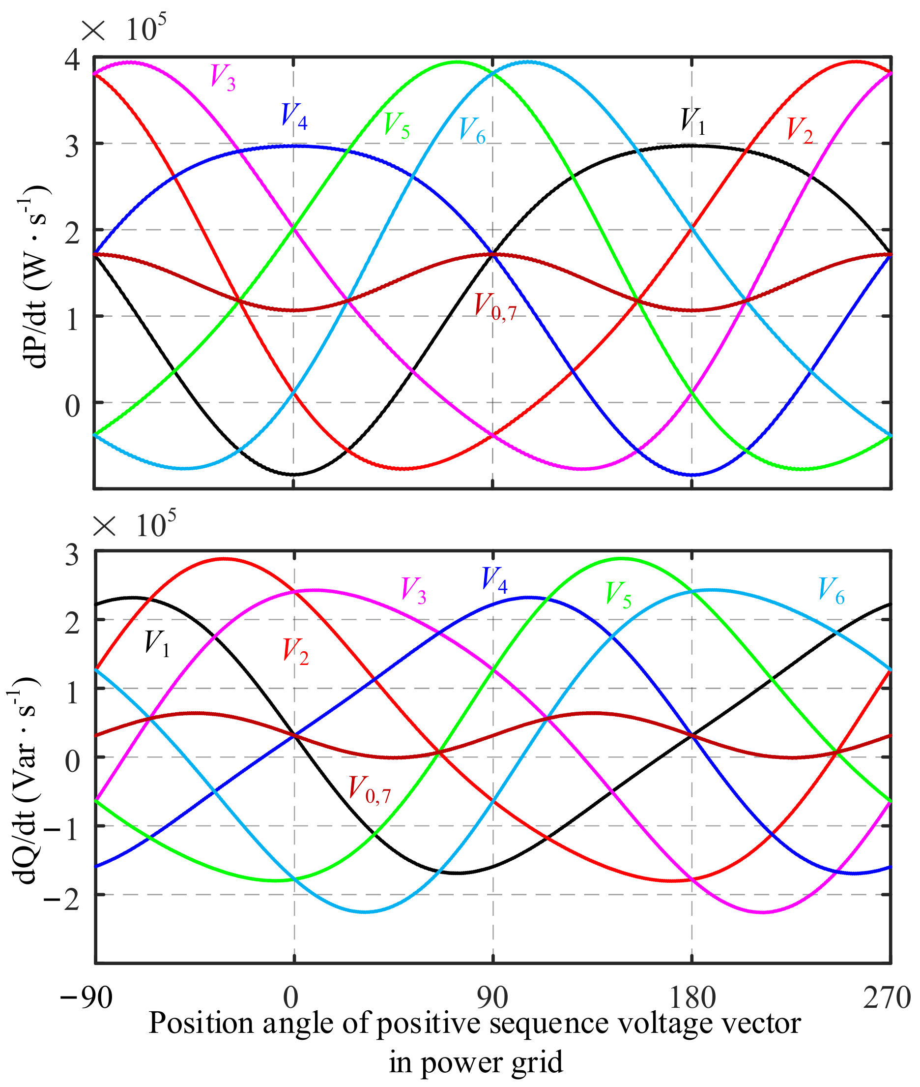
According to Equation (19), the change rate under the action of each voltage vector is calculated as follows:
Figure 2 shows the change of instantaneous power rate with the phase Angle of
E under the action of eight different voltage vectors (
V0–
V7). As can be seen from
Figure 2, in the case of grid unbalance, the instantaneous power change rate corresponding to the two zero voltage vectors is not constant, but a pulsating component.
To achieve the goal that the new instantaneous power output of the PWM rectifier follows the given value; the objective function is composed of the error term of this new instantaneous power and the given value. The objective function is:
In the Equation (21), pk+1 and are the predicted values of p and in the next control period, respectively. pref and are given values, respectively.
A three-vector FCS-MPDPC is proposed, in a control cycle one zero vector and two adjacent non-zero voltage vectors are selected. There are six different combination modes of two non-zero vectors, namely {V1, V2}, {V2, V3},…, {V6, V1}. Based on the three voltage vectors, the control system needs to select the most suitable group from these six combinations, and generate six PWM control signals, according to the action time and action sequence of each vector.
The selection and the calculation of action time of the vector occur at the same time. Before the most suitable vector combination is obtained, the action time of each vector needs to be calculated, and then the instantaneous power of the next control cycle corresponding to the vector combination is predicted. Finally, the most suitable voltage vector combination is selected by the smallest objective function.
Assuming that the optimal non-zero vector combination in a current control cycle is {
V1,
V2}.
V0 is the zero vector, the vector combination used by the control system is {
V1,
V2,
V0}. The change rates of instantaneous active power corresponding to the voltage vector combination {
V1,
V2,
V0} are
sp1,
sp2, and
sp0, respectively, and the corresponding instantaneous reactive power change rates are
sq1,
sq2,
sq0, then the instantaneous rate in the next control cycle. The predicted value of power is as follows:
where,
Ts means the control period.
t1 and
t2 are the action time of
V1 and
V2, respectively.
Since the control goal of model prediction is to minimize
cf, the minimum
cf in Equation (21) is used as the constraint condition, the time of each non-zero vector should satisfy:
By solving the Equation (23), the action time of
V1 and
V2 was found to be:
After obtaining the action time
t1 and
t2, when
t1 or
t2 is less than zero, then
t1 or
t2 is equal to zero; when
t1 or
t2 is greater than
Ts, then
t1 or
t2 is equal to
Ts. After simply processing
t1 and
t2 of the non-zero voltage vector, when
t1 +
t2 >
Ts, the action time
t0,
t1 and
t2 should be adjusted to:
Substituting Equation (25) into Equation (22), the predicted value of instantaneous power under the action of the voltage vector combination {V1, V2, V0} can be calculated. Then combine Equation (21) to get the corresponding objective function value cf1. In the same way, the values cf2, cf3,…, cf6 of the objective function under the action of other vector combinations can be calculated. To minimize the instantaneous power error, the voltage vector combination corresponding to the minimum cf is the optimal voltage vector combination. When the optimal voltage vector combination is determined, it can be modulated according to the SVPWM method.
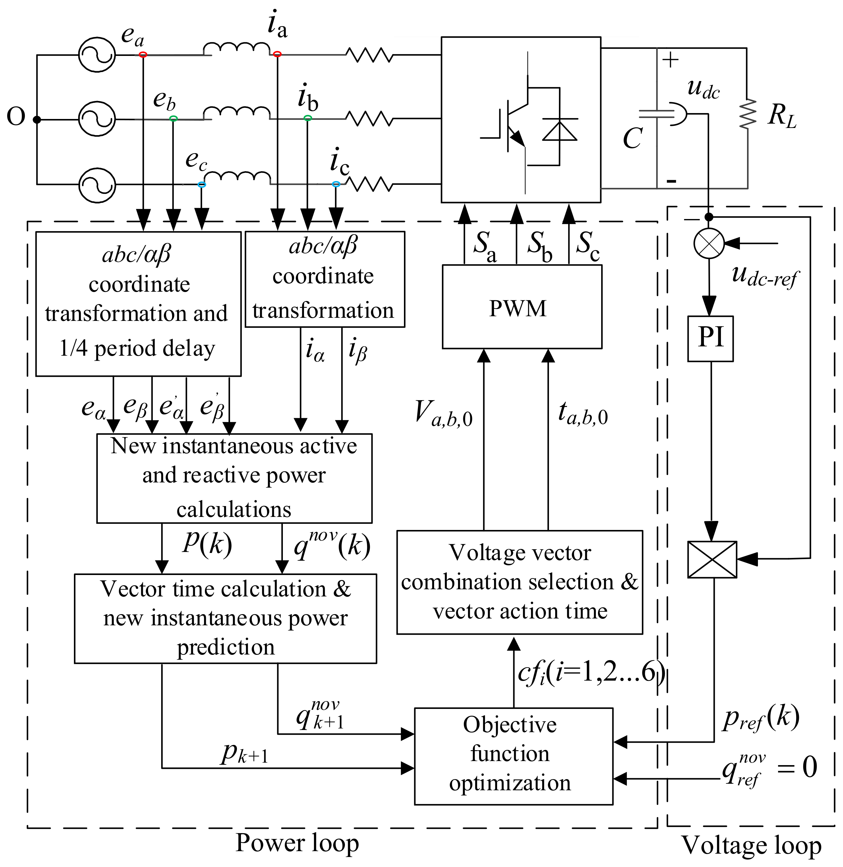
Figure 3 is the new FCS-MPDPC control diagram, which is mainly divided into six key links, such as delay vector solution, new instantaneous power calculation, new instantaneous power prediction, objective function optimization, voltage vector selection and operation time calculation and pulse width modulation.
4. Simulation and Experimental
To verify the effectiveness of the new FCS-MPDPC, and an experimental platform is built. In addition, this paper also compares and analyzes the three-vector FCS-MPDPC in the reference [
19]. The sampling frequency of the two methods is 10 kHz.
Table 1 indicates the parameters of the control system. In order to create the unbalanced situation of three-phase power grid, 3 Ω unbalanced resistors are connected in series in the A-phase loop of PWM rectifier.
4.1. The Simulation
In the Matlab 2021a of MathWorks, the traditional and new FCS-MPDPC simulation models are built, and the simulation results are analyzed.
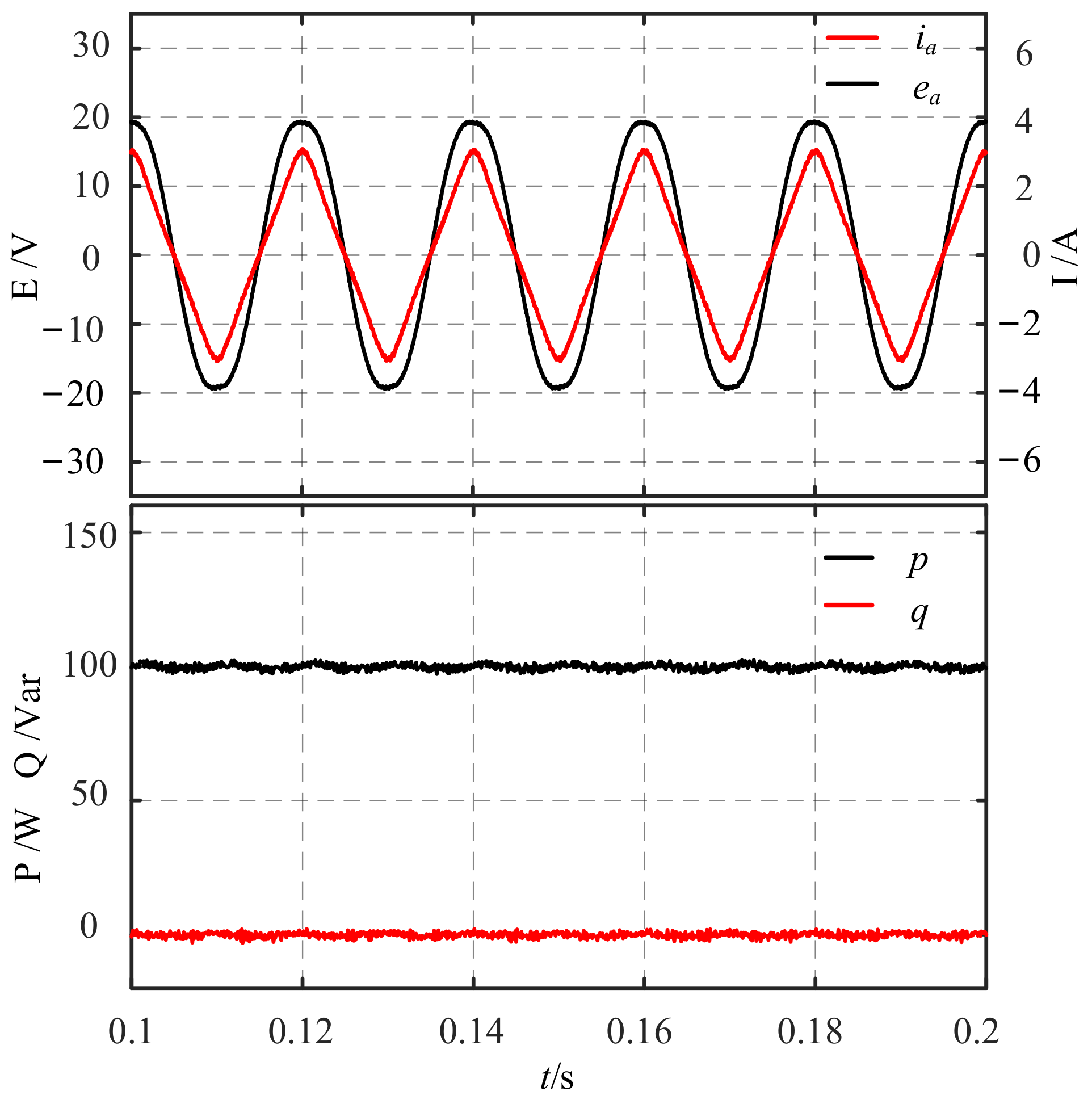
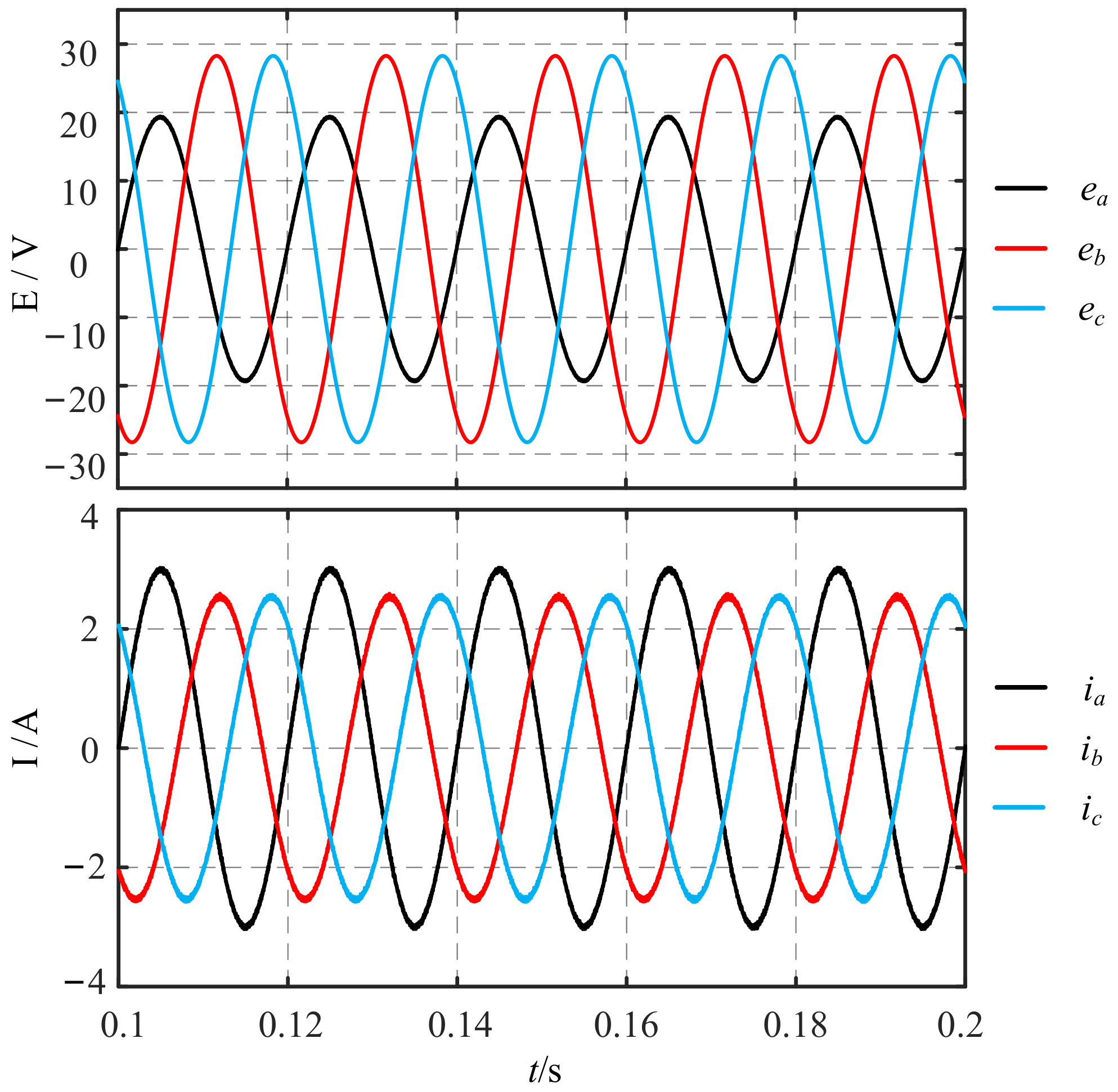
Under unbalanced power grid conditions, the sinusoidal degree of three-phase current waveforms in the traditional FCS-MPDPC is low, as shown in
Figure 4 and
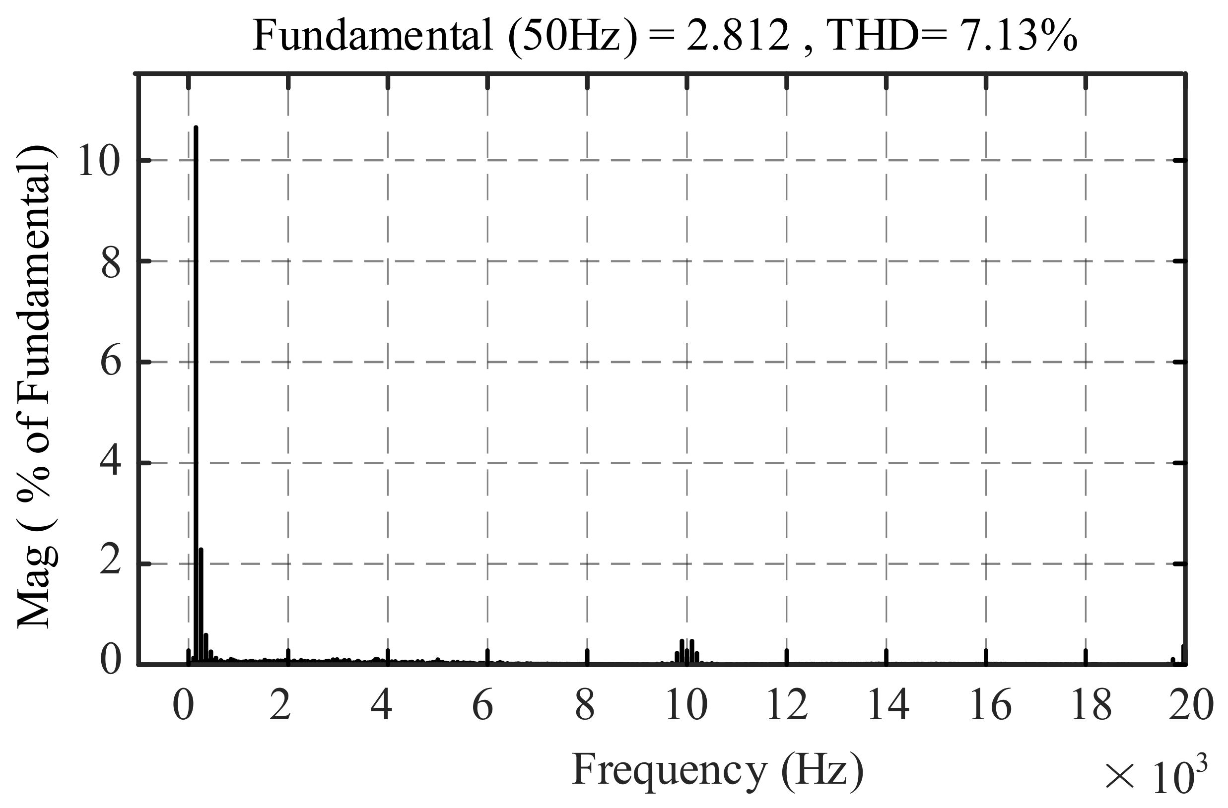
Figure 5, especially where the A-phase current waveform is seriously distorted, the three-phase current is asymmetric, and the instantaneous power has pulsating components. According to the spectrum analysis of A-phase current, in
Figure 6, the THD of A-phase current is 7.13%, which cannot be obtained to meet the requirements of PWM rectifier grid-connected control; the amplitude of fundamental current is 2.812 A. In addition, there are many low-order harmonics, especially the third and fifth harmonics. Therefore, under unbalanced three-phase power grid condition, if the traditional FCS-MPDPC is adopted, the harmonic content of three-phase power grid current is high, which will cause certain “pollution” to the power grid.
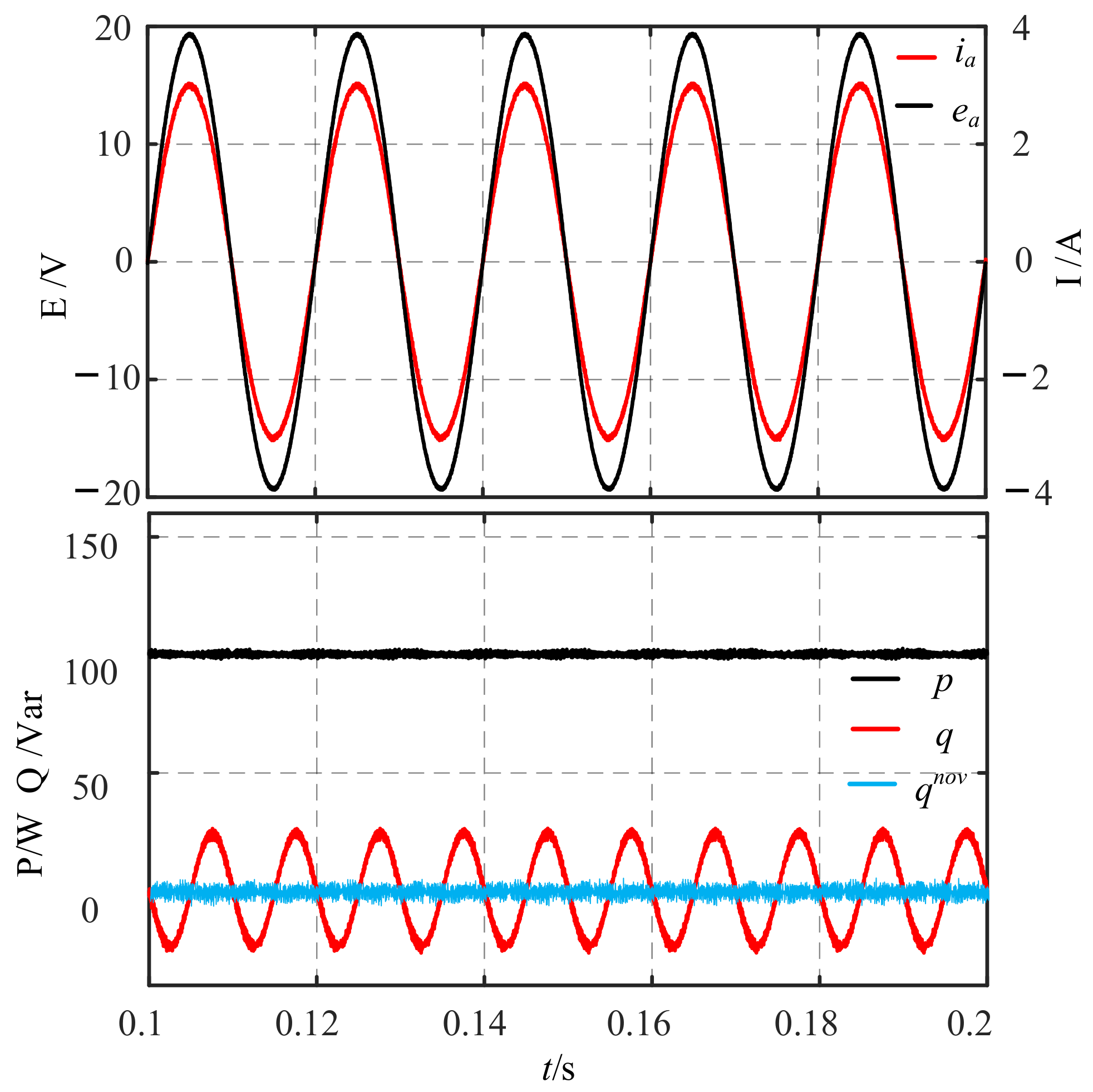
It can be seen from Equations (7) and (11), if the second harmonic of DC side voltage is to be suppressed, and must be suppressed, but and cannot be eliminated, that is, the instantaneous reactive power is not a constant value, but a sinusoidal pulsating component. The unbalanced control method for suppressing the second harmonic component, only the control signal of instantaneous active power can be a fixed value or step command, and the instantaneous reactive power can only be sinusoidal pulsating component.
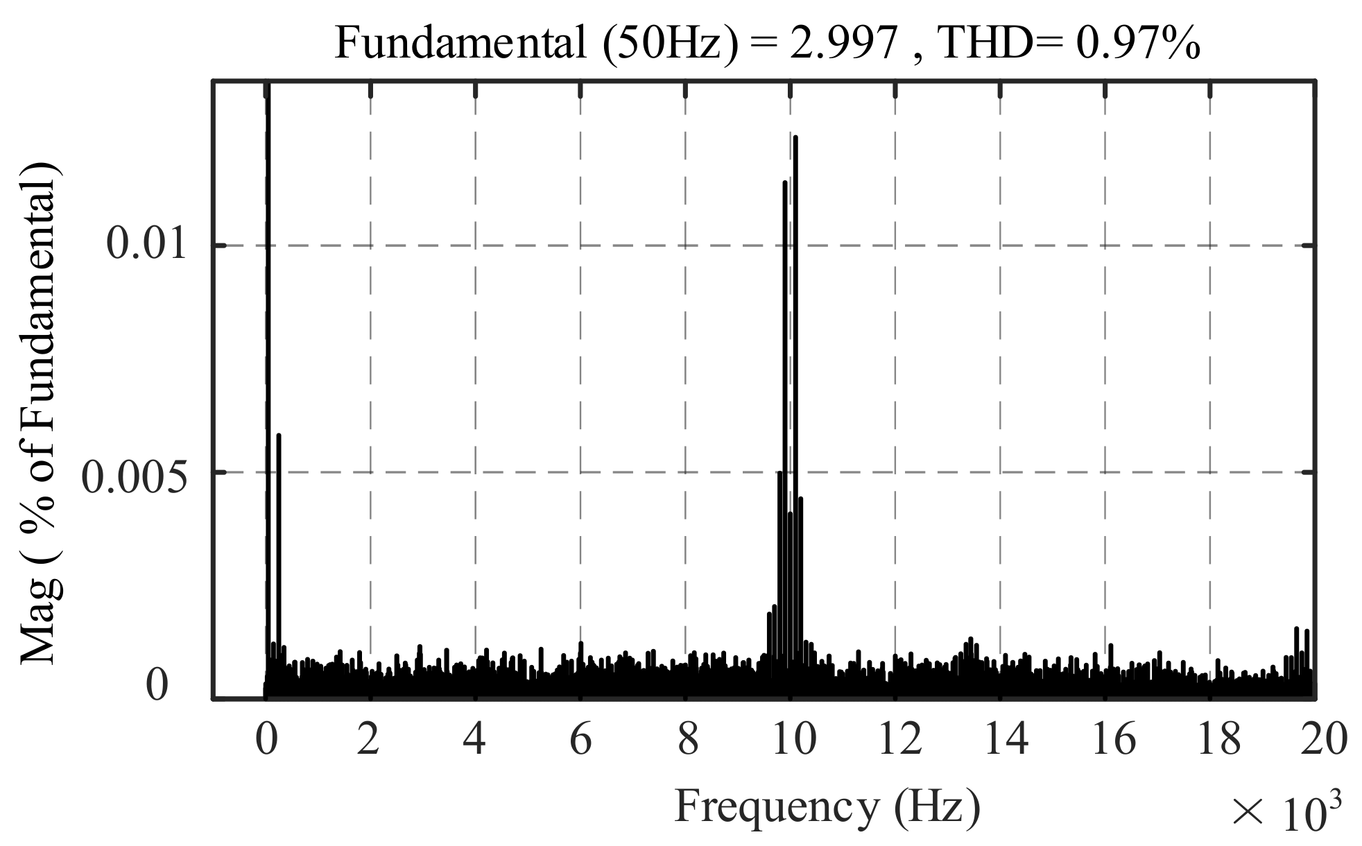
On the contrary, the new FCS-MPDPC has good steady-state performance. In
Figure 7 and
Figure 8, the current waveform of three-phase power grid is highly sinusoidal, voltage and current are in the same phase, and the new type of instantaneous power pulsation is small. By analyzing the spectrum of A-phase current, shown in
Figure 9, the amplitude of fundamental current is 2.997 A; the THD of current is only 0.97%, which significantly reduces the low-order harmonic component of current, and the high-order harmonic is mainly concentrated in the integral multiple of switching frequency. The filter inductor is simple in design.
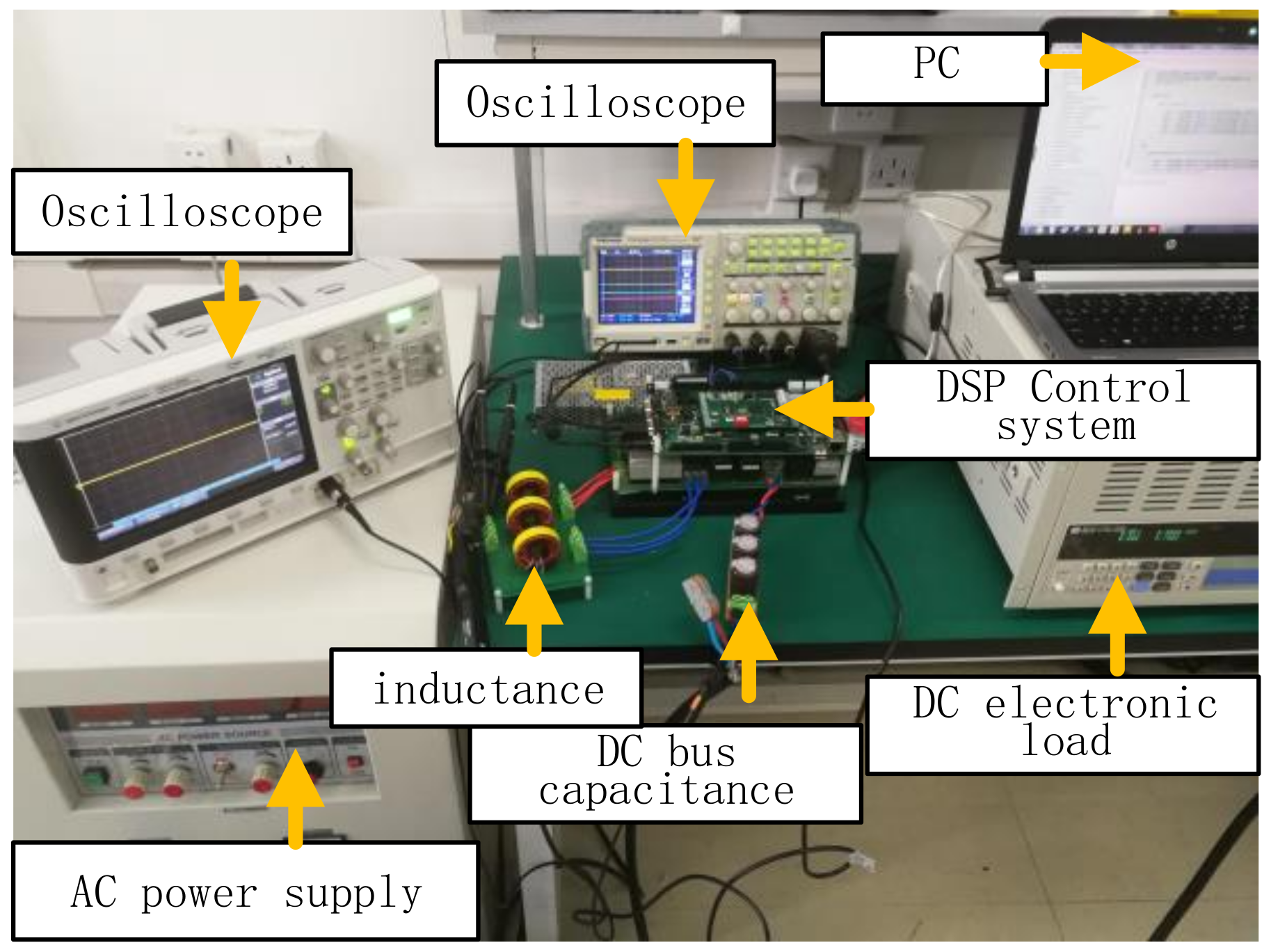
4.2. The Experiment
The experiments were carried out on the experimental platform, as shown in
Figure 10.
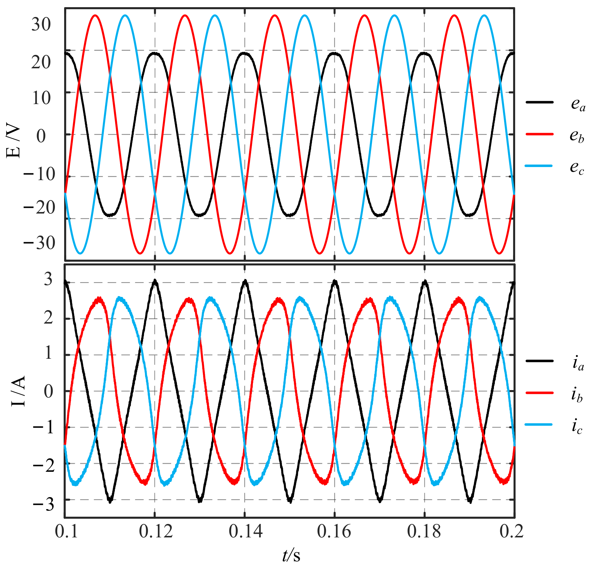
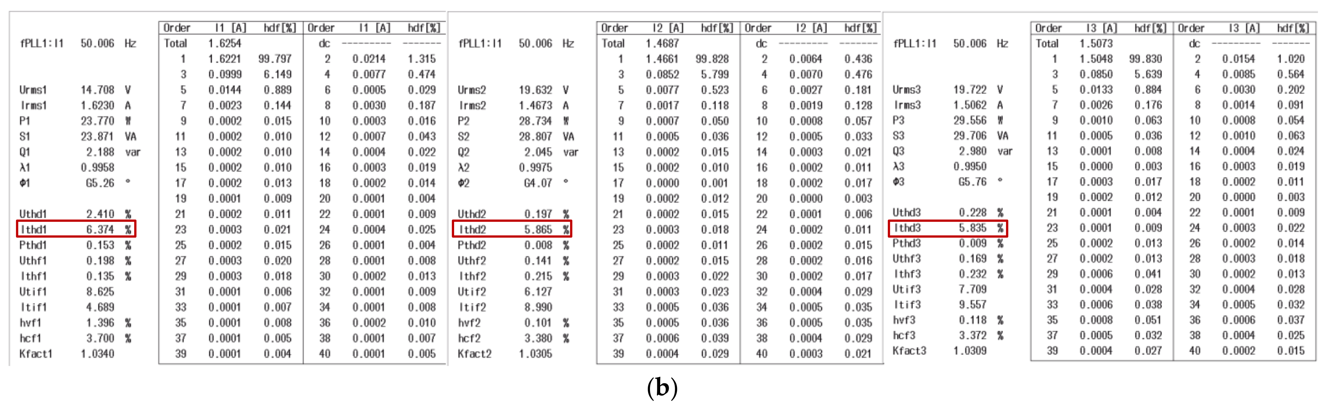
Figure 11 and
Figure 12, respectively, show the experimental results of traditional and new FCS-MPDPC under power grid unbalance condition. In
Figure 11, waveforms of the three-phase current in the traditional FCS-MPDPC is seriously distorted; especially the A-phase current waveform is approximately triangular. Further spectrum analysis of the three-phase current shows that THD of the three-phase current is 6.374%, 5.865% and 5.835%, respectively, which cannot meet the requirements of current THD of PWM rectifier grid-connected control [
23].
Under the unbalanced three-phase power grid condition, if the traditional FCS-MPDPC is adopted, the harmonic content of three-phase current will be too much, especially the third and fifth harmonics, which will cause certain interference to the power grid.
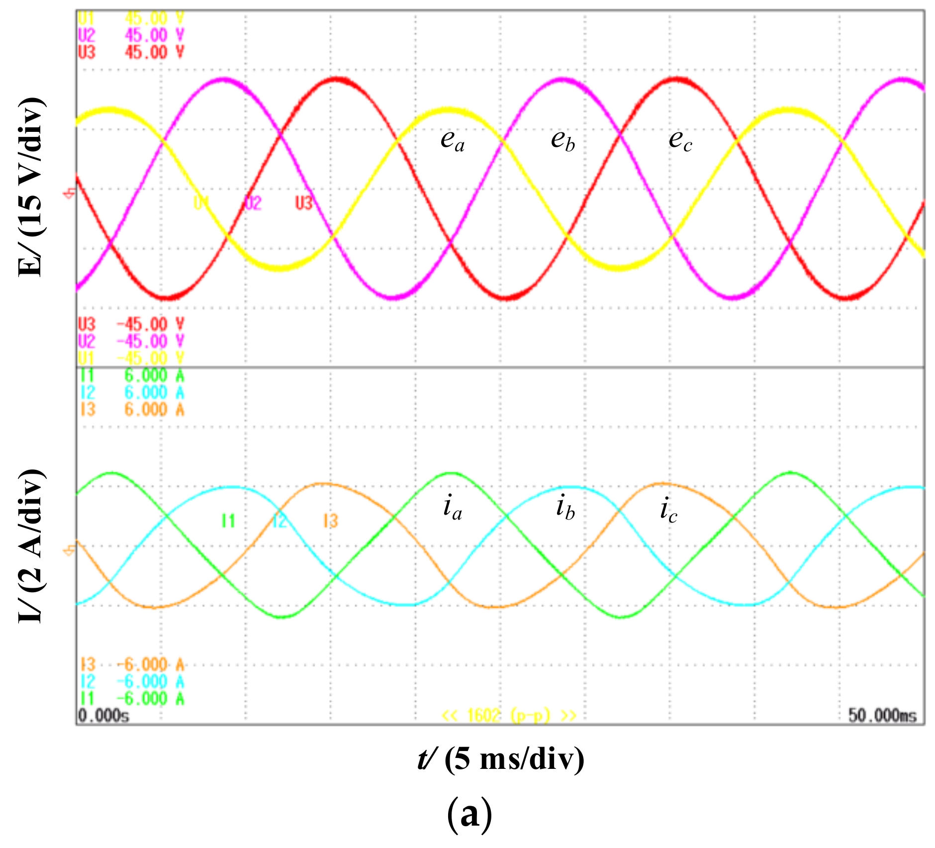
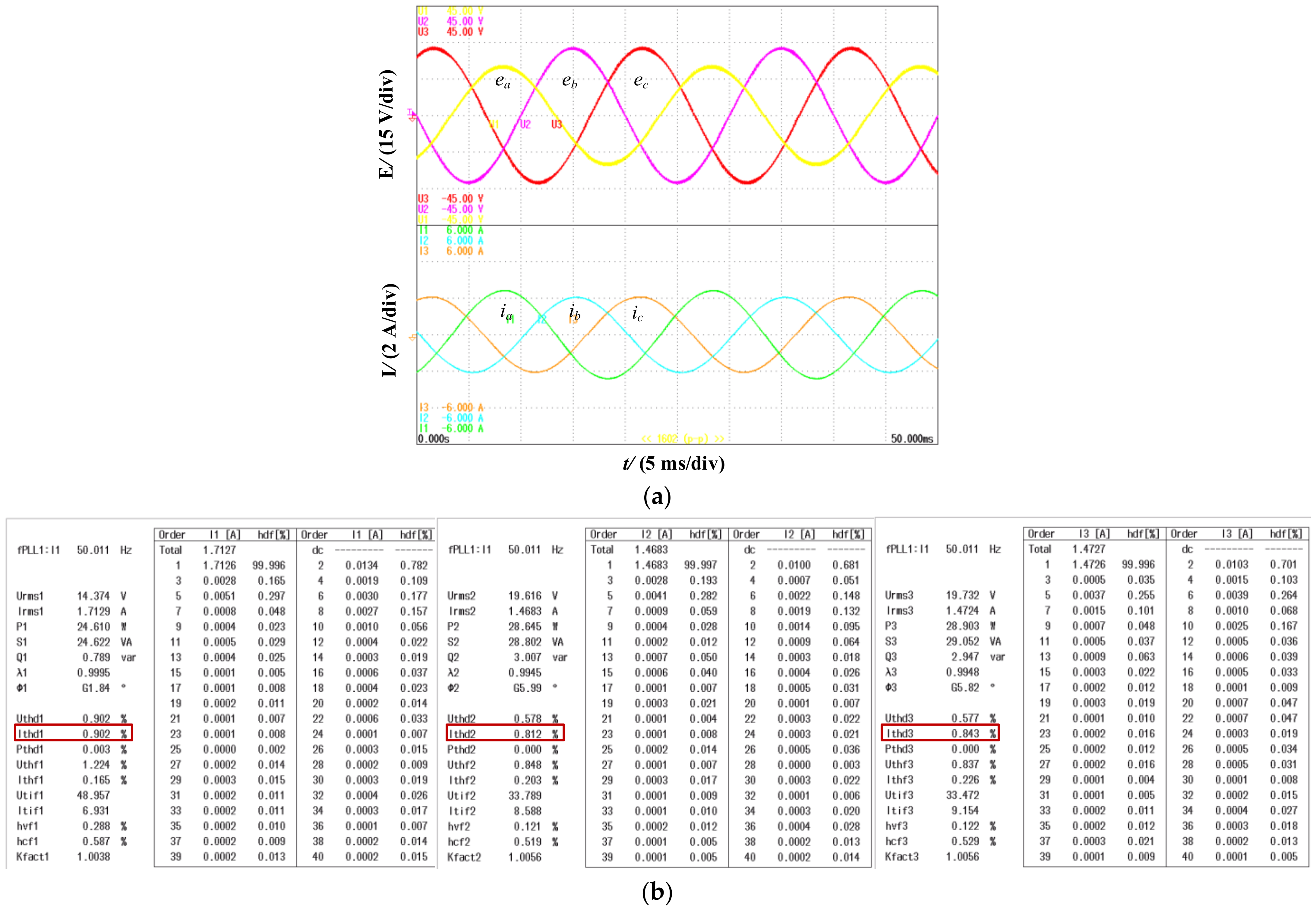
On the contrary, the new FCS-MPDPC has good steady-state performance. In
Figure 12, current waveforms of the three-phase grid has high sinusoidal degree and fewer burrs. Voltage and current are in the same phase. From spectrum analysis of three-phase current, the THD of three-phase current is 0.902%, 0.812% and 0.843%, respectively, which is about 1/7 of the three-phase current THD in traditional FCS-MPDPC. Therefore, compared with the traditional FCS-MPDPC, under grid unbalance conditions, the new FCS-MPDPC can suppress the harmonic component of the current on the grid side and improve the performance of the control system.
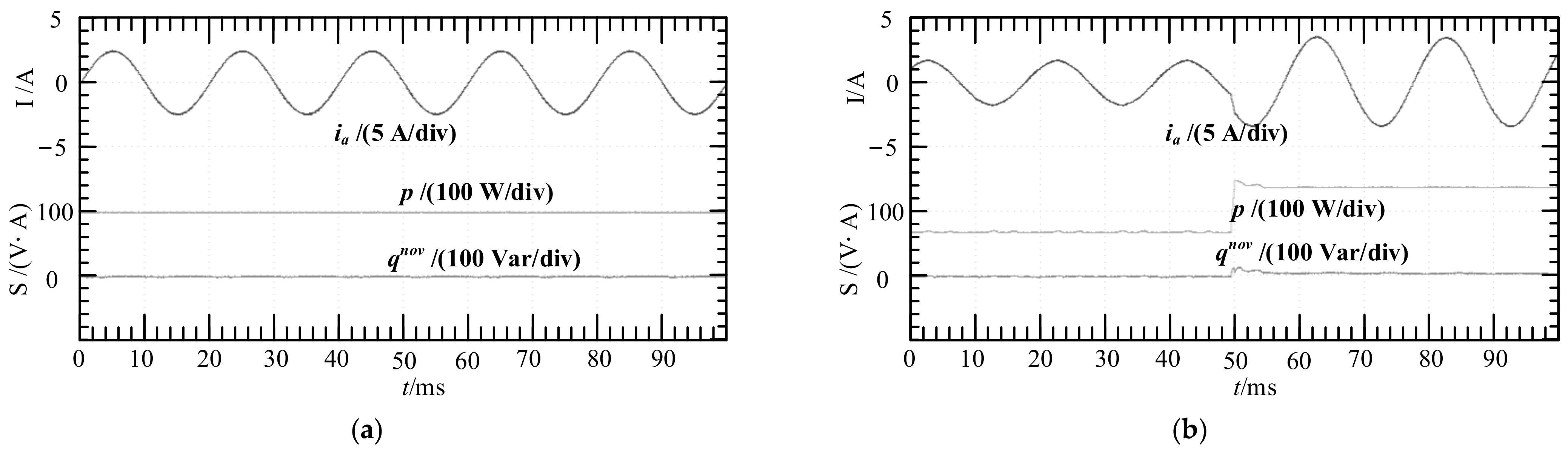
In addition, this paper also verifies the effectiveness of the new FCS-MPDPC under three-phase power grid balance.
Figure 13 shows the experimental results.
Figure 13a shows that the new FCS-MPDPC can suppress the harmonic component of the current and reduce the instantaneous active and reactive power pulsation. In
Figure 13b, when the new instantaneous active power changes from 70 W to 140 W, FCS-MPDPC can quickly track the change of the given value while keeping the new instantaneous reactive power. The harmonic analysis of current shows that the THD is small. The low order harmonic content is less, and the high order harmonic is mainly concentrated on the integral multiple of the switching frequency, which is conducive to the filtering of high order harmonic components. It has good dynamic response performance.


