


Tests of Fire Circuit Breakers (FCBs) to Assess Their Suitability for Use in Construction Objects


Abstract
:1. Introduction
- fire pumps,
- fire alarm systems—optical and voice alarm devices,
- voice alarm systems,
- smoke and heat control systems—including powering ventilators and smoke damper drives),
- emergency and evacuation lighting,
- elevators intended for rescue teams.
2. Legal Requirements—Analysis and Evaluation of the Current State
- in buildings where there is a fire zone of more than 1000 m3 or a potentially explosive atmosphere,
- at the metro station control room,
- in tunnels (separately in each nave),
- in garrison school shooting ranges and special ranges.
- an activating device,
- a signalling device,
- an executive device.
3. Materials and Methods
3.1. Research Methods for Assessing the Suitability of FCBs
- functional tests,
- environmental tests,
- EMC electromagnetic compatibility tests.
3.1.1. Functional Tests—Materials and Methods
- when the fragile element is broken for type A switches,
- after the fragile element is broken and the switch is pressed for type B switches.
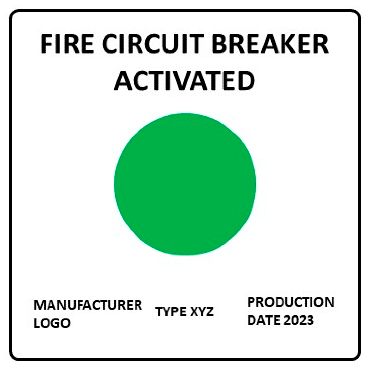
- housing and faceplate colour is red according to RAL 3000;
- the visible area of the control panel is white colour according to RAL 9010;
- the description colour is black according to RAL 9005;
- the operating button colour is yellow according to RAL 1018.
3.1.2. Environmental Tests—Materials and Methods
3.1.3. Electromagnetic Compatibility Tests—Materials and Methods
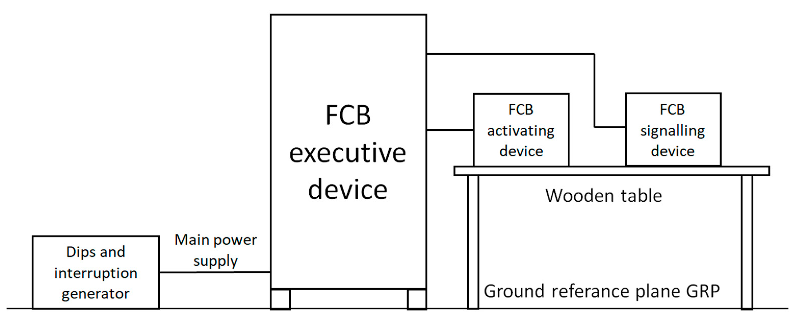
- Changes in the mains voltage (only for the executive device): This is intended to demonstrate the ability of the device to operate correctly despite changes in the mains conditions in the range of Unom +10–15% (Unom—nominal voltage), test method and test equipment according to IEC 61000-4-11:2004/AMD1:2017 [33], test setup as shown in Figure 11 (EM test manufacturer)
- Mains voltage decays and short interruptions (only for the executive device): This is intended to demonstrate the resistance of the device to short AC mains voltage decays (drops) and interruptions, such as those caused by load switching and the operation of protective devices in distribution networks; the test includes applying short-circuit decays and interruptions of the mains voltage to the device (3 voltage drops of 20%, 30%, 60% and 100% each), test method and test equipment according to IEC 61000-4-11:2004/AMD1:2017, test setup as shown in Figure 11 (EM test manufacturer)
- Electrostatic discharge: This is intended to demonstrate the immunity of the equipment to electrostatic discharges caused by operators of the equipment, who may be electrostatically charged, touching this equipment or other equipment in the vicinity; the test includes applying electrostatic discharges to parts of the equipment accessible to the operator and to coupled planes located at a distance of 0.1 m from the equipment (10 discharges each of 2, 4 and 8 kV for air discharges and 6 kV for contact discharge), test method and test equipment according to IEC 61000-4-2:2008 [34], test setup as shown in Figure 12 (EM test manufacturer)
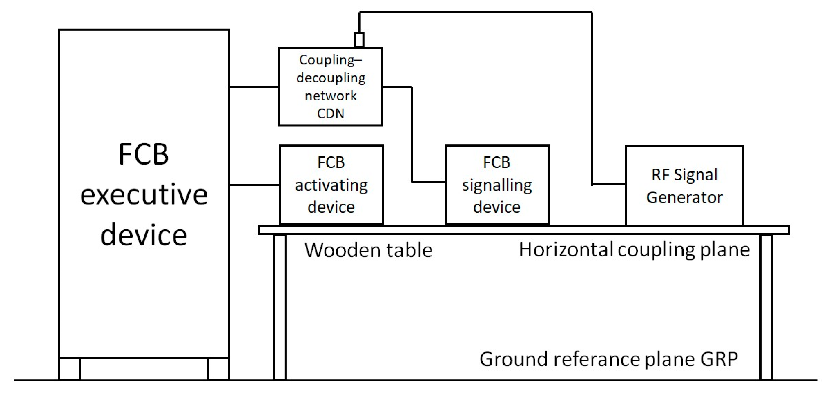
- Radiated electromagnetic field: This is intended to demonstrate the immunity of a device to electromagnetic fields generated, for example, by portable radio transceivers or mobile phones; the test consists of exposing the device to an electromagnetic field with a field strength of 10 V/m, frequency sweeping from 80 MHz to 2.7 GHz, with the signal modulated both in amplitude (first test) and pulse (second test), test method and test equipment according to IEC 61000-4-3:2020 [35], test setup as shown in Figure 13 (EMCO and Schwarzbeck—Mess-Elektronik manufacturers)
- Conducted disturbances induced by electromagnetic fields: This is intended to demonstrate the immunity of a device to conducted disturbances induced by electromagnetic fields in the wiring field (e.g., generated by portable radio transceivers, radiotelephones); the test includes introducing a radio frequency disturbance with a voltage level of 10 V, in the range of 150 kHz to 100 MHz, to various inputs or outputs of the device under test, with a signal modulated both in amplitude (first test) and in pulse (second test), test method and test equipment according to IEC 61000-4-6:2013 [36], test setup as shown in Figure 14 (EM test manufacturer)
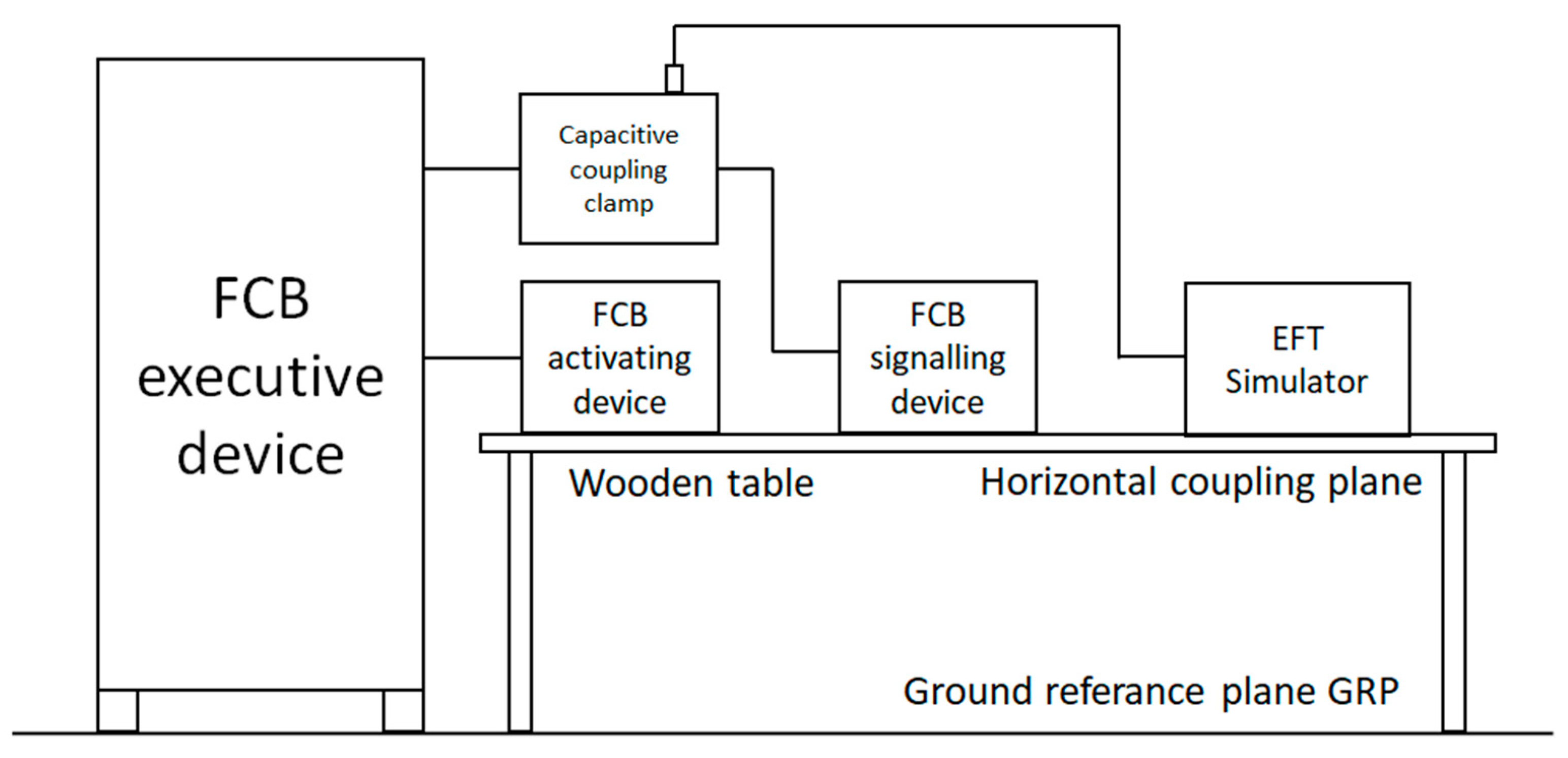
- Series of fast electrical transients: This is intended to demonstrate the immunity of the device to a series of fast transients of low energy, which can be caused by relays, contacts, as well as switching loads of an inductive nature that can be induced in the signal circuits; the test consists in introducing a series of fast transients to the power supply lines and signal inputs/outputs of the device with a voltage value of 2 kV for the AC power supply lines and 1 kV for the other lines at a repetition rate of 100 kHz, for 1 min, test method and test equipment according to IEC 61000-4-4:2012 [37], test setup as shown in Figure 15 (EM test manufacturer)
- Slow high-energy voltage surges: This is intended to demonstrate the immunity of the equipment to relatively slow, transient high-energy pulses that may be induced in power and signal cables from close lightning discharges or from switching in the power system or in the low-voltage network; the test involves the introduction of slow, transient high-energy pulses in both line-to-line and line-to-ground coupling systems at 0.5 and 1 kV (line-to-line) and 0.5; 1 and 2 kV (line-to-ground) for AC power lines and 0.5 and 1 kV (line-to-ground) for other lines, test method and test equipment according to IEC 61000-4-5:2014/AMD1:2017 [38], test setup as shown in Figure 16 (EM test manufacturer)
4. Results
- the FCB activating devices: 36 pieces received positive results in environmental class 2 (23 pieces of type A and 13 pieces of type B),
- the FCB signalling devices: 1 piece received positive results in environmental class 1 and 3 pieces in environmental class 2.
- the FCB executive devices: 4 pieces received positive results in environmental class 1 and 2 pieces in environmental class 2.
5. Discussion and Conclusions
Author Contributions
Funding
Data Availability Statement
Conflicts of Interest
References
- Regulation of the Minister of Internal Affairs of 3 November 1992 on Fire Protection of Buildings, Other Facilities and Areas (Polish Journal of Laws: Dz. U. Nr 92, poz. 460, as Amended), Outdated Document. Available online: https://isap.sejm.gov.pl/isap.nsf/DocDetails.xsp?id=WDU19920920460 (accessed on 20 April 2024).
- Regulation of the Minister of Infrastructure and Construction of 17 November 2016 on the Method of Declaring the Performance of Construction Products and the Method of Marking Them with the Construction Mark (Polish Journal of Laws: Dz. U. poz. 1966, as Amended). Available online: https://isap.sejm.gov.pl/isap.Nsf/DocDetails.xsp?id=WDU20160001966 (accessed on 20 April 2024).
- Regulation of the Minister of Internal Affairs and Administration of 17 September 2021 on Reconciliation of the Land or Plot Development Project, Architectural and Construction Project, Technical Project and the Project of Fire-Fighting Equipment in Terms of Compliance with the Fire Protection Requirements (Polish Journal of Laws: Dz. U. poz. 1722). Available online: https://isap.sejm.gov.pl/isap.nsf/DocDetails.xsp?id=WDU20210001722 (accessed on 20 April 2024).
- National Fire Protection Association. NFPA 72 National Fire Alarm and Signaling Code, 2022 ed.; National Fire Protection Association: Quincy, MA, USA, 2022. [Google Scholar]
- IEC 60364-5-56:2018; Low-Voltage Electrical Installations—Part 5–56: Selection and Erection of Electrical Equipment–Safety Services. International Electrotechnical Commission: Geneva, Switzerland, 2014.
- Lee, D.A.; Trotta, A.M.; King, W.H., Jr. New Technology for Preventing Residential Electrical Fires: Arc-Fault Circuit Interrupters (AFCIs). Fire Technol. 2000, 36, 145–162. [Google Scholar] [CrossRef]
- Franklin, F.F. Circuit Breakers: The Myth of Safety. Prof. Saf. Des. Plaines 1990, 6, 28. [Google Scholar]
- Aronstein, J. Faulty Residential Circuit Breakers–A Persistent Fire Safety Problem in IEEE. Open J. Ind. Appl. 2023, 4, 75–86. [Google Scholar] [CrossRef]
- Wang, L.; Li, D.; Guo, C. Technical Appraisal Method of Circuit Breaker Material Evidence in Fire Journal of Physics: Conference Series. In Proceedings of the 10th Annual International Conference on Material Science and Environmental Engineering, Nanjing, China, 25–27 November 2022. [Google Scholar]
- Wiatr, J.; Orzechowski, M. Uproszczony projekt zasilania hali produkcyjnej z przeciwpożarowym wyłącznikiem prądu zgodnie z wymaganiami normy PN-HD 60364-5-56:2019-01. Elektro Info 2021, 6, 7–8. [Google Scholar]
- He, J.; Bao, G. Design of Safety Fire Switch for Photovoltaic Module. Low Volt. Appar. 2023, 7, 42–47. [Google Scholar]
- Regulation of the Minister of Infrastructure of 12 April 2002 on the Technical Conditions to be Met by Buildings and Their Location (Polish Journal of Laws: Dz. U. z 2022 r. poz. 1225). Available online: https://isap.sejm.gov.pl/isap.nsf/DocDetails.xsp?id=WDU20220001225 (accessed on 20 April 2024).
- Regulation of the Minister of Defense of 4 October 2001 on the Technical Conditions to be Met by Garrison Shooting Ranges and Their Location (Polish Journal of Laws: Dz. U. Nr 132, poz. 1479, as Amended). Available online: https://isap.sejm.gov.pl/isap.nsf/DocDetails.xsp?id=WDU20011321479 (accessed on 20 April 2024).
- Regulation of the Minister for Infrastructure of 17 June 2011 on the Technical Conditions to be Met by Metro Structures and Their Location (Polish Journal of Laws: Dz. U. Nr 144, poz. 859). Available online: https://isap.sejm.gov.pl/isap.nsf/DocDetails.xsp?id=WDU20111440859 (accessed on 20 April 2024).
- Regulation of the Minister of Infrastructure of 24 June 2022 on Technical and Construction Regulations for Public Roads (Polish Journal of Laws: Dz. U. poz. 1518). Available online: https://isap.sejm.gov.pl/isap.nsf/DocDetails.xsp?id=WDU20220001518 (accessed on 20 April 2024).
- PN-N-01256-4:1997; Safety Signs–Technical Fire Protection Measures. The Polish Committee for Standardization PKN: Warsaw, Poland, 1997.
- SEP-E-005:2013; Selection of Electrical Conductors to Supply Power to Fire-Fighting Equipment Whose Operation Is Essential During a Fire. Association of Polish Electrical Engineers SEP: Warsaw, Poland, 2013.
- IEC 60947-2:2016; Low-Voltage Switchgear and Control Gear–Circuit-Breakers. International Electrotechnical Commission: Geneva, Switzerland, 2016.
- IEC 60947-3:2020; Low-Voltage Switchgear and Control Gear–Switches, Disconnectors, Switch-Disconnectors and Fuse-Combination Units. International Electrotechnical Commission: Geneva, Switzerland, 2020.
- Act of 16 April 2004 on Construction Products (Polish Journal of Laws: Dz. U. z 2021 r. poz. 1213). Available online: https://isap.sejm.gov.pl/isap.nsf/DocDetails.xsp?id=WDU20210001213 (accessed on 20 April 2024).
- Regulation of the Minister of Infrastructure and Construction of 17 November 2016 on National Technical Assessments (Polish Journal of Laws: Dz. U. poz. 1968). Available online: https://isap.sejm.gov.pl/isap.nsf/DocDetails.xsp?id=WDU20160001968 (accessed on 20 April 2024).
- EN 54-11:2001/A1:2005; Fire Detection and Fire Alarm Systems–Manual Call Points. European Standards. The European Committee for Standardization CEN: Brussels, Belgium, 2005.
- IEC 60068; Environmental Tests (Series of Standards). International Electrotechnical Commission: Geneva, Switzerland, 2024.
- IEC 60068-2-1:2007; Environmental Testing—Part 2–1: Tests–Test A: Cold. International Electrotechnical Commission: Geneva, Switzerland, 2007.
- IEC 60068-2-78:2012; Environmental Testing—Part 2–78: Tests–Test Cab: Damp Heat, Steady State. International Electrotechnical Commission: Geneva, Switzerland, 2012.
- IEC 60529:1989; Degrees of Protection Provided by Enclosures (IP Code). International Electrotechnical Commission: Geneva, Switzerland, 1989.
- IEC 60068-2-6:2007; Environmental Testing—Part 2–6: Tests–Test Fc: Vibration (Sinusoidal). International Electrotechnical Commission: Geneva, Switzerland, 2007.
- IEC 60068-2-75:2014; Environmental Testing—Part 2-75: Tests–Test Eh: Hammer Tests. International Electrotechnical Commission: Geneva, Switzerland, 2014.
- IEC 60068-2-27:2008; Environmental Testing—Part 2–27: Tests–Test Ea and Guidance: Shock. International Electrotechnical Commission: Geneva, Switzerland, 2014.
- ISO 22479:2019; Corrosion of Metals and Alloys. Sulfur Dioxide Test in a Humid Atmosphere (Fixed Gas Method). International Organization for Standardization: Geneva, Switzerland, 2019.
- IEC 60068-2-42:2003; Environmental Testing—Part 2–42: Tests–Test Kc: Sulphur Dioxide Test for Contacts and Connections. International Electrotechnical Commission: Geneva, Switzerland, 2003.
- EN 50130-4:2011+A1:2014; Alarm Systems–Electromagnetic Compatibility. Product Family Standard: Immunity Requirements for Components of Fire, Intruder, Hold Up, CCTV, Access Control and Social Alarm Systems. European Standards: Brussels, Belgium, 2014.
- IEC 61000-4-11:2004/AMD1:2017; Electromagnetic Compatibility (EMC)—Part 4–11: Testing and Measurement Techniques–Voltage Dips, Short Interruptions and Voltage Variations Immunity Tests for Equipment with Input Current up to 16 A per Phase. International Electrotechnical Commission: Geneva, Switzerland, 2017.
- IEC 61000-4-2:2008; Electromagnetic compatibility (EMC)—Part 4-2: Testing and Measurement Techniques-Electrostatic Discharge Immunity Test. International Electrotechnical Commission: Geneva, Switzerland, 2008.
- EC 61000-4-3:2020; Electromagnetic Compatibility (EMC)—Part 4–3: Testing and Measurement Techniques–Radiated, Radio-frequency, Electromagnetic Field Immunity Test. International Electrotechnical Commission: Geneva, Switzerland, 2020.
- IEC 61000-4-6:2013; Electromagnetic Compatibility (EMC)—Part 4–6: Testing and Measurement Techniques–Immunity to Conducted Disturbances, Induced by Radio-Frequency Fields. International Electrotechnical Commission: Geneva, Switzerland, 2013.
- IEC 61000-4-4:2012; Electromagnetic Compatibility (EMC)—Part 4–4: Testing and Measurement Techniques–Electrical Fast Transient/Burst Immunity Test. International Electrotechnical Commission: Geneva, Switzerland, 2012.
- IEC 61000-4-5:2014/AMD1:2017; Electromagnetic Compatibility (EMC)—Part 4–5: Testing and Measurement Techniques–Surge Immunity Test. International Electrotechnical Commission: Geneva, Switzerland, 2017.


| No. | Product | Reference Document |
|---|---|---|
| 1 | FCB kit (activating, signalling and executive devices) | National Technical Assessment |
| 2 | Activating devices | National Technical Assessment |
| 3 | Signalling devices | National Technical Assessment |
| 4 | Executive devices | Local control: IEC 60947-2 or IEC 60947-3 Remote control: National Technical Assessment |
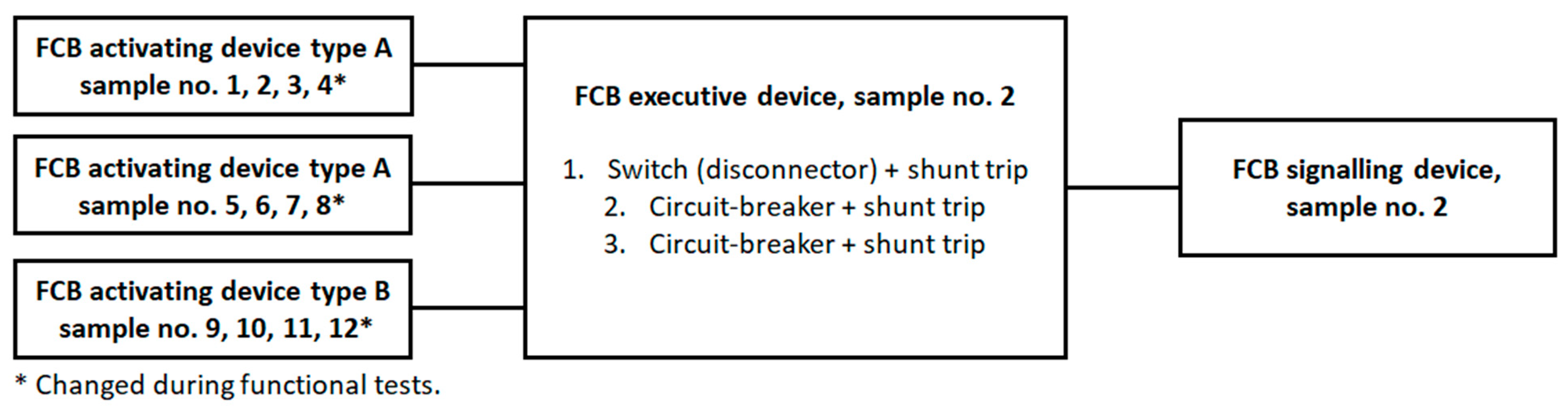
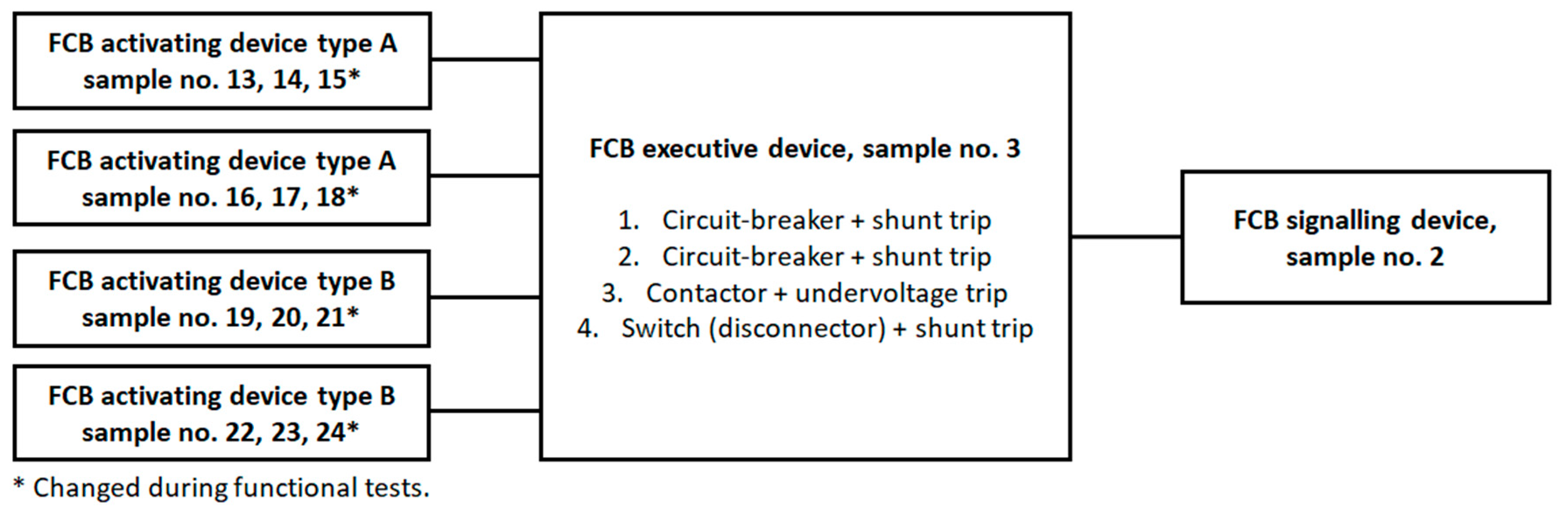
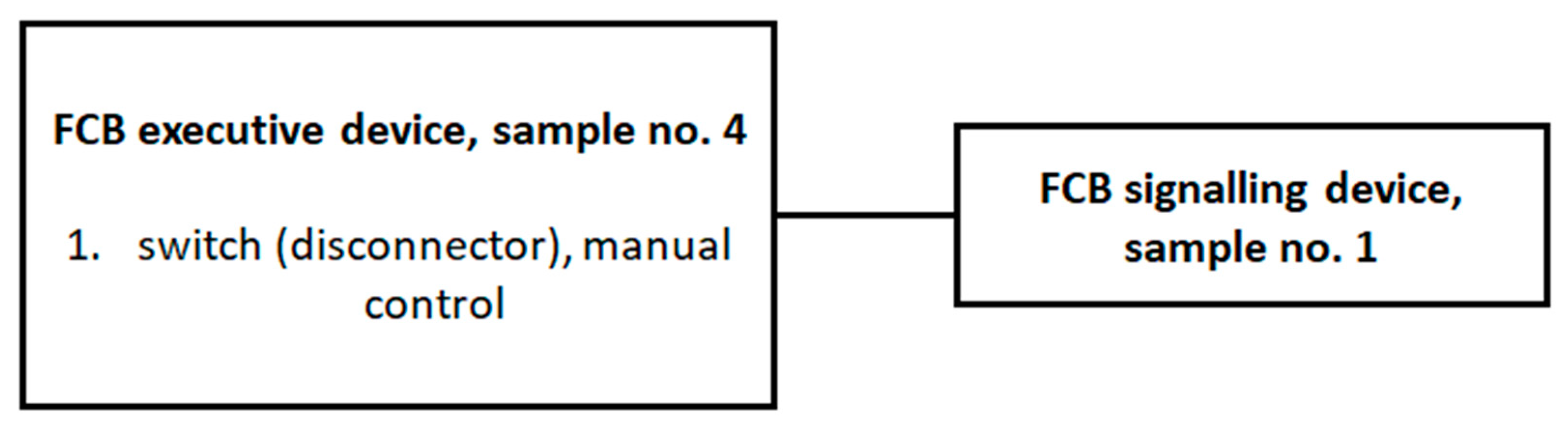
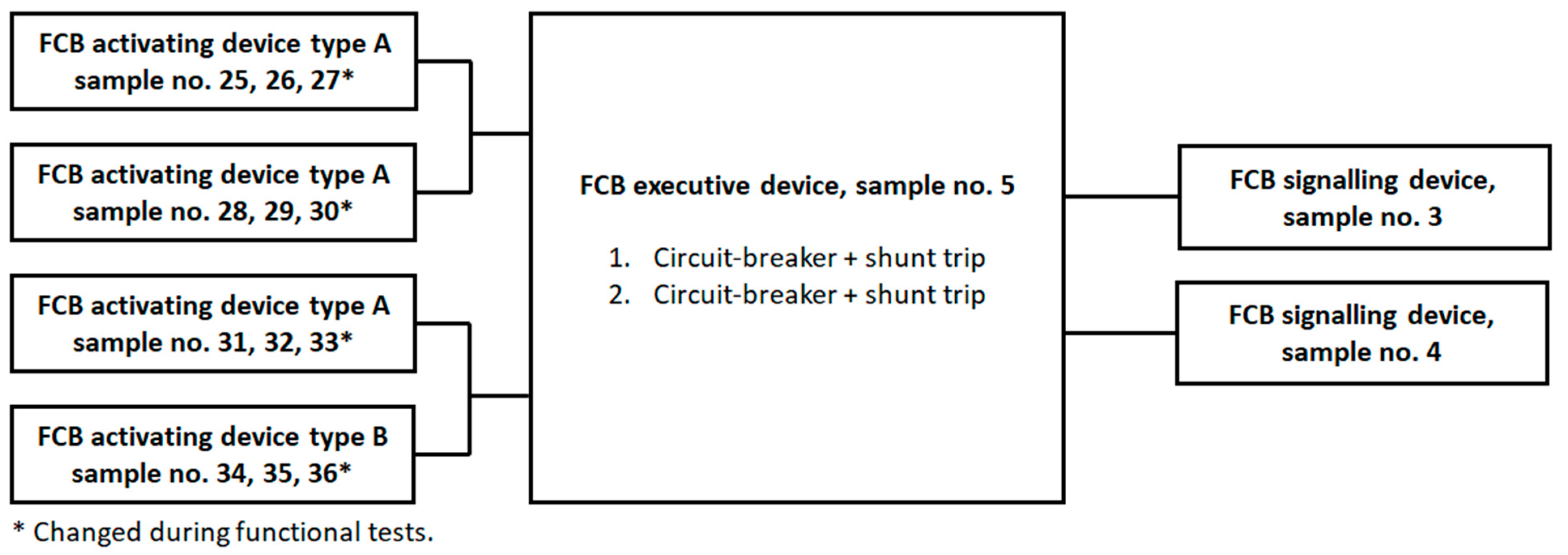
| Sample No. | Rated Voltage of the Main Circuit to Be Disconnected [V] | Rated Current of the Main Circuit [A] | Type of Actuator | Type of Trigger | Rated Voltage of the Trigger [V] | Battery as Backup Power | Delay in Device Operation [s] | Output to the BMS (Building Management System) |
|---|---|---|---|---|---|---|---|---|
| 1 | 230/400 V AC | 50 | FCB1—switch (disconnector) FCB2—circuit-breaker | None (manual control) | None (manual control) | Not | Not | Not |
| 2 | 230/400 V AC | 63 | FCB1—switch (disconnector) FCB2—circuit-breaker FCB3—circuit-breaker | FCB1—shunt trip FCB2—shunt trip FCB3—shunt trip | 24 V DC 230 V AC 230 V AC | Yes | Yes (5 s) | Not |
| 3 | 230/400 V AC | 63 | FCB1—circuit-breaker FCB2—circuit-breaker FCB3—contactor FCB4—switch (disconnector) | FCB1—shunt trip FCB2—shunt trip FCB3—undervoltage trip FCB4—shunt trip | 230 V AC 230 V AC 230 V AC 230 V AC | Not | Yes (5 s) | Yes |
| 4 | 230/400 V AC | 100 | FCB1—switch (disconnector) | None (manual control) | None (manual control) | Not | Not | Not |
| 5 | 230/400 V AC | 50 | FCB1—circuit-breaker FCB2—circuit-breaker | FCB1—shunt trip FCB2—shunt trip | 24 V DC 24 V DC | Yes | Not | Not |
| 6 | 230/400 V AC | 63 | FCB1—switch (disconnector) | None (manual control) | None (manual control) | Not | Not | Not |
| Sample No. | Nominal Supply Voltage [V] | LED Rated Power [W] | Type of Cable for Connection to FCB Executive Device |
|---|---|---|---|
| 1 | 230 V AC | 5 | 2 × 1.5 mm2 |
| 2 | 24 V DC | 2 | 2 × 1.5 mm2 |
| 3 | 24 V DC | 5 | 2 × 2.5 mm2 |
| 4 | 24 V DC | 1 | 2 × 2.5 mm2 |
| Sample No. 1 | Type of Switch | Type of Switching Element NO (Normal Open) or NC (Normal Close) | Nominal Supply Voltage [V] | Type of Cable for Connection to FCB Executive Device | Is Cable for Connection to FCB Executive Device Monitored (Short-Cut or Interruption Signalling)? |
|---|---|---|---|---|---|
| 1, 2, 3, 4, 5, 6, 7, 8 | A | NO | 24 V DC | 5 × 1.5 mm2 | Yes |
| 9, 10, 11, 12 | B | NO | 24 V DC | 5 × 1.5 mm2 | Yes |
| 13, 14, 15, 16, 17, 18 | A | NO | 230 V AC | 5 × 2.5 mm2 | Not |
| 19, 20, 21 | B | NC | 230 V AC | 5 × 2.5 mm2 | Not |
| 22, 23, 24 | B | NO | 230 V AC | 5 × 2.5 mm2 | Not |
| 25, 26, 27, 28, 29, 30, 31, 32, 33 | A | NO | 24 V DC | 5 × 2.5 mm2 | Yes |
| 34, 35, 36 | B | NO | 24 V DC | 5 × 2.5 mm2 | Yes |
| Parameter | Marking | Dimensions |
|---|---|---|
| Height of the faceplate | a | 85 ≤ a ≤ 135 mm |
| Width of the faceplate | b | 85 ≤ a ≤ 135 mm |
| Height-to-width ratio | a/b | 0.95 ≤ a/b ≤ 1.05 |
| Height of the operating area | c | 0.5 × a ± 10 mm |
| Width of the operating area | d | 0.5 × a ± 10 mm |
| Height-to-width ratio | c/d | 0.95 ≤ c/d ≤ 1.05 |
| Parameter | Activating Devices | Signalling Devices | Executive Devices | Test Method and Test Equipment According to | |||
|---|---|---|---|---|---|---|---|
| Environmental class | 1 | 2 | 1 | 2 | 1 | 2 | - |
| Operating temperature range [°C] | −10 ÷ +55 | −25 ÷ +75 | −5 ÷ +40 | −25 ÷ +75 | −5 ÷ +40 | −25 ÷ +75 | IEC 60068-2-1:2007 [24] and IEC 60068-2-78:2012 [25] Weisstechnik Climatic chamber 1.8 × 1.5 × 1.5 m |
| Maximum relative humidity [%] | 93 ± 3 | IEC 60068-2-78:2012 Weisstechnik Climatic chamber 1.8 × 1.5 × 1.5 m | |||||
| Possibility of installation indoor (I)/outdoor (O) | I | O | I | O | I | O | - |
| IP degree of protection of the enclosure | IP30 | IP54 | IP30 | IP54 | IP30 | IP54 | IEC 60529:1989 [26] ED&D ϕ2.5 mm tool, ITS dust chamber ED&D spray nozzle |
| Vibration (operational) | Frequency range (10 ÷ 150) Hz, Acceleration amplitude 0.1 g Number of axes 3, Rate of frequency variation 1 octave/min, Number of frequency variation cycles for axis 1 | IEC 60068-2-6:2007 [27] OTSTechnik Vibration test table 1.2 × 1.2 m | |||||
| Vibration (endurance) | Frequency range (10 ÷ 150) Hz, Acceleration amplitude 0.5 g Number of axes 3, Rate of frequency variation 1 octave/min, Number of frequency variation cycles for axis 20 | IEC 60068-2-6:2007 OTSTechnik Vibration test Table 1.2 × 1.2 m | |||||
| Mechanical impact (operational) | Impact energy (0.5 ± 0.04) J, Number of impacts on available point 3 | IEC 60068-2-75:2014 [28] PTL-Instruments Impact hammer | |||||
| Shock (operational) | Pulse shape: semi-sinusoidal, pulse duration: 6 ms, maximum acceleration: 10 × (100–20 M) m/s2 Number of strokes per axis: 6. Number of pulses per axis: 3 | - | IEC 60068-2-27:2008 [29] Shaker on OTSTechnik vibration test table 1.2 × 1.2 m | ||||
| Corrosive atmosphere SO2 (endurance) | SO2 concentration by volume (25 ± 5) ppm, Temperature (25 ± 2) °C at (95 ± 3)% humidity, Exposure time 21 days. | - | SO2 concentration 0.67 Vol.-% 1 cycle stage Temperature 40 ± 3 °C Humidity approx. 100% Time 8 h 2nd cycle stage Temperature 23 ± 5 °C Humidity ≤ 75% Time 16 h Number of cycles 20 cycles | - | SO2 concentration 0.67 Vol.-% 1 cycle stage Temperature 40 ± 3 °C Humidity approx. 100% Time 8 h 2nd cycle stage Temperature 23 ± 5 °C Humidity ≤ 75% Time 16 h Number of cycles 20 cycles | ISO 22479:2019 [30] VLM Corrosion chamber 1.8 × 1.2 × 1.2 m and IEC 60068-2-42:2003 [31] Weisstechnik Corrosion chamber 1.8 × 1.5 × 1.5 m | |
| Sample No. | Control | Main Part of the Executive Device | A Type of Trigger for the Executive Device | Minimum Trigger Voltage [V] | Start-Up Time of the Executive Device [s] (max. 10 s) | Was There No Permanent Arc or Flashover between the Poles or between the Poles and the Base during the Tripping Test? | Damage after Environmental Tests | Damage after the EMC Tests | Obtained IP Degree of Protection of the Housing 3—ϕ2.5 mm Tool Protected 4—Splashing of Water 5—Dust Protected |
|---|---|---|---|---|---|---|---|---|---|
| 1 | Manual | FCB1—switch (disconnector) FCB2—circuit-breaker | None (manual control) | None (manual control) | 4 | Not | No damage | No damage | IP54 |
| 2 | Remote | FCB1—switch (disconnector) FCB2—circuit-breaker FCB3—circuit-breaker | FCB1—shunt trip FCB2—shunt trip FCB3—shunt trip | 23.8 V DC 220 V AC 219 V AC | 3 | Not | No damage | No damage | IP30 |
| 3 | Remote | FCB1—circuit-breaker FCB2—circuit-breaker FCB3—contactor FCB4—switch (disconnector) | FCB1—shunt trip FCB2—shunt trip FCB3—undervoltage trip FCB4—shunt trip | 219 V AC 218 V AC 218 V AC 221 V AC | 8 | Not | No damage | No damage | IP54 |
| 4 | Manual | FCB1—switch (disconnector) | None (manual control) | None (manual control) | 2 | Not | No damage | No damage | IP30 1 |
| 5 | Remote | FCB1—circuit-breaker FCB2—circuit-breaker | FCB1—shunt trip FCB2—shunt trip | 23.5 V DC 23.4 V DC | 3 | Not | No damage | No damage | IP30 |
| 6 | Manual | FCB1—switch (disconnector) | None (manual control) | None (manual control) | 2 | Not | No damage | No damage | IP30 |
| Sample No. | Optical Signalling of the Executive Device Activation | Damage after Environmental Tests | Damage after the EMC Tests | The Obtained IP Degree of Protection of the Housing 3—ϕ2.5 mm Tool Protected 4—Splashing of Water 5—Dust Protected |
|---|---|---|---|---|
| 1 | Yes | No damage | No damage | IP54 |
| 2 | Yes | No damage | No damage | IP30 |
| 3 | Yes | No damage | No damage | IP54 |
| 4 | Yes | No damage | No damage | IP54 |
Disclaimer/Publisher’s Note: The statements, opinions and data contained in all publications are solely those of the individual author(s) and contributor(s) and not of MDPI and/or the editor(s). MDPI and/or the editor(s) disclaim responsibility for any injury to people or property resulting from any ideas, methods, instructions or products referred to in the content. |
© 2024 by the authors. Licensee MDPI, Basel, Switzerland. This article is an open access article distributed under the terms and conditions of the Creative Commons Attribution (CC BY) license (https://creativecommons.org/licenses/by/4.0/).
Share and Cite
Popielarczyk, T.; Stępień, P.; Chmiel, M.; Iwańska, M. Tests of Fire Circuit Breakers (FCBs) to Assess Their Suitability for Use in Construction Objects. Electronics 2024, 13, 1633. https://doi.org/10.3390/electronics13091633
Popielarczyk T, Stępień P, Chmiel M, Iwańska M. Tests of Fire Circuit Breakers (FCBs) to Assess Their Suitability for Use in Construction Objects. Electronics. 2024; 13(9):1633. https://doi.org/10.3390/electronics13091633
Chicago/Turabian StylePopielarczyk, Tomasz, Paweł Stępień, Michał Chmiel, and Marta Iwańska. 2024. "Tests of Fire Circuit Breakers (FCBs) to Assess Their Suitability for Use in Construction Objects" Electronics 13, no. 9: 1633. https://doi.org/10.3390/electronics13091633
APA StylePopielarczyk, T., Stępień, P., Chmiel, M., & Iwańska, M. (2024). Tests of Fire Circuit Breakers (FCBs) to Assess Their Suitability for Use in Construction Objects. Electronics, 13(9), 1633. https://doi.org/10.3390/electronics13091633