1. Introduction
Intelligent solutions utilising unmanned aerial vehicles (UAV) are emerging in various domains such as wireless sensing [
1], payload delivery [
2], precision agriculture [
3] and search and rescue operations [
4]. Moreover, with the current trend of automation, sensing, and information exchange within Industry 4.0 environments, UAV-based applications are also finding their place in construction, mining, agriculture and logistics industries, especially for resource tracking and operational monitoring using aerial imagery. UAV-based solutions are particularly beneficial in large infrastructure-deficient environments as they offer ease of deployment, quick access to ground-truth data, and higher reachability and coverage [
5,
6]. Furthermore, autonomous or semi-autonomous UAV-based solutions could facilitate many industry-specific audits such as progress monitoring, resource and safety inspections, environmental hazards, and many more. Although integrating a multi-UAV based visual sensing and monitoring system has many benefits, developing such a system is challenging. A few of those challenges include (1) monetary budget constraints which limit the number of deployed UAVs, (2) limited battery of UAVs restricting the observation span, (3) limited on-board processing capabilities of UAVs which necessitates online offloading of data, and (4) limited connectivity for data gathering and offloading tasks in infrastructure-deficient environments that requires efficient trajectory planning. The computationally intensive nature of the data collection task and limited on-board computation of UAVs impede the deployment of such solutions to collect and/or process data within large infrastructure-deficient sites, such as tracking the progress of complex construction projects. Hence, efficient multi-UAV mechanisms to collect and offload data from the field or points of interests (PoIs) to the backend system (cloud) are required to leverage the advantages of multi-UAV systems further. To address the above-mentioned challenges, a feasible solution could be the adoption of a heterogeneous multi-UAV framework.
UAVs can also be considered as integrated sensing and communication platforms for providing mobile edge computing services [
7,
8,
9]. The edge-based UAV platform could be flexible and cost-effective for computational and data-offloading tasks in infrastructure-deficient environments. Furthermore, with the optimal trajectory design of an edge-based access platform, the overall coverage of the PoIs can be improved. Thus an Access UAV (
) platform can be optimized for data collection, basic data processing, and data offloading to the cloud within infrastructure-deficient environments. However, if the PoIs are arbitrarily distributed in 3D space such as the monitoring points in under-construction projects, the maneuverability of the UAVs becomes challenging. UAVs that can be more agile by design are therefore better suited to reach arbitrary locations quickly and safely. Furthermore, such agile UAVs can carry different sensors such as multi-spectral cameras, near-infrared cameras, etc. to collect the requisite data from the locations. Hence, instead of overloading the
with data collection and offloading tasks, it would be prudent to segregate the UAV functions to optimize them for specific tasks. In this paper, we introduce the Inspection UAVs
() that are morphologically different from the
, as they are smaller and more flexible to maneuver at lower heights. The
act as a mobile visual sensing platform to collect visual data from different locations in the environment.
can be considered mobile sensors scattered throughout the environment. The
thus need to locate these dynamically moving
in order to collect data from them.
Another problem is the buffer overflow of UAVs in data collection and offloading tasks. The limited on-board processing capability and shared bandwidth to transfer data leading to the overall system’s instability. In addition, the varying data traffic and continuous movement of UAVs make it challenging to stabilize the system in a deterministic manner. Researchers have used online Lyapunov optimization [
10] to address such system instabilities. Lyapunov optimization considers the stability of a system with time-varying data and optimizes the time averages of the system utility and queue backlogs.
In this study, we address the challenges of deploying a heterogeneous multi-UAV system comprising a single UAV access platform called the Access UAV () and multiple Inspection UAVs () for dynamic data collection in infrastructure-deficient environments. We propose a Distance and Access Latency Aware Trajectory (DLAT) of the by considering the fair access schedules of the dynamically moving . In addition, to address system instabilities due to queue backlogs, the proposed solution employs a Lyapunov-based online optimization approach. The overall problem has been formulated as minimizing the total energy consumption of the system. Furthermore, as the set of and operate independently without any central entity, their coordination is ensured through a message-based estimation mechanism.
The contributions of this research are fourfold, which are summarised as follows:
An optimization model has been proposed for optimal trajectory planning of to fairly access the dynamically moving in different time slots. The optimization model focuses on minimizing the distance travelled and generating a fair access schedule of .
From an applications point of view, this research focuses on trajectory optimization of the to consider the limited battery constraint and the distance from the location of battery replenishment unit at the site.
Further, a model based on the Lyapunov based online optimization framework is proposed to minimize the energy consumption and the queue backlog of and with limited storage capacity.
Finally, extensive numerical experiments are conducted to evaluate the efficiency and performance of the proposed framework against multiple baselines.
The rest of the paper is organised as follows:
Section 2 summarises the related literature on edge based UAV applications.
Section 3 presents the proposed multi-UAV framework and the system model. The overall system objective is discussed in
Section 4.
Section 5 and
Section 6 discuss the access latency aware trajectory optimization and Lyapunov based system stability, respectively.
Section 7 and
Section 8 discuss the experiments and results. Finally,
Section 9 concludes the paper.
2. Related Work
Various studies have emphasized that trajectory planning of UAVs is an integral component of the UAV-based inspection and monitoring applications [
11,
12]. In [
13], the authors presented the reconstruction of a 3D model and highlighted the importance of UAV trajectories for computer vision techniques to reconstruct the 3D structure accurately. In [
14], the authors discussed how MEC can be divided into different architectures based on the role of UAVs, which could be users, computing entities, or data relay entities. The UAV-enabled MEC system is commonly employed in different scenarios to improve user experience and service availability or to increase the system’s efficiency. The trajectory optimization of UAVs is an integral part of such MEC systems as it affects the energy consumption of the system and the service schedule of static or dynamic sensors. UAVs could be deployed to relay data further or provide partial computing to improve the system overall quality of service (QoS). In [
15], multiple UAVs were deployed for data relay task from mobile devices to the BS. The overall objective was to minimize the energy consumption of mobile devices by jointly optimizing the task scheduling and UAV trajectories in resource-constrained environment. Using a different approach, Ref. [
16] proposed a single UAV-mounted cloudlet to serve a set of mobile users. The overall framework minimizes the energy consumption of mobile users, while optimizing the trajectory of the UAV-mounted cloudlet. The work of Xu et al. [
17] also considered the multi-UAV based computing framework to minimize the latency of mobile device data relay task either by on-board computing or relaying to BS. In [
18], a hierarchical multi-coalition UAV MEC network was discussed where the resource-constrained UAVs could offload task to other UAVs with high computational resources to improve the overall system efficiency. However, the authors did not consider the queue optimization, dynamic access of UAVs and challenges of an infrastructure-deficient environment as modelled in our work. In [
19], authors focused on minimizing the weighted sum of energy consumption of UAV enabled MEC system. They performed joint optimization of computation resource scheduling, bandwidth allocation to user equipment (UEs), and trajectory optimization of UAV-based edge servers with static ground sensors. The advantage of using multiple UAVs in the MEC system is further studied in the work of Diao et al. [
20], where the effects of joint optimization of trajectories of multiple UAVs to improve the system metrics were considered. However, the dynamic evolution of the data queues of the UAV-based MEC system could alleviate the problem of queue stability and data offloading.
The authors in [
21] addressed the stability issues with a Lyapunov-based joint resource optimization of bandwidth usage, processing power consumption, and transmission power. Zhang et al. [
22] presented a complex system within a dynamic environment that involves joint optimization of the computation resources of the multiple mobile users, UAV-BS, and trajectory optimization. The authors in [
23] discussed a UAV-assisted mobile edge computing framework that jointly addressed energy minimization, trajectory optimization, CPU frequency and offloading schedule. In [
24], author considered the completion time of the task along with the energy minimization and trajectory optimization of a UAV. One significant difference between our work and those reviewed in the literature is the estimation of the location of dynamic sensors (i.e.,
). This problem brings another challenge of coordination among
and
in the absence of ubiquitous connectivity with a limited battery. The proposed solution in this study attempts to solve both problems.
The literature also discusses the network scheduling problem along with trajectory scheduling for UAV-based MEC. In [
25], authors developed a hierarchical MEC system considering online optimization of computational resources and reinforcement learning based trajectory optimization of multiple UAV-BSs for collecting data from a set of static sensors. In [
26], a sense and send transmission protocol was proposed using multiple UAVs in a cellular network using an iterative trajectory sensing and scheduling algorithm. However, this approach does not consider distributed and multi-layer interaction of UAVs to collect and offload data with limited connectivity. In [
27], the authors employed reinforcement learning for sensing and sending information using a decentralized setup for multiple UAVs, however, their work did not consider the multi-layer UAV network with limited connectivity. As apparent from the literature, resource scheduling in multi-UAV based solutions is a challenging task, particularly in an infrastructure-deficient environment with limited connectivity. Therefore, the dynamic deployment of mobile UAVs either to collect data or relay data to the cloud could mitigate the issues of progress tracking and job monitoring in industrial settings and aid in the performance of project deliveries. This paper proposes a solution for end-to-end data offloading in large infrastructure-deficient environments using a hierarchical multi-UAV system.
3. System Model
This section presents the key components of the proposed multi-UAV framework. The system consists of heterogeneous UAVs, including a set of N Inspection UAVs (
) and a single UAV Access Platform (
).
s are smaller in size and more agile. They collect visual data from a set of k Point of Interests (PoIs) denoted as
. Because the framework considers infrastructure-less environments, limited Access Points (APs) available for cloud connectivity. Further,
possess a limited connectivity range, making it difficult to transfer data directly to the cloud.
, which is larger in size and possesses higher computational capabilities, coordinates with the
to collect data. We assume that the
always maintains a constant height, thus its trajectory lies in a horizontal plane.
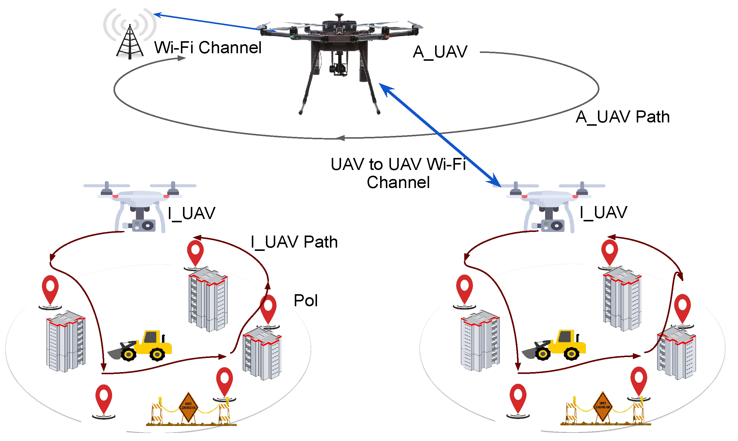
Figure 1 shows a high level overview of the system under consideration with
tasked to collect data from the PoIs, whereas the
collects data from the dynamically moving
and relay it to the cloud. The notations used in this study are given in
Table 1.
3.1. Communication Channel
The communication between
and
(A2A channel) has a limited range and capacity. This work assumes that the achievable data transmission rate of the
in a given time slot as
. The communication channel between
and
involves both line-of-sight (LoS) and non-line-of-sight (NLoS) links as PoIs can be distributed vertically and longitudinally. Furthermore, the shadowing effect is also considered due to obstructions caused by buildings and other structures in the surroundings [
28,
29]. The path loss of a link is given as follows:
where
is a shadowing factor that is indirectly proportional to the altitude of the PoI,
and
is the path loss exponent. The probability of LoS link,
, depends on the angle of elevation and environmental constraints (
and
) as given in Equation (
2):
The average path-loss is calculated as:
In this work, we have assumed Wi-Fi technology without a fixed access point for emergency or infrastructure deficient scenarios [
30]. The network of
and
provides connectivity to send collected data from PoIs to the cloud.
3.2. Data Gathering Process
Each PoI () is a tuple (), where specifies the amount of data (e.g., images) to be collected and denotes the 3D coordinates of the PoI. The sequence of PoIs to be visited is provided to the and the same is also shared with the . During the traversal along the sequence of PoIs, if the buffer of any of the overflows then that waits at the same PoI until its data is offloaded.
In order to gather and offload data, the
communicates with a single
in a time slot. Let us denote the data gathered by each of the
in a time slot
t by
. Let
be the queue of the
and
denotes the amount of data offloaded to the
by the
in time slot
t. The recursive equation to update the
is as follows:
Let
be the queue of the
where
accepts the data from the selected
in the time slot
t. The following equation updates
recursively:
where
is the amount of data offloaded to the cloud by the
in time slot
t.
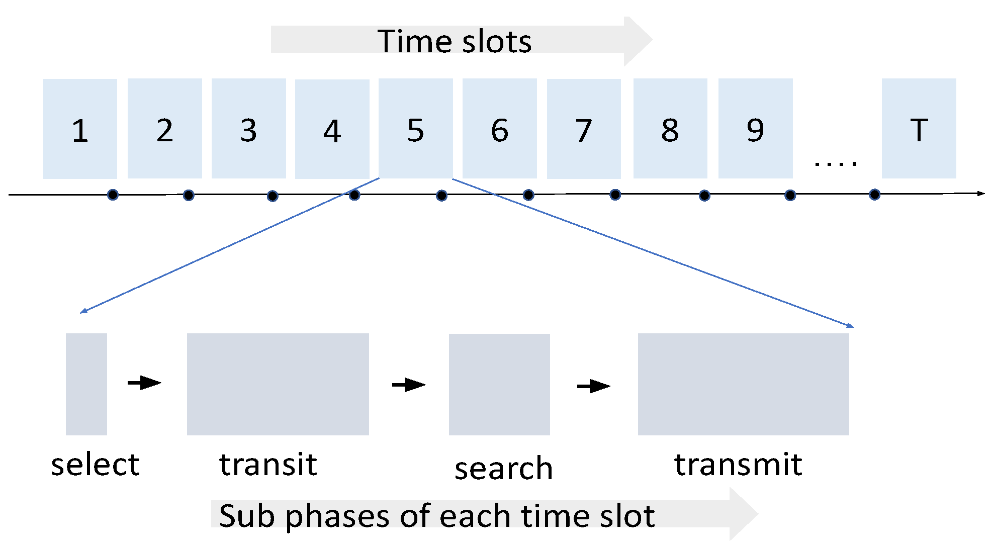
Figure 2 shows the different functions performed by an
in a single time-slot. The decision function takes negligible time to decide on the next
for data gathering, followed by the transition function where
takes
time to move near the next possible location to connect with the chosen
. The search function (
) estimates the location of the selected
based on the queue and position estimation algorithm given in Algorithm 1. The bound on the maximum time required to estimate the position of
is discussed in
Section 5.1. Finally, the data transmission function establishes the successful communication with the
(if it is not shadowed). The sequence of the functions mentioned above is repeated for every time slot. The next section describes the objective of the system and formulates it as an optimization problem.
| Algorithm 1 Estimated position and queue length of |
Initialization: ← - = last_accessed_position of = last_accessed_buffer curr_location_data = data left at last_accessed_position of Modes = Min or Max if Modes == Min then end if if Modes == Max then end if for alldo for all do while do if then if curr_location_data is not collected then = last_accessed_position last_accessed_buffer+data_at_current_loc else = next_position = last_accessed_buffer+ or if Mode == Min then else end if end if else = last_accessed_position = last_accessed_buffer break end if end while return, , , end for end for
|
5. Distance and Latency Aware Trajectory (DLAT) Optimization
Flexible and dynamic trajectory planning of is crucial to applications where terrestrial communication infrastructure is missing. As already mentioned, the position of s changes in every time-slot since they move through different PoIs to collect data. The ’s trajectory needs to be planned so that it can connect and access an in a time-slot before the ’s queue overflows. Whenever an ’s queue gets full, it does not move to its next designated PoI. Instead, it sojourns at the same PoI until it can offload its data to the and free up the queue space. In order to choose one of the s to gather data, the would require the real-time information about the queues of all s in each time-slot. This information is not available a priori due to the dynamic nature of the system queues. We use a message passing based approach for estimating the queues of s to make a selection. Further, the trajectory of the must be optimized to consume minimal energy.
The trajectory optimization model of
optimizes the trade-off between the transition energy of
and the access latencies of all
s. In addition, this access latency based data offloading generates an access fair schedule for the
s to offload their data to the
. The access latency (
) of the
in the time-slot
t is the difference between the time of its last access by the
and the current time-slot. The distance and latency aware trajectory optimization of
is formulated as:
where the first constraint (23) signifies that the distance travelled within a time-slot is limited by the maximum velocity. Constraint (24) limits the time that has elapsed since the last access of
to be less than
. The constraint in (25) selects the
which has data to offload whereas (26) enforces the selection of only one of the
s in a time-slot. The selected
transmission power should be bounded as given in (27).
5.1. Estimating Position and Queue Length
The exact position and queue length of is not known to the a priori. The maintains the last access statistics of each using status messages. The track of status messages received over time helps in computing the position () and queue length () of s in a time-slot. The status message comprises of the remaining queue size at the time of access and the data to be collected at the current PoI. Moreover, the pre-computed trajectory of each provides the set of PoIs to be visited by each . Algorithm 1 describes the procedure to estimate the queue length of each in every time-slot.
5.2. Estimation of Search Time Bound
estimates the location of in each time slot using the last access statistics. It could search the set of candidate locations to locate the precise location of selected , which contributes to the search time. The bound on the search time depends on the data generation rate and the maximum buffer of as derived below.
Lemma 1. The search time to locate the exact location of with max buffer size is given as:where ϱ is the maximum distance between two consecutive PoIs in the possible set of locations to be searched and is the number of candidate locations for and data generation process at each PoI follows the normal distribution Proof. The time taken to find the location of
depends on the travel distance to cover the candidate PoI locations as given in Equation (
30).
By generality,
where
is the set of locations visited when each location has minimum data
to be collected whereas
is the set of locations when maximum data
is present at each location. As the memory of each
is bounded by
, it covers less number of locations for
as shown in Equation (
31). Similarly, the data collected in both the scenarios will be same as the maximum memory size is fixed. The candidate locations are defined as the locations starting at
and ending at
. Intuitively, the number of candidate locations
.
From the above derivation, the locations in search trajectory are influenced by data rate and maximum limit of memory size for
. The upper and lower limit of normally distributed data is given as
and
respectively. Thus Equation (
30) can be written as
□
To calculate the upper bound for Equation (
33),
is the distance between consecutive PoIs which could be calculated from the pre-calculated trajectory of
based on shortest path.
6. Energy Aware Data Offloading
The model presented in
P1 in
Section 4 is a stochastic optimization problem as the arrival of data in the system queue is stochastic. Using the online Lyapunov optimization algorithm, we solve the stochastic optimization in
P1 and jointly stabilize all queues by finding the optimal policy to access each
in each time-slot. The quadratic Lyapunov function, as given in Equation (
36) associates a scalar measure to the queues of the system. Further, the stability of the system is maintained by a guaranteed mean rate stability of the evolving queues as given in Equations (
34) and (
35).
where
consists of all system queues at a time t and
is quadratic Lyapunov function of system queues. The
Lyapunov drift corresponding to the above function is given as:
The Lyapunov drift plus a penalty function is minimized to stabilize the queue backlog of the system is given as:
where
V is a positive constant that controls the trade-off between Lyapunov drift and the expected system energy. A high value of parameter
V signifies more weight on minimizing the energy of the system at the cost of high queue backlog. Therefore,
V acts as a trade-off parameter between system energy and queue backlog. An upper bound on
can be derived as follows, (for details see [
10])
where
C is a deterministic constant.
As a result, the upper bound of the drift plus penalty function becomes
Hence, the original formulation
P1 can be reduced to
P3 which bounds the system’s drift to keep it stable.
As can be observed, the constraints in
P3 is a subset of the constraints in
P1. To further simplify the solution of the optimization formulation, we reformulate
P3 as two separate sub-problems provided the positions of
and
are fixed in a given time slot
t. The Lyapunov based online optimization is optimal for a stochastic system to derive the overall optimal solution [
33].
6.1. Optimization of Transmission Energies of I_UAVs
The first sub-problem deals with the optimization of parameters related to the
. The variables
, i.e., the position of
and the offloaded data
of the selected
are coupled in a particular time-slot. The fixed position of
decouples these variables. In the optimization model
P 3.1, the transmission energy is optimized for a single time-slot (
t) given the position of
:
The objective function in P 3.1 is a convex function. The first & second constraints are linear and the third constraint is upper bounded by a concave function. As a result, the stationary point of the objective function is found to be: .
6.2. Optimization of Transmission Energy of A_UAV
The second sub-problem deals with the optimization of the
parameters for the amount of data offloaded to the cloud at time
t. The updated optimization model is given as:
The model P 3.2 has a convex optimization objective subject to convex constraints to solve for the optimal transmission power of the . The stationary point of the optimization model is .
Thus, the derived stationary points of the optimization model using the Lyapunov optimization framework are calculated in every time-step to optimize the
A_
UAV trajectory and data-offloading tasks. The overall proposed solution approach is presented in Algorithm 2. Next, we discuss the experimentation setup for evaluating the proposed solution.
| Algorithm 2 Proposed Solution Approach |
Initialize: Trajectories of all and list of PoIs . Time: whiledo 1. Compute and offload as using P 3.2 2. Update 3. Using Algorithm 1 estimate the and 4. Select the to collect data using P2 5. Compute for using P 3.1 to offload data to 6. Update 7. end while
|
7. Experimentation
In this section, we present the simulation setup to validate the efficacy of our proposed Distance and Latency Aware Trajectory Optimization with Lyapunov based energy-aware data offloading followed by results and discussions. The simulation parameters are listed in
Table 2.
We have considered a 600 × 600 square meter area with PoIs spread along the region in disjoint clusters and at heights ranging from 70 to 80 m above the ground. All experiments are conducted for at least 30 times and the average of results are plotted. We sample 150 PoI locations uniformly randomly in three disjoint clusters. From a practical point of view of a multi-UAV system, we consider a system of three
with one
in all the simulation experiments. Each
is assigned to a cluster where
randomly choose a starting location within the cluster. The sequence of PoIs to be visited by each
is generated using the shortest path algorithm. Before proceeding to the next PoI, an
collects all the data (
) from that PoI. In the data collection process, an
may sojourn at the same PoI across multiple time-slots until all the data (
) of PoI is collected. For each PoI, the amount of data to be collected is modeled as a Gaussian distribution with a mean of 150 Kb and variance of 50 Kb. The
gets partial information about the data generated at each location so it could not accurately estimate the location of
in the next time slot; as a result, it has to search for candidate locations to access the selected
as discussed in
Section 5.1. The trade-off parameter
V ranges from 10 to
. The length of each time slot
is 25 s divided into different sub slots as shown in
Figure 2. The selection of
is assumed to take negligible time whereas transition may take up to 20 s. The search and transmit function takes total of 5 s. The maximum transmission power for
and
are 5 W and 2 W, respectively [
25]. The other simulation parameters are listed in
Table 2.
In order to validate the performance of our proposed approach, we compared our proposed approach with a set of baseline approaches on two broad categories of optimization parameters viz. Trajectory planning and Data offloading. We consider the following baseline approaches:
Distance Aware Trajectory planning (DAT): In this approach, the selects to access an based on the shortest distance from the current location in each time slot.
Round Robin based Trajectory planning (RR): In this approach, the accesses in sequential order in each time slot.
Maximum Transmission Power (MAX) data offloading: In each time slot, the and the operate at the maximum transmission power to offload data.
The proposed approaches are as follows:
Distance and Latency Aware Trajectory Optimization (DLAT): In this approach, the selects the based on the minimum distance, with maximum bits to offload and access latency constraint as given in the trajectory optimization problem.
Hybrid Approach for Trajectory Scheduling (HDLAT): In this approach, the selects the based on the minimum distance and access latency constraint as given in the trajectory optimization problem up to a certain threshold of battery, i.e., 75% of the total battery. Beyond the threshold, the scheduling algorithm switches to the DAT strategy (proposed approach).
Lyapunov Optimization for data offloading: In each time slot, the and the calculate the optimal value of transmission energy using the Lyapunov Optimization.
Experiments were conducted by taking a combination of one of the approaches from both the categories: (1) DAT + MAX, (2) DLAT + MAX, (3) RR + MAX, (4) HDLAT + MAX, (5) DAT + Lyapunov, (6) RR + Lyapunov (7) DLAT + Lyapunov (proposed approach) and (8) HDLAT + Lyapunov.


