1. Introduction
The article concerns the analysis of processes and the operation of hybrid switches [
1,
2] related to the arcless switching off of short-circuit currents in power circuits operating in difficult environmental conditions [
3,
4]. In the conditions under consideration, the main cause of disruption of the power system operation is a dynamic short circuit, but one cannot omit such factors as vibrations, lightning, or changing weather conditions. Such conditions occur, among others, in ship electric power systems or electric traction railway systems [
4,
5]. Due to the fact that the operation of switching off short-circuit currents refers to emergency states and is essential for the operational safety of the considered power system, the devices performing these operations, usually hybrid switches, belong to the group which can be referred to as critical devices for electric power system operation.
Because the critical devices fulfill a vital role in the operation of the considered systems, they should ensure the reliability, safety and repeatability of the realized operations. A principal module of the hybrid circuit breaker is an electrodynamic propulsion–actuator, responsible for the safe and correct switching off of the controlled circuit.
In the solution presented in this article, an electrodynamic propulsion–actuator is realized as the inductive dynamic drive (IDD). The IDD (Figures 1 and 3) is an integral part of a current limiting interrupting device (CLID) (Figure 1a,b), in which this actuator works synchronously with semiconductor elements [
5,
6].
The discharge of the capacitor battery (of the IDD) occurs in a circuit of low resistance and inductance so that through the coil flows a large current generating a large magnetic field. A variable magnetic field induces (in the disc surface layer) eddy currents, which generate impulsive force (displacing disc) when interacting with the current coil. At this time, the energy-absorbing element (e.g., varistor) minimizes the short-circuit current to the value at which the drive, spacing the contacts apart, allows for the arcless switching off of the short circuit.
It follows that the electrodynamic actuator must be characterized by repeatability and a suitable duration of action [
7,
8,
9]. The necessity of complying with these requirements is a reason for the continuous research and study of the impact of influencing disturbing factors for electrodynamic actuator–propulsion operation. The undertaken research and study results from the aforementioned industrial application experiences include harsh environment applications such as sea or railway conditions on the one hand, and, on the other hand, laboratory investigations aimed at the further development of existing solutions. In some cases a malfunction of electrodynamic actuator operation consisting in a discontinuity of energy transfer from discharged capacitors to the drive coil has been noted. This phenomenon has been occurring randomly, so it can be considered a kind of hazard of electrodynamic actuator operation.
Basically, the trigger circuit (Silicon Controlled Rectifier –SCR thyristor or Insulated Gate Bipolar Transistor-IGBT) in the drive coil power supply circuit should generate an uninterrupted signal (Figure 4a), however in real industrial systems (e.g., industrial systems in sea conditions) the occurrence of such disturbances is inevitable, especially in the case of the appearance of a large short-circuit pulse (Figure 4b). Additionally, the results of the pilot experimental research concerning ultra-rapid drives also confirm the stochastic appearance of disturbing signals, that is, discontinuities in the energy transfer to the drive coil, understood as coil current flow interruption.
The aforementioned circumstances were a reason to order (by the CLID module users) the authors’ research team to carry out experimental research which would unambiguously explain the cause of the previously mentioned energy transfer discontinuities and the consequences of their affecting on the correctness of operation of the IDD actuator in the CLID module (
Figure 1).
In this context, a basic problem to solve is to identify the reasons and determine the conditions of occurrence of the hazardous operation of an electrodynamic propulsion–actuator, as well as to investigate the consequences of these phenomena and mitigation measures. A novelty of this paper concerns the carrying out of the experiment and simulation research, resulting in reasons explaining the incorrect operation of the hybrid switch drive, and elaboration of the authors’ new field–circumferential model of rectilinear propulsion, enabling the analysis of the electrodynamic actuator operation under discontinuous energy transfer to the drive coil. This analysis is related to and focused on the examination of a working hypothesis: in the real ultra-rapid drives, a random, stochastic disturbing signal can appear in a trigger circuit and cause discontinuities in the energy transfer to the drive coil. For a better understanding of the contents of this paper, a flow-chart of the investigation carried out is shown in
Figure 2, in order to effectively demonstrate the proposed experimental and simulation research.
To explain the reasons and nature of the appearing discontinuities, the standard example of the CLID device equipped with inductive dynamic drive (IDD) and supplied from the capacitor with a capacity of
C = 100 μF charged to the initial voltage value, which equals
Uc = 800 V, was used. The applied measurement system (
Figure 3a) enables the registration of the drive coil current and disc displacement. For the measurement system of the IDD (
Figure 3), experimental pilot research was carried out. This research confirmed the appearance of the discontinuous flow of the coil current. Simultaneously, a gate signal in the drive coil power supply circuit was registered. It was observed that the appearance of coil current discontinuity (Figure 5a) was accompanied by randomly appearing discontinuity of the gate signal current (
Figure 4b). Therefore, the previously-cited working hypothesis was formulated. In a further step, referred to by the authors an in-depth analysis, extended experimental research was continued to look for other values of capacitances
C and voltages
Uc that comply all the time with the condition of the constant value of the initial energy
E of the capacitor battery. Within the framework of an in-depth analysis, in parallel to physical experiments, a field–circumferential model of the IDD drive was built and applied. Due to this model, a simulation of the moment of an interruption appearance in the gate current circuit expressed by delay time Td, as well as an examination of the influence of this moment on the current continuity in the drive coil, and more, on the dynamic properties of the IDD drive expressed by disc displacement, was possible.
Following this chapter, the rest of this article is structured in this way:
Section 2 describes the experimental study of the IDD dedicated measurement system,
Section 3 presents the field circumferential model of rectilinear propulsion, and
Section 4, fundamental for this paper, is devoted to the analysis of an influence of discontinuous energy transfer on the electrodynamic propulsion–actuator dynamic properties. The last section is a conclusion of the study.
2. Experimental Study
The description of the measuring system (
Figure 3a), allowing for the registration of the coil current and the displacement of the drive (IDD) using the optical sensor (optimeter) was presented in detail in [
7,
8]. The power supply circuit of the coil is closed by controlled valve (transistor or thyristor with diode) so that one can conclude that the release of this valve occurs almost immediately after the detection of a short circuit. The gate circuit in the tested drive model can generate a continuous signal flowing in a short time of the whole process (less than a few milliseconds). Hence, it can be easily implemented as a (Resistive-Capacitive) RC circuit for discharging a small capacitor (
Figure 3b). On the other hand, in a laboratory environment, a contactor is often used to initiate the discharge of this gate circuit. As a result of many tests (pilot experimental research) carried out in the measurement system (
Figure 3), it turned out that the correct gate signal was obtained with a similarly random frequency (with similar probability distribution), as the disrupted signal (
Figure 4). The obvious explanation for this is the appearance of the contact bounce of the contactor. Such a disturbed gate circuit signal is also the cause of discontinuous energy transfer from the capacitor bank to the coil (red waveform
Figure 5a). At the same time, it should be emphasized that in industrial conditions, especially marine (e.g., stormy) conditions, such a disturbance of the gate control signal of low power at the moment of short-circuiting impulse may also appear during the operation of the CLID system, with a contactor-less solution.
Due to the modular design of the capacitor bank (
Figure 3a) it is possible to change the total capacitance (
C) of the capacitors, while maintaining the initial energy
E of the battery by changing the initial voltage
Uc accordingly:
where
C is the total capacitance of the capacitor battery, and
Uc is the initial voltage value.
Presuming that electrodynamic drive efficiency depends on the capacitance in a small measure, then on the basis of the energy conservation law (the electric field energy corresponds to the product of efficiency and disc kinetic energy), it might be supposed that the value of the total battery capacity used does not have a significant impact on the dynamic characteristics of the drive (maximal value of displacement in the given set time), if the condition of the initial energy of the capacitor bank is retained. However, the further experimental research carried out for a 10 times higher capacity of the
C capacitors and reduced (respectively for the condition
E =
Const.) voltage value showed that the drive disc reached a greater displacement range than previously (
Figure 5b). This time, the energy transfer maintained continuity, despite the occurrence of disturbances in the gate circuit in the initial period (
Figure 4b), which means that the disruption disappeared before the thyristor switched back on (blue waveform
Figure 5a). In order to clarify whether the increased value of the displacement range in case of the battery capacitance increase (at energy
E =
Const.) is caused by the continuity of energy transfer to the drive coil, further tests were carried out, both simulative using the new IDD model as well as experimental.
3. Field–Circumferential Model of Rectilinear Propulsion
In order to examine the above effect of the discontinuous transfer of energy from the capacitor on the dynamic properties of propulsion, it was decided to carry out simulation tests in the field model in which controlled switches in the power supply of the coil circuit will be able to close the circuit at a selected time. A 2D (two-dimensional) propulsion model was realized in the Maxwell program, which takes into account the movement of the disc under the influence of the electrodynamic interaction force. The elementary electrodynamic interaction force between the coil and the disc is proportional to the cross product of the current density and flux density generated by the coil current. Hence, the instantaneous force function
F(
t) is obtained on the basis of the following volume integral [
10,
11,
12,
13,
14].
Then the function of the disc displacement
x(
t) can be determined using the following formula:
Such an IDD drive model was implemented and described in detail in [
9,
15]. Due to the fact that the implementation of the circumferential part of the model existing so far makes it impossible to simulate discontinuous energy transfer, appropriate modifications have been made.
The main goals of IDD model modification are:
the field-circuit model of drive executed in the Maxwell program along with an accompanying external circuit containing controlled switches.
the simulation and analysis results in the coil current, force and the displacement drive for different moments of activation switches.
A model modified this way enables the simulation of a discontinuous coil current flow and discharging voltage of the capacitor battery, resulting in energy flow interruptions between capacitor and coil, in other words, discontinuity of the energy transfer.
The realization of the simulation research presented in this article is shown in diagram form in
Figure 6a.
By appropriately setting the control signal switches S_ON1 and S_ON2, simulation results of coil current, forces, and hence the disc displacements for the continuous and discontinuous energy transfer from the capacitor were obtained. The model constitutes half of the cross-section of the coil–disc system, therefore cylindrical symmetry of the drive was used (
Figure 6b). The number of meshing elements was limited to 20,000, into which the whole area was discretized, which was the guarantee of the convergence of the obtained results. As a boundary condition, a potential vector on the boundary area (region) with the value of zero was assumed.
Figure 6b shows a screen from the propulsion model executed in the Maxwell program representing half of the drive in the cylindrical system with meshing into elements. Magnetic field distribution (for the initial moment) shown in this figure presents a strong phenomenon of skin effect due to the rapidly increasing current. Since the coil in the model was associated with winding, then (in the Ansys–Maxwell program [
16,
17]) it is possible to attach to the external circuit. Parameters defining the dimensions of the coil and the disc of the drive as well as capacity of the capacitor battery are included in
Table 1. Because the model uses an object defined by the program as a coil, which must be linked to winding, inductance is calculated by the model in every numerical step.
In contrast to inductance, the resistance of the coil is not calculated by the Maxwell program, so it was required to be estimated, which was done on the basis of the formula where the coefficient
k includes the impact of the skin effect:
where
rc(ci) is the radius of
ci-th wire.
dwire is the wire diameter,
b0, β0 are the absolute value and argument of the modified first kind Bessel function,
b1, β1 are the absolute value and argument of the modified second kind Bessel function,
and
where ω is the current angular frequency, μ is the permeability, and γ
cu is the conductivity.
The external circuit was built in the Ansys_Maxwell_Circuit_Editor subprogram (
Figure 7a). After opening this sub-program the coil symbol appears as the first object, which represents the coil of the main program Maxwell. By including further elements we can create an outer circumference of the coil, which is then exported to the main model in Maxwell program. This circuit employs two parallel switches that are controlled by a periodic signal (
Figure 7b). The parameters of the signal, i.e., the rise time T
r and fall time T
f and the resistance value R
off and R
on of the switch in the off and on state in the block model (
Figure 7a), one can set in such a way that operation of these connectors will be similar to the actual valve, such as a thyristor or a transistor. In the present study, very short times (1 × 10
−15 s) were adopted for T
r and T
f, that is, it is assumed that both valves have similar, almost perfect dynamic properties. The on-time T
d of the first connector is set to zero, while the second connector on-time was adjusted depending on with what delay we want the capacitor to return the next portion of energy.
Preliminary simulation research for the validation of the IDD model has been compared with the experimental research for the propulsion parameters shown in
Table 1 (
Figure 8).This validation is based on the use of the field–circumferential model of rectilinear propulsion executed in the Maxwell program and the experiment made in the IDD measuring system presented in
Section 2 (
Figure 3a).
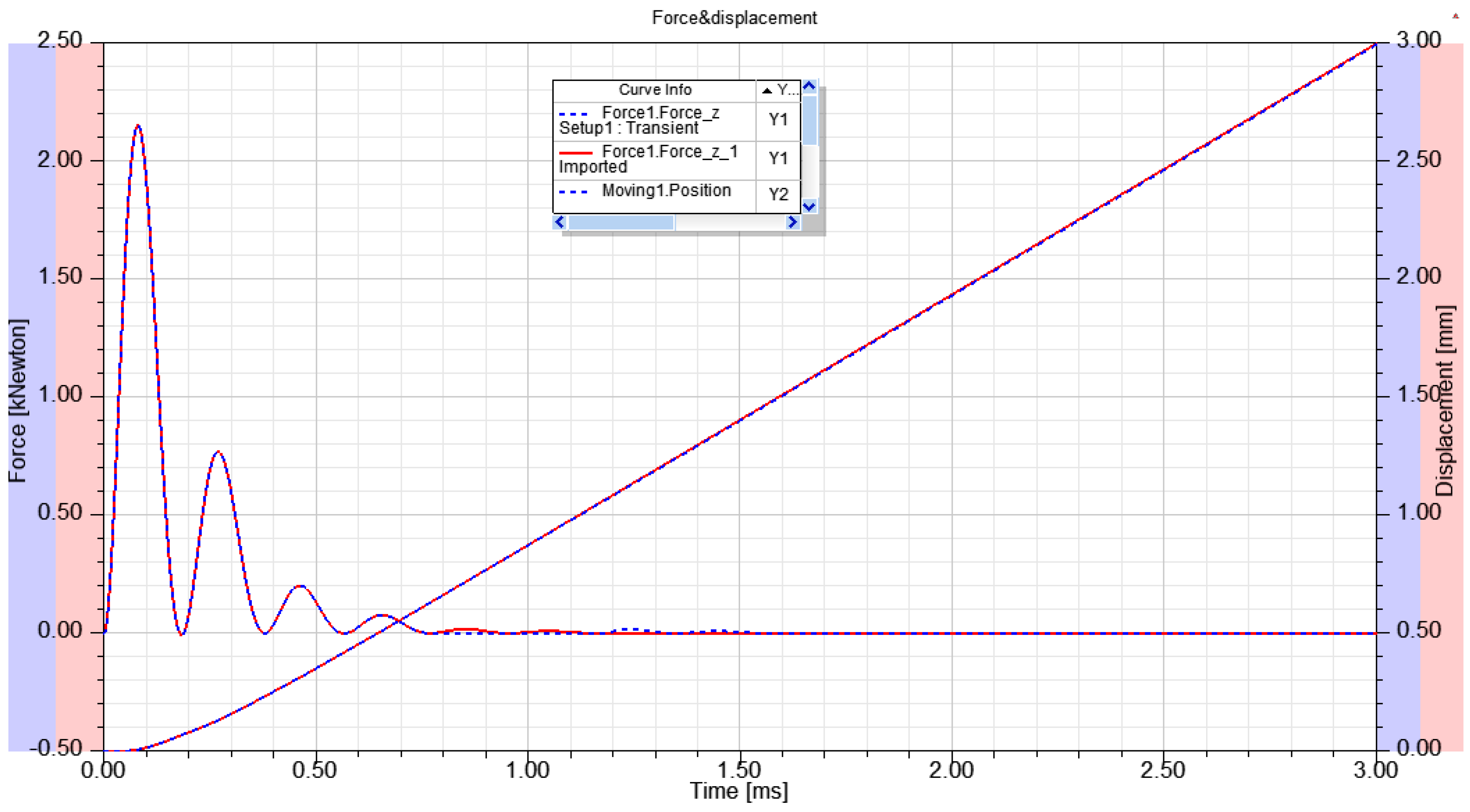
Figure 8a shows a comparison of the coil current waveform obtained in the field model with the course derived from the experiment with the bidirectional switch.
Figure 8b shows a similar comparison of the disc displacements received from the circumferential–field model and the experiment. The results illustrated in
Figure 8a,b are composed of two records, expressed by a solid line (experimental results) and a dash line (simulation results). The experiments and simulation research were carried out for the same capacity value
C = 100 μF and for the remaining IDD parameters listed in
Table 1.
Based on the observation of
Figure 8a,b it is to be said that the comparison of coil currents proves very good convergence and hence the correctness of the constructed field–circumferential model. In the case of displacements, one can see the difference in the waveforms in the initial phase of the movement (x < 1 mm), which can be explained by the fact that the presented drive model assumes, firstly, the ideal stiffness of its moving element (
disc) and, secondly, the lack of any vibrations of measurement system, which is unavoidable [
18].
4. Influence of Discontinuous Energy Transfer on Dynamic Properties of Propulsion
Further studies were performed using the built field–circumferential model according to the scheme illustrated in
Section 3 (
Figure 6a) and cover cases presented in
Table 2. Of the tests carried out for the present paper, three cases are shown in which the waveforms of the coil current, force and disc displacement for the continuous and discontinuous energy transfer from the capacitor were compared. The on-time (Td
1) of the first switch S_ON1 was set as zero (start simulation). The discontinuity was adjusted by the off-time (Pw
1) of the first switch S_0N1 and the on-time (Td
2) of the second switch S_0N2 (
Figure 7b). The exact values of the on and off times for the presented study (three cases) are shown in
Table 2.
In the beginning, one switch with a large Pw time ensuring an uninterrupted current throughout the range time was turned on. Zero points of coil current for this case allow us to determine the off-times of the first and the on-times of the second switch. First, the current waveforms for the normal operation of the bidirectional switch and the situation when the switch during experimental measurements was turned off after the fourth pulse current (counting positive and negative pulses), and then got turned on with a delay of two pulses (
Figure 9) were compared (Case 1).
The model in the Maxwell program allows us to determine the volume forces acting on each element into which the disc is split. Due to the cylindrical symmetry, all the forces acting on the disc have only two components: radial and axial. On the other hand, from the viewpoint of the movement of the rigid body, the resultant force has an axial component only.
Figure 10 shows the waveforms of the resultant axial forces and displacement corresponding to the continuous and discontinuous waveforms, i.e., the coil currents of
Figure 9 (Case 1). Slight differences in the waveforms of these forces actually explain the lack of differences in displacement waveforms (
Figure 10) and hence also the speeds. For Case 1,
Figure 9 additionally presents the waveform of the capacitor voltage, which shows that at the instant of current interruption, the capacitor had already given away 99% of the initial energy. The remaining 1%, which corresponds to the voltage 80V of the capacitor, as it turns out, has no significant impact on the force and hence on the displacement and speed of the disc.
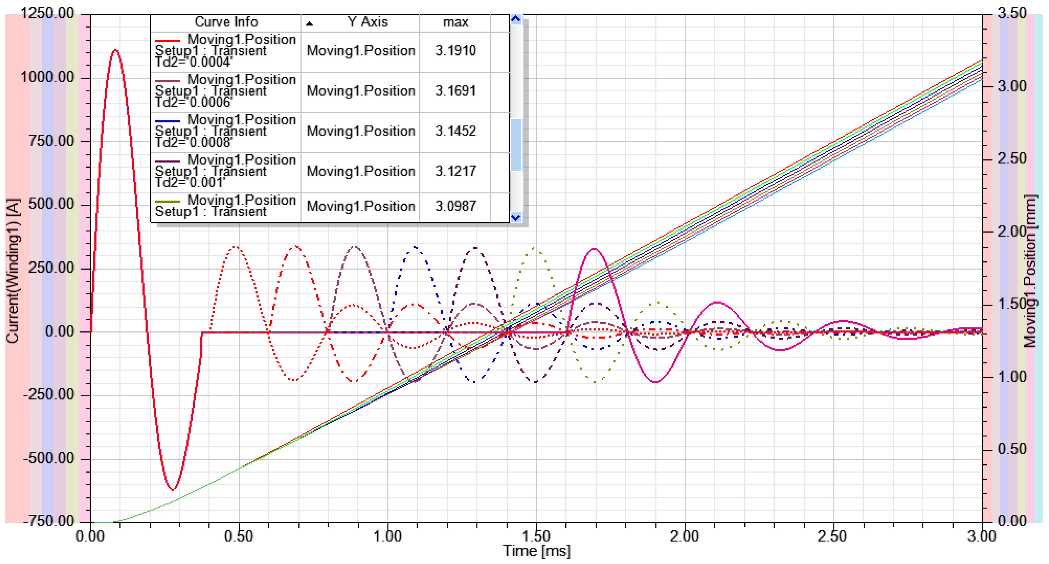
Given such a small amount of remaining energy in the capacitor, additional simulations determining the family of characteristics for the changing on-time (Td
2) of the second switch were performed (
Figure 11), (Case 2 from
Table 2).
Figure 11 shows a comparison of coil currents and corresponding displacements. This time one can see slight differences between the displacement waveforms, where the relative difference in the maximum range that the disc achieves after 3 ms between continuous and discontinuous cases does not exceed 4.5%.
The circuit hybrid breakers require reaching an adequate gap between the contacts, which must ensure irreversible turning off of the circuit in which the short-circuit took place. It is most often required that the distance between the contacts obtained in suitable time amounts to approximately 3 mm [
19,
20]. Generally, the aim is to make this time as short as possible. Finally, displacement trajectories were compared for two clearly differing capacitances (
C = 100 μF and
C = 1000 μF). The result of the simulation from
Figure 12 confirms (experimental results from
Figure 5b) that in the further part of the displacement, the greater range is reached by the waveform for a greater capacitance of the battery, despite the same initial energy of the capacitors. This effect undoubtedly results from the stronger influence of the skin effect for this configuration of the capacitor battery.


