A High-Voltage “Sen” Transformer: Configuration, Principles, and Applications


Abstract
:1. Introduction
2. Configuration of the HVST
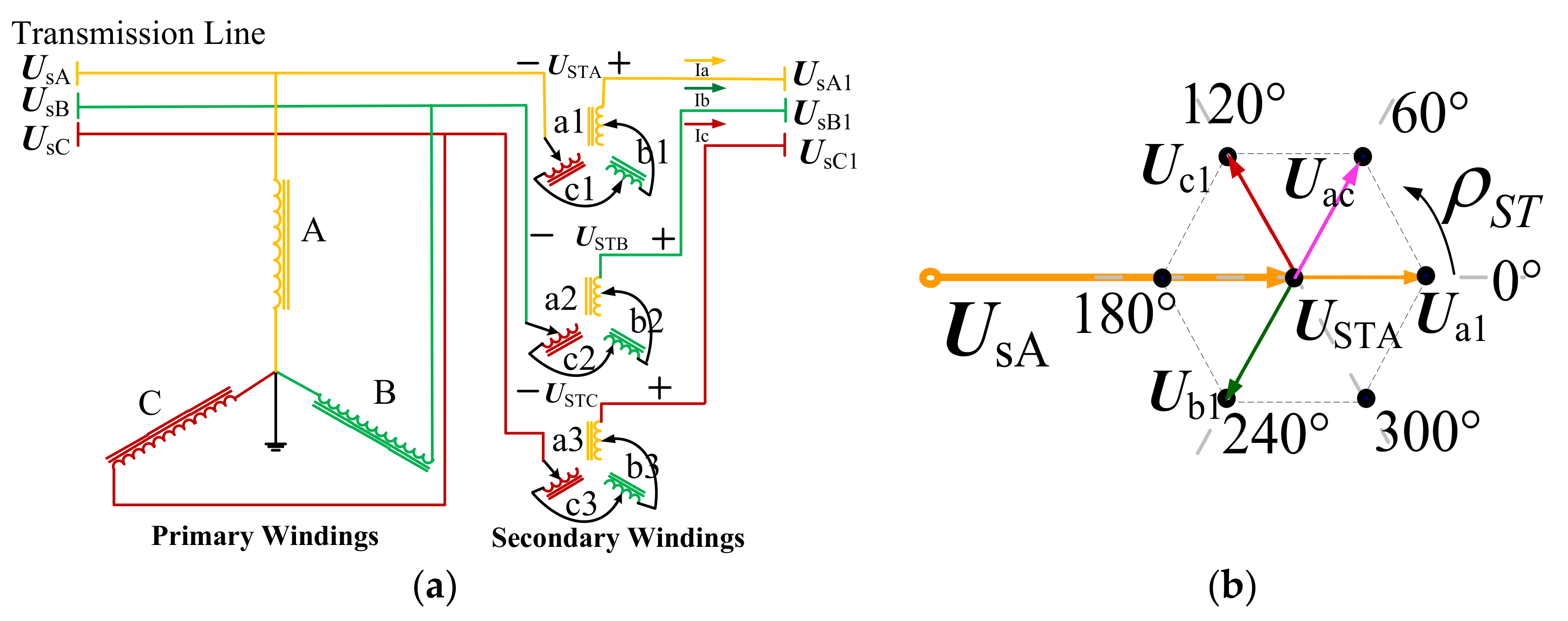
2.1. ST Configuration [13]
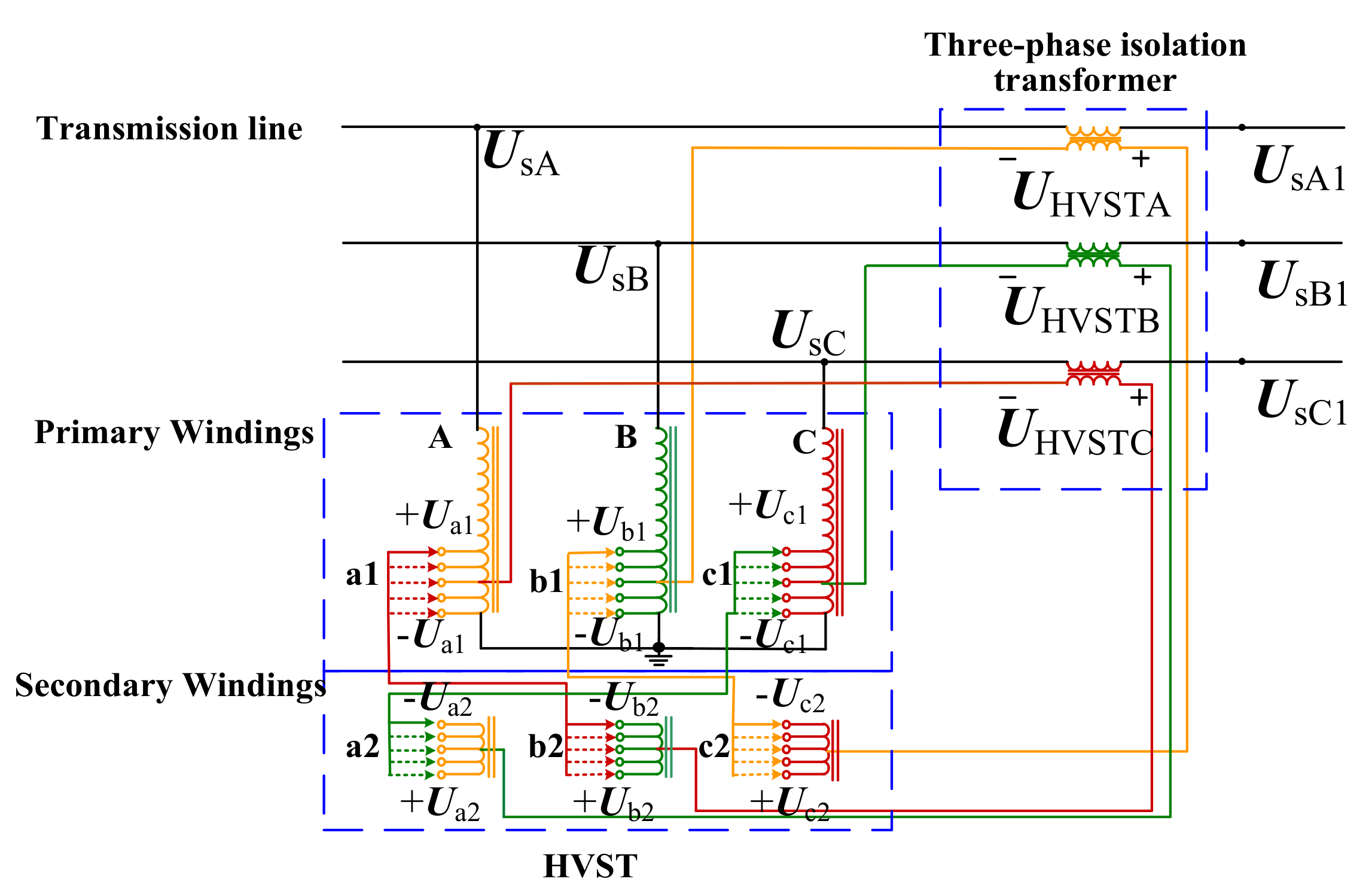
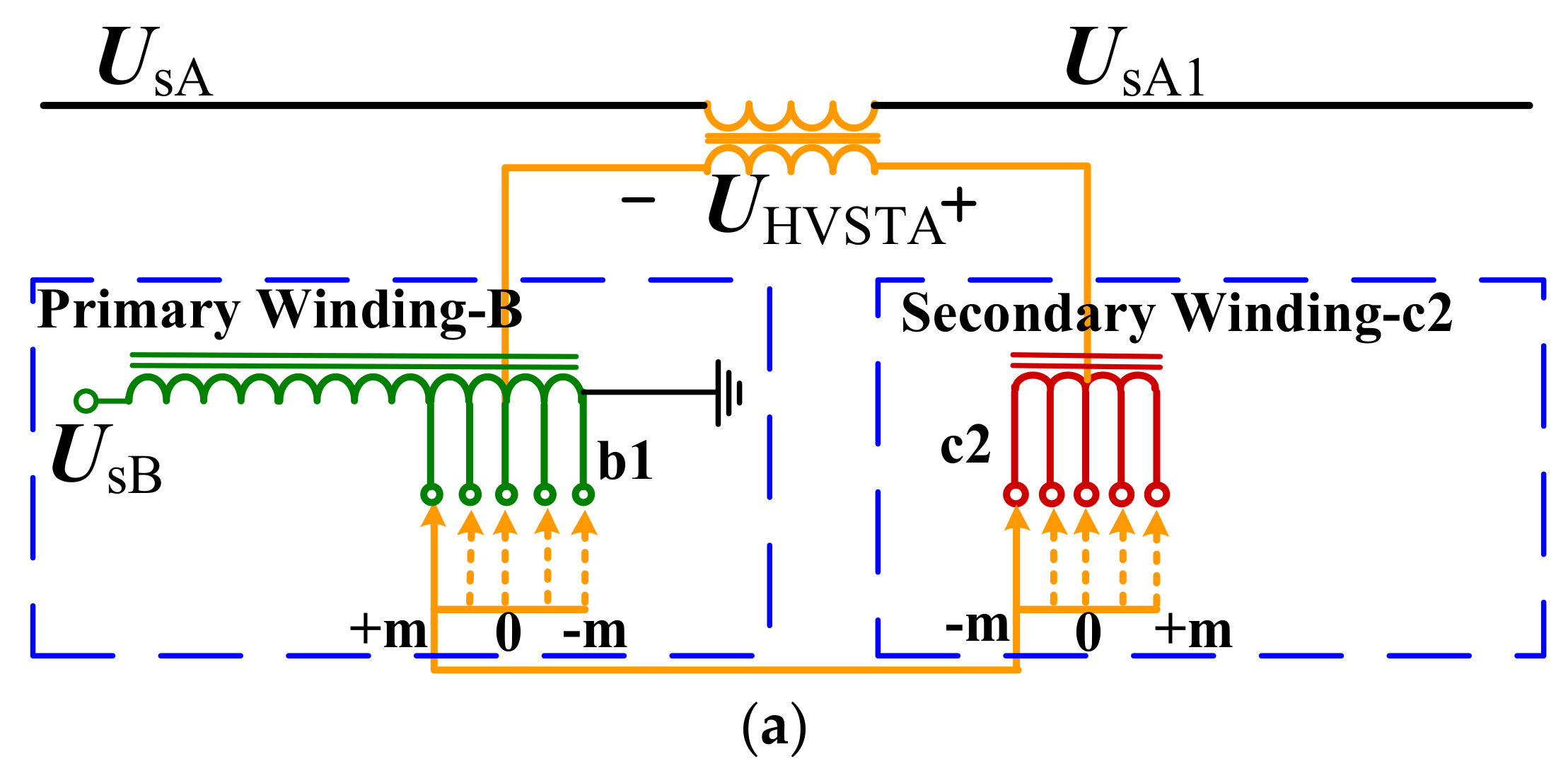
2.2. HVST Configuration
3. The Fundamental Principles of the HVST
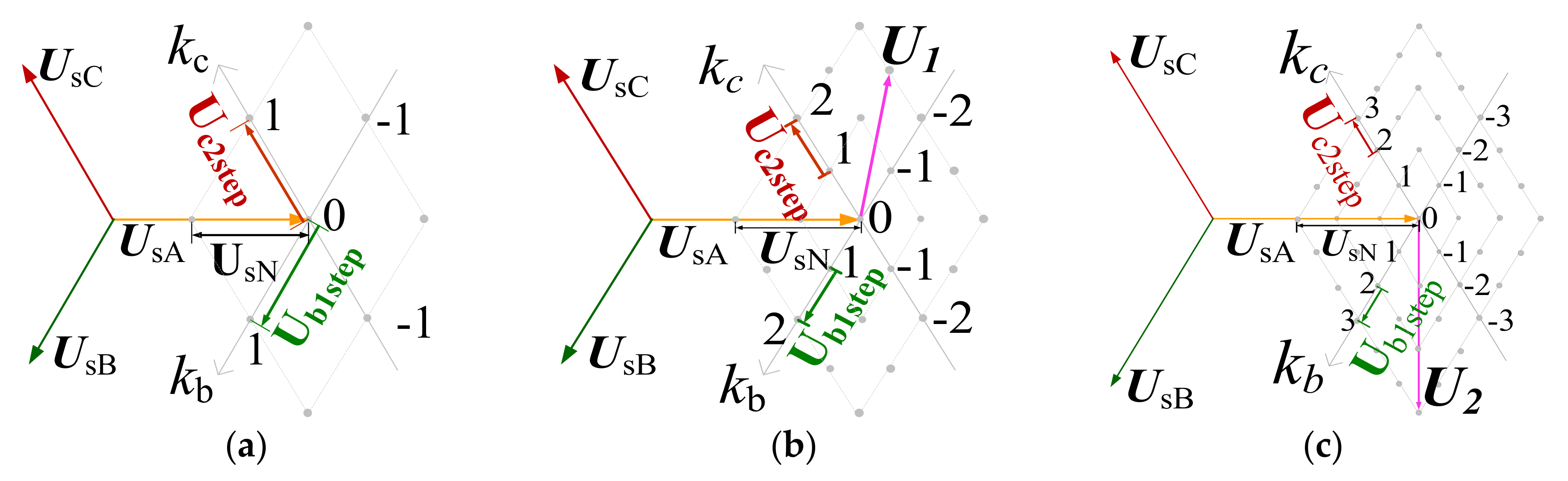
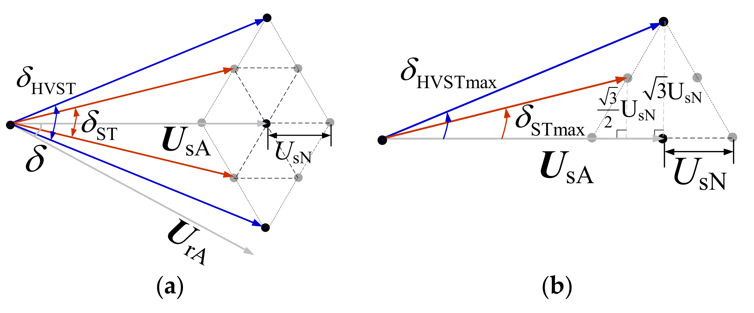
3.1. HVST Output Voltage Phasor
3.2. HVST Power Flow Control
4. Comparison between the ST and the HVST
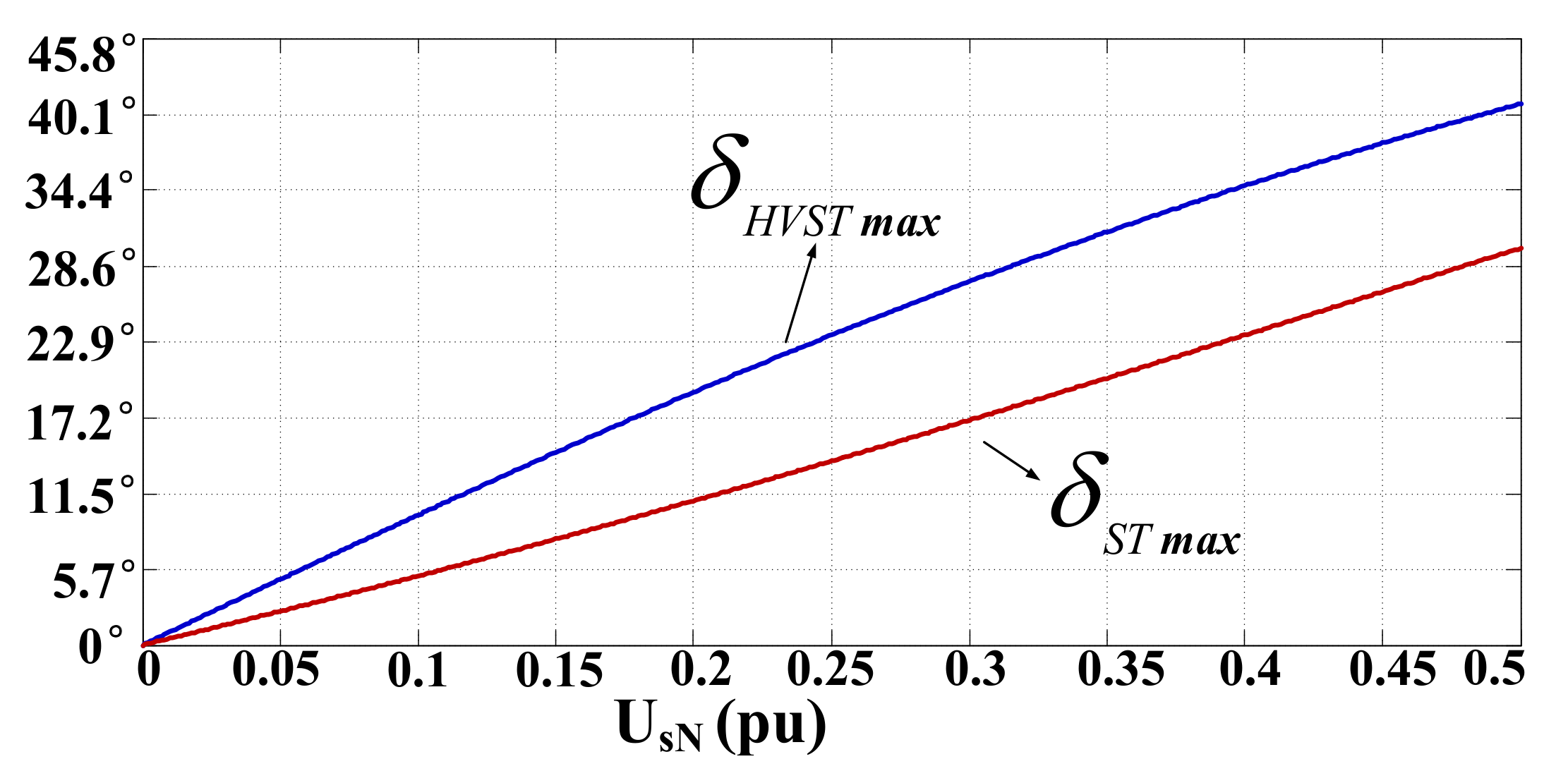
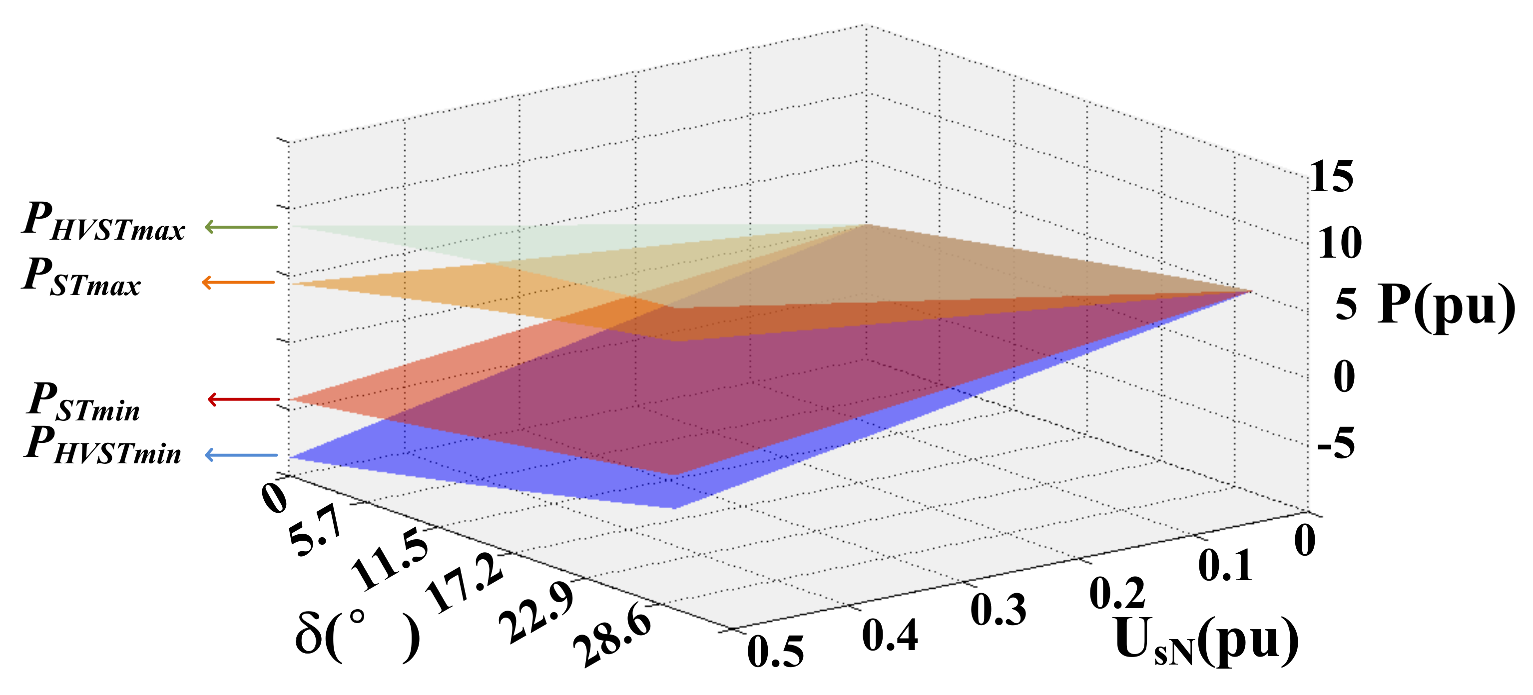
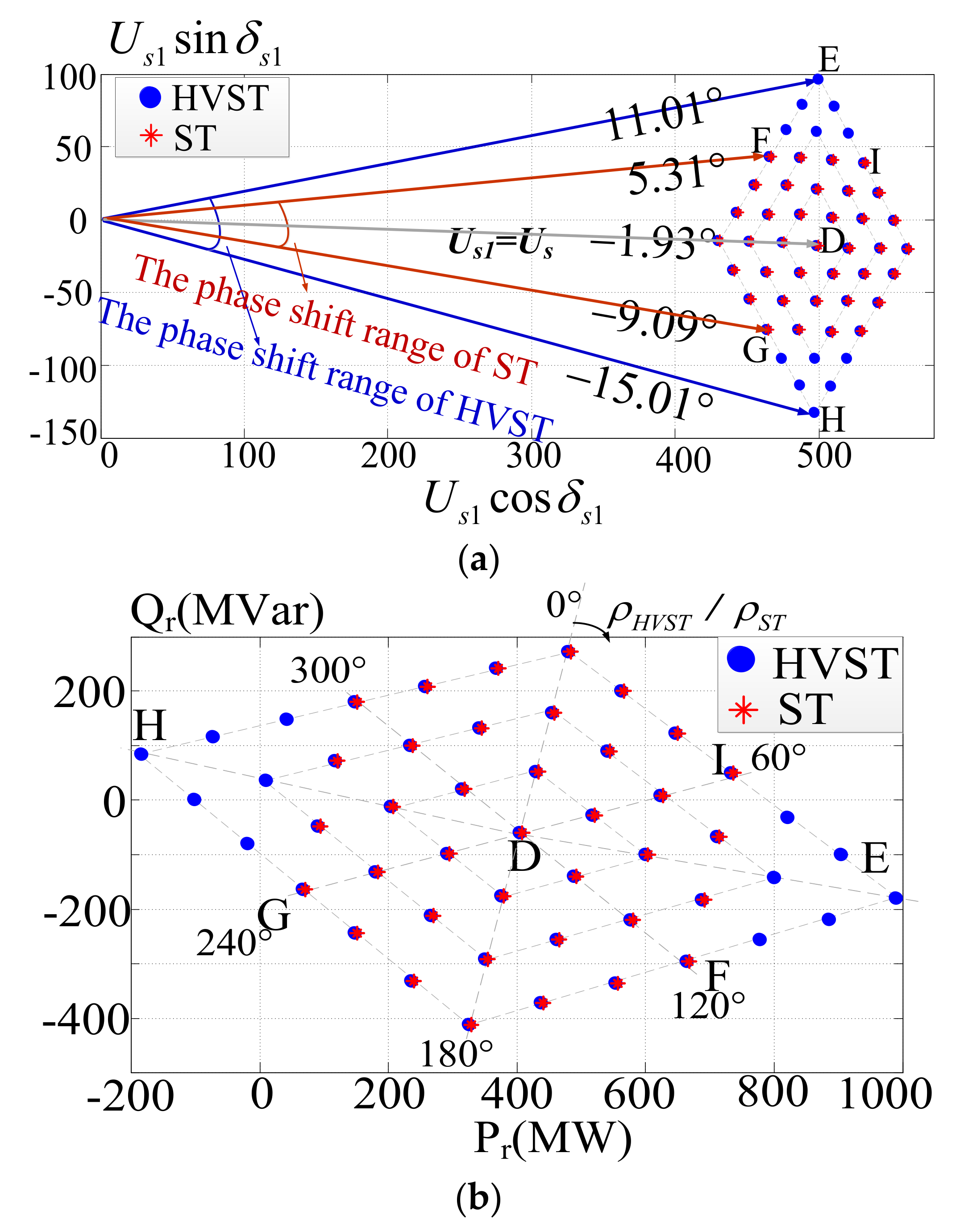
4.1. Phase-Shift Angle Range
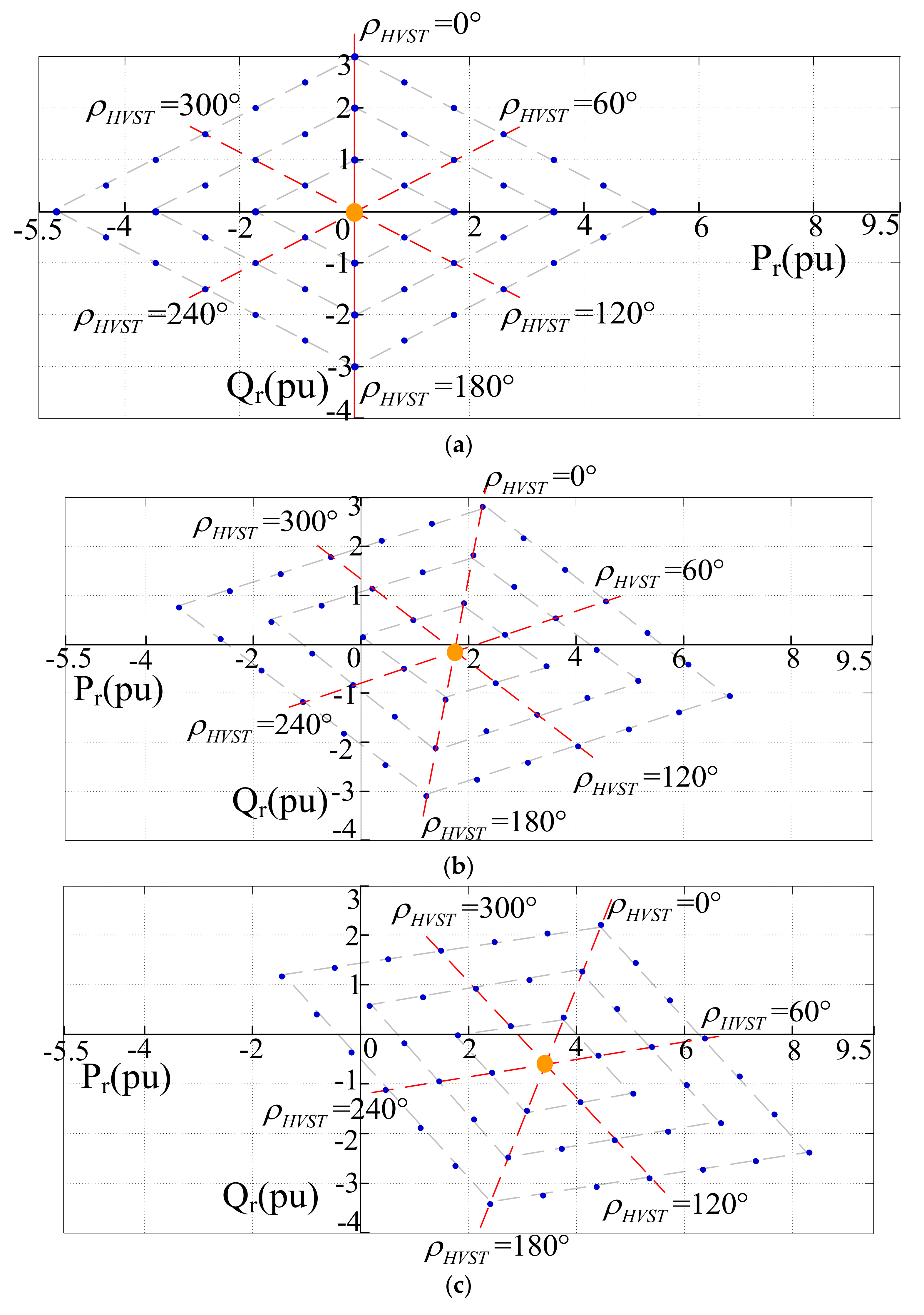
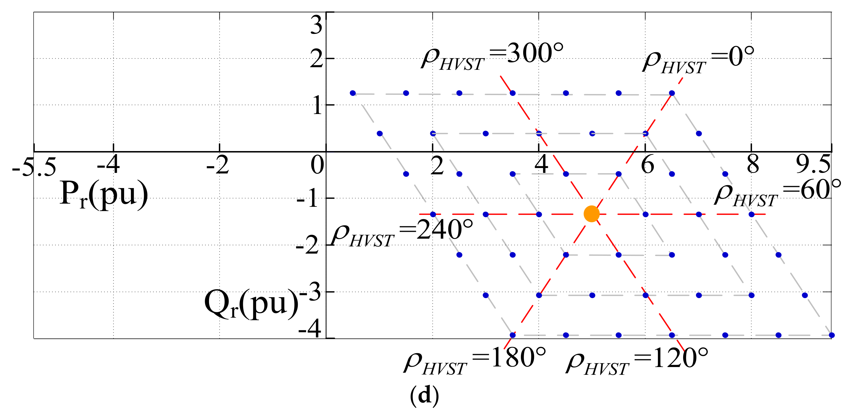
4.2. Power Flow Regulatory Region
4.3. Comprehensive Comparison Between the ST and the HVST
5. Simulation
5.1. Two-Area Test System
5.1.1. System Description
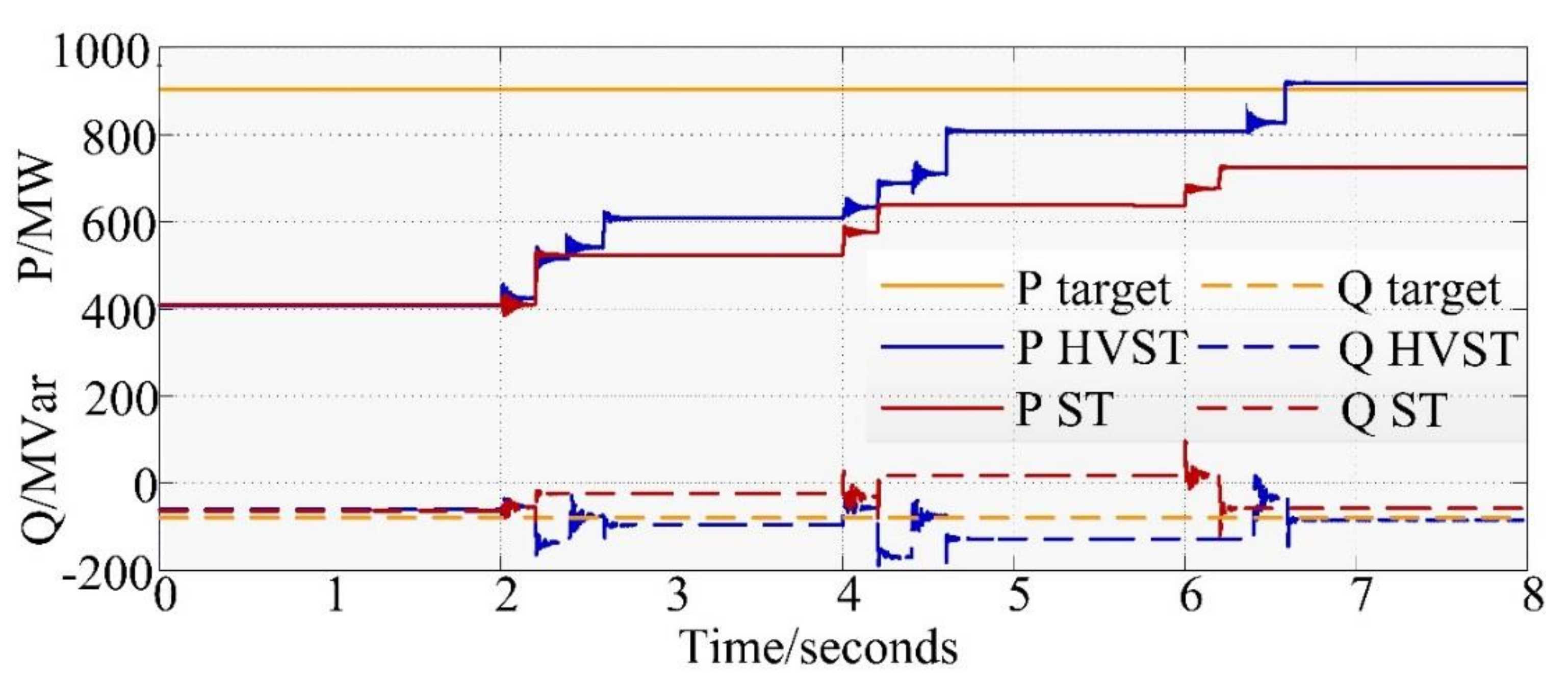
5.1.2. Simulation Results
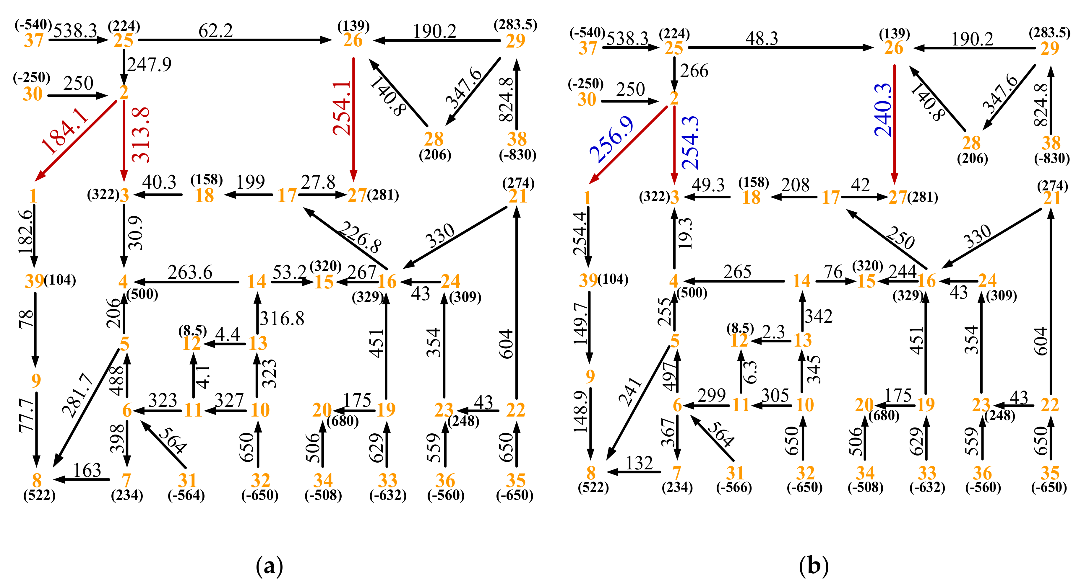
5.2. Application to an IEEE 39 Bus System
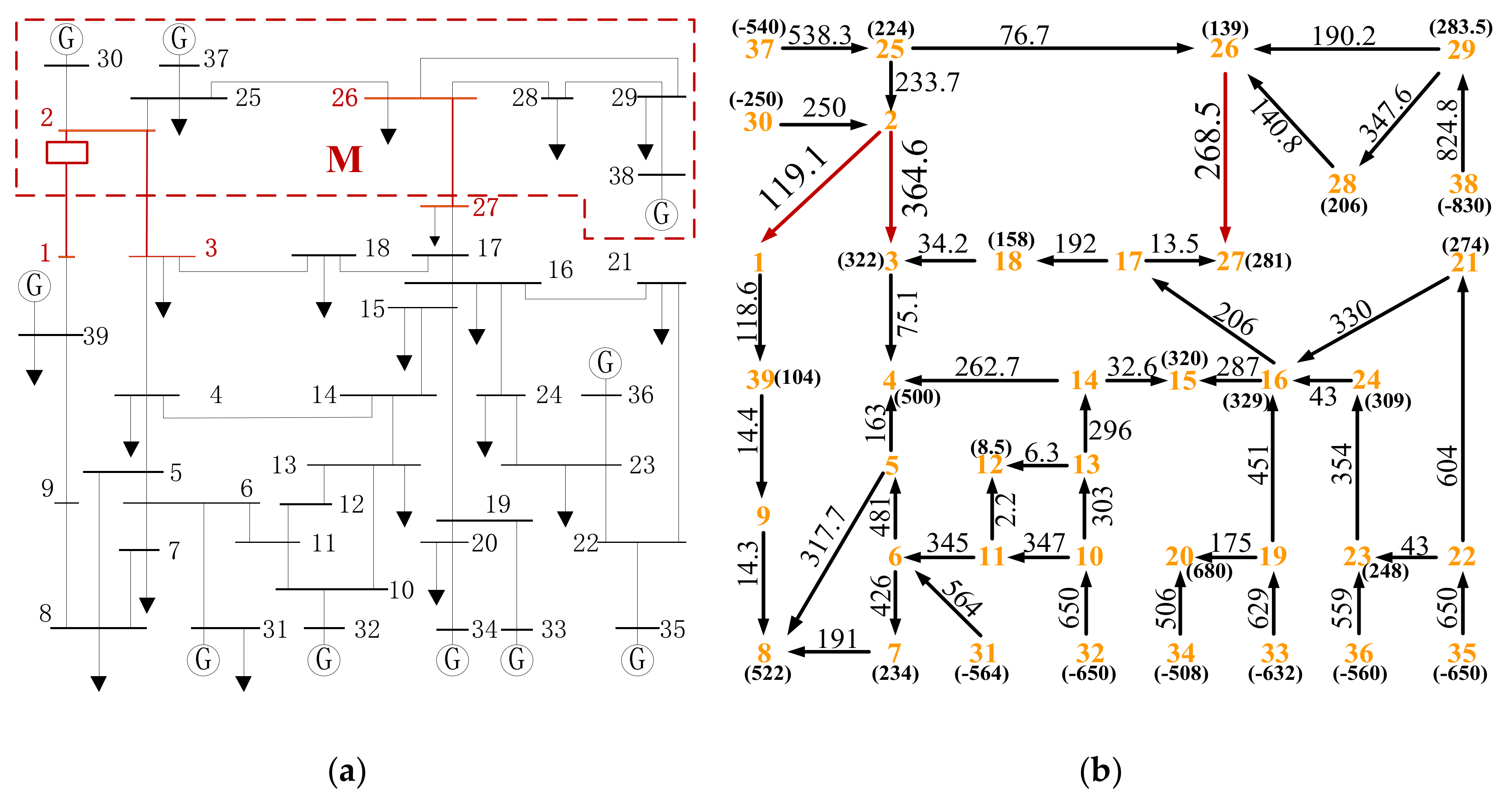
5.2.1. Network Model
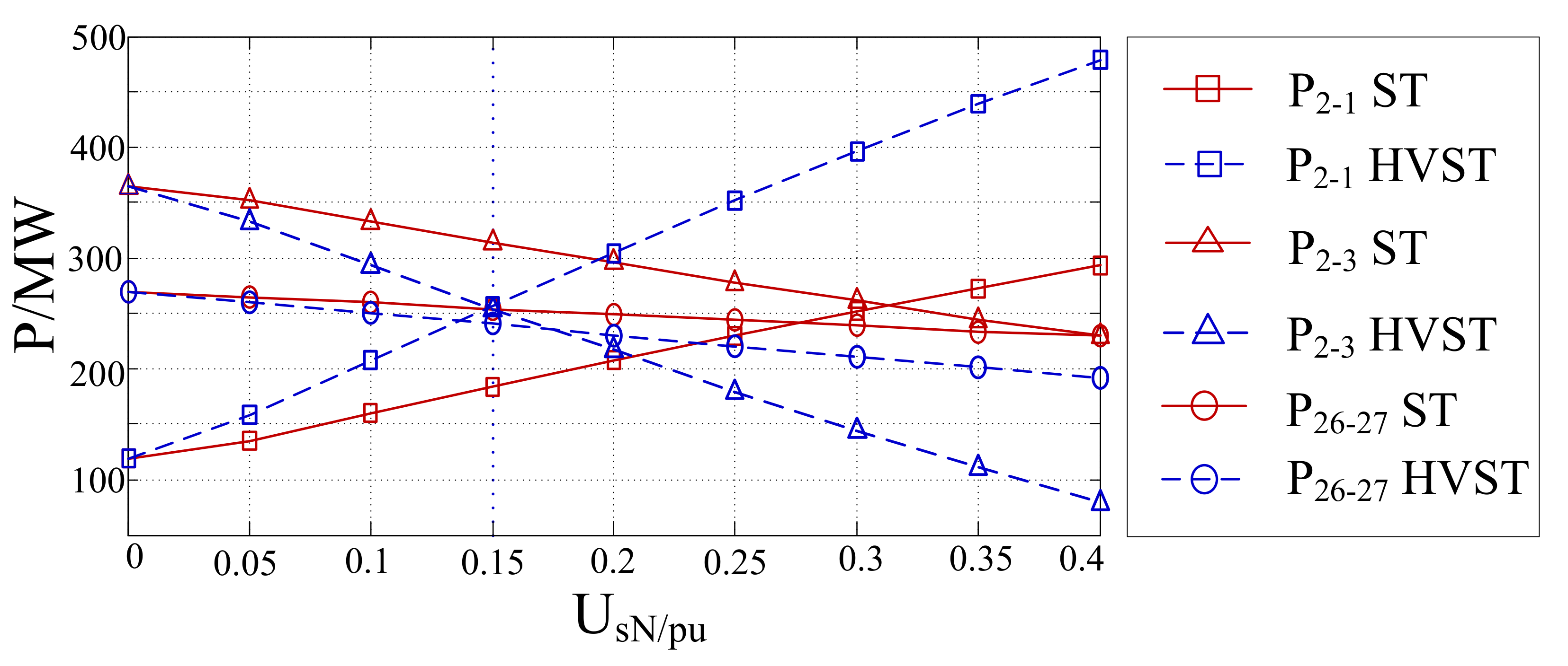
5.2.2. Simulation Results
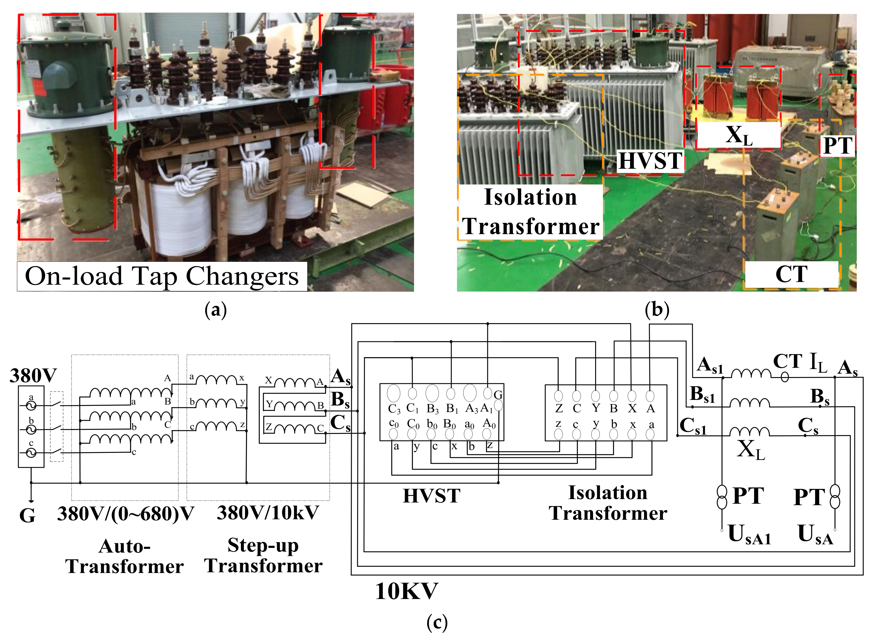
6. Experiment
6.1. Experimental Platform
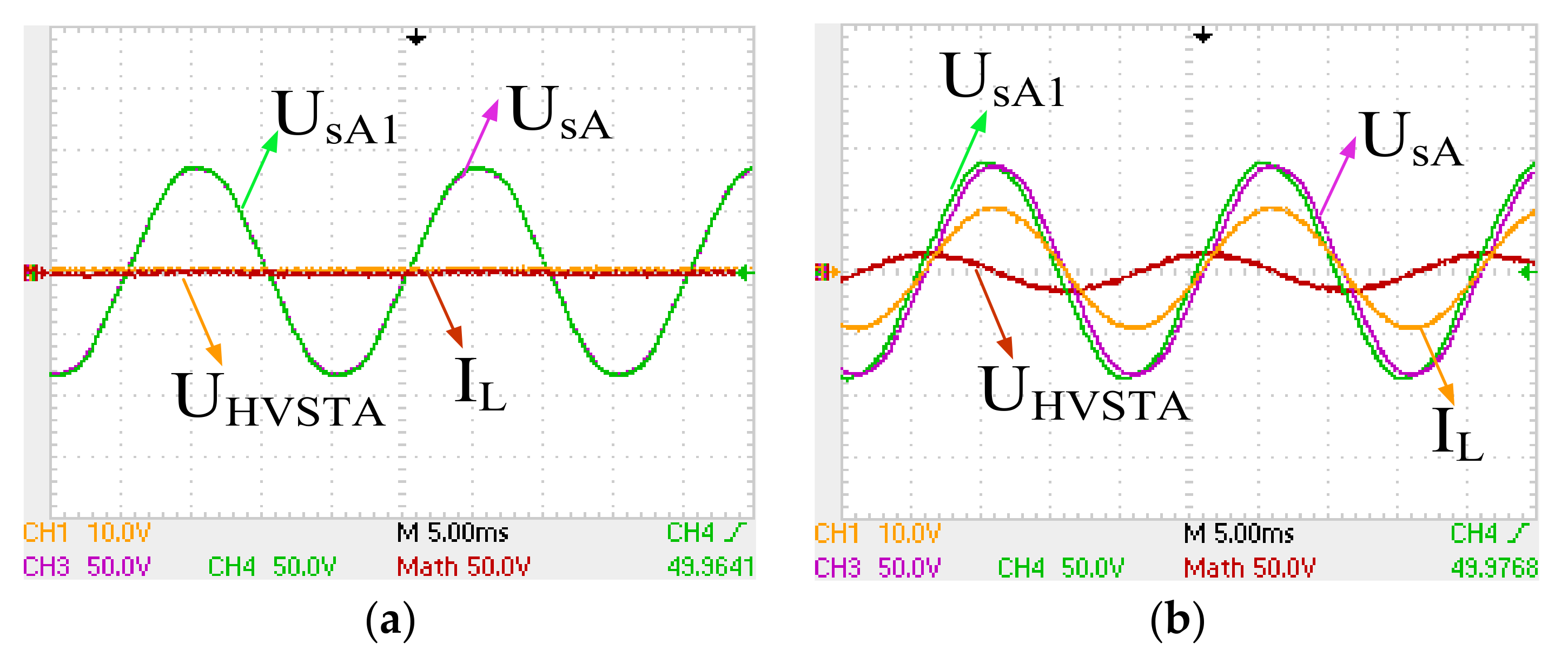
6.2. Experimental Results
7. Conclusions
Acknowledgments
Author Contributions
Conflicts of Interest
References
- Samorodov, G.; Kandakov, S.; Zilberman, S.; Krasilnikova, T.; Tavares, M.C.; Machado, C.; Li, Q. Technical and economic comparison between direct current and half-wavelength transmission systems for very long distances. IET Gener. Transm. Distrib. 2017, 11, 2871–2878. [Google Scholar] [CrossRef]
- Miao, J.; Zhang, N.; Kang, C.; Wang, J.; Wang, Y.; Xia, Q. Steady-state power flow model of energy router embedded AC network and its application in optimizing power system operation. IEEE Trans. Smart Grid 2017. [Google Scholar] [CrossRef]
- Choudekar, P.; Sinha, S.K.; Siddiqui, A. Transmission line efficiency improvement and congestion management under critical contingency condition by optimal placement of TCSC. In Proceedings of the India International Conference on Power Electronics, Patiala, India, 17–19 November 2016. [Google Scholar] [CrossRef]
- Gajbhiye, R.K.; Naik, D.; Dambhare, S.; Soman, S.A. An expert system approach for multi-year short-term transmission system expansion planning: An Indian experience. IEEE Trans. Power Syst. 2008, 23, 226–237. [Google Scholar] [CrossRef]
- Arevalo, F.; Cordova, M.; Quizhpi, F.; Vivar, M. Genetic algorithm for enhancing the transmission capacity of a PES (power electric system) through flexible AC compensators. In Proceedings of the IEEE Conference on Industrial Electronics and Applications, Hangzhou, China, 9–11 June 2014. [Google Scholar] [CrossRef]
- Hingorani, N.G.; Gyugyi, L. Understanding FACTS: Concepts and Technology of Flexible AC Transmission Systems, 1st ed.; IEEE: New York, NY, USA, 2000; pp. 1–35, 0-7803–3455-8. [Google Scholar]
- Hao, J.; Shi, L.B.; Chen, C. Optimising location of unified power flow controllers by means of improved evolutionary programming. IEE Proc. Gener. Transm. Distrib. 2004, 151, 705–712. [Google Scholar] [CrossRef]
- Song, P.E.; Xu, Z.; Dong, H. UPFC-based line overload control for power system security enhancement. IET Gener. Transm. Distrib. 2017, 11, 3310–3317. [Google Scholar] [CrossRef]
- Liu, Y.; Yang, S.; Wang, X.; Gunasekaran, D.; Karki, U.; Peng, F.Z. Application of transformer-less UPFC for interconnecting two synchronous AC grids with large phase difference. IEEE Trans. Power Electron. 2016, 31, 6092–6103. [Google Scholar] [CrossRef]
- Albatsh, F.M.; Mekhilef, S.; Ahmad, S.; Mokhlis, H. Fuzzy-logic-based UPFC and laboratory prototype validation for dynamic power flow control in transmission lines. IEEE Trans. Ind. Electron. 2017, 64, 9538–9548. [Google Scholar] [CrossRef]
- Zahid, M.; Chen, J.; Li, Y.; Duan, X.; Lei, Q.; Bo, W.; Mohy-ud-din, G.; Waqar, A. New Approach for Optimal Location and Parameters Setting of UPFC for Enhancing Power Systems Stability under Contingency Analysis. Energies 2017, 10, 1738. [Google Scholar] [CrossRef]
- Li, P.; Lin, J.; Kong, X.; Wang, Y. Application of MMC-UPFC and its performance analysis in Nanjing Western Grid. In Proceedings of the IEEE PES Asia-Pacific Power and Energy Engineering Conference, Xi’an, China, 25–28 October 2016. [Google Scholar] [CrossRef]
- Sen, K.K.; Sen, M.L. Introducing the family of “SEN” Transformer: A set of power flow controlling transformers. IEEE Trans. Power Deliv. 2003, 18, 148–157. [Google Scholar] [CrossRef]
- Sen, K.K.; Sen, M.L. Comparison of the “SEN” Transformer with the unified power flow controller. IEEE Trans. Power Deliv. 2003, 18, 1523–1533. [Google Scholar] [CrossRef]
- Faruque, M.O.; Dinavahi, V. A tap-changing algorithm for the implementation of “SEN” transformer. IEEE Trans. Power Deliv. 2007, 22, 1750–1757. [Google Scholar] [CrossRef]
- Mohamed, S.E.G.; Jasni, J.; Radzi, M.A.M.; Hizam, H.; Mirzaei, M. Optimal allocation of Sen transformer for active power loss reduction. In Proceedings of the IEEE International Conference on Power and Energy, Kuching, Malaysia, 1–3 December 2014. [Google Scholar] [CrossRef]
- Liu, J.; Dinavahi, V. Nonlinear magnetic equivalent circuit based real time Sen transformer electromagnetic transient model on FPGA for HIL emulation. IEEE Trans. Power Deliv. 2016, 31, 2483–2493. [Google Scholar] [CrossRef]
- Yuan, J.; Chen, L.; Chen, B.C. The improved Sen transformer—A new effective approach to power transmission control. In Proceedings of the IEEE Energy Conversion Congress and Exposition, Pittsburgh, PA, USA, 14–18 September 2014. [Google Scholar] [CrossRef]
- Yuan, J.; Liu, L.; Fei, W.; Chen, L.; Chen, B.C.; Chen, B. Hybrid electromagnetic unified power flow controller: A novel flexible and effective approach to control power flow. IEEE Trans. Power Deliv. 2017. [Google Scholar] [CrossRef]
- Sen, K.K.; Sen, M.L. Unique capabilities of Sen transformer: A power flow regulating transformer. In Proceedings of the IEEE Power and Energy Society General Meeting, Boston, MA, USA, 17–21 July 2016. [Google Scholar] [CrossRef]


| Item | ST | HVST |
|---|---|---|
| Phase-shift angle range | small | large |
| Power flow regulatory region | small | large |
| Number of secondary windings | 9 | 3 |
| Number of tap changers | 3 | 2 |
| Number of isolated transformers (Us < 230 kV) | 0 | 1 |
| Number of isolated transformers (Us ≥ 230 kV) | 1 | 1 |
| Parameters | Value |
|---|---|
| Base values | 500 kV |
| Frequency | 50 Hz |
| Sending-end line-to-line voltage | 500∠0° kV |
| Receiving-end line-to-line voltage | 500∠−10° kV |
| Source impedance at the sending end | 1.05 + j10.5 Ω |
| Source impedance at the receiving end | 1.05 + j10.5 Ω |
| Transmission line impedance | 6.24 + j84.63 Ω |
| Rated voltage of the HVST | 75 kV |
| Tap positions of the HVST | 0, ±1, ±2, ±3 |
| Rated voltage of the ST | 75 kV |
| Tap positions of the ST | 0, 1, 2, 3 |
| Point | Item | UHVST, UST (kV) | Us1 (kV) | δHVST, δST | Pr (MW) | Qr (MVar) |
|---|---|---|---|---|---|---|
| D | ST | 0 | 499∠−1.9° | 0° | 405 | −61 |
| HVST | 0 | 499∠−1.9° | 0° | 405 | −61 | |
| E | ST | — | — | — | — | — |
| HVST | 126∠87° | 510∠11° | 12.9° | 990 | −176 | |
| F | ST | 74.0∠118° | 468∠5.4° | 7.3° | 666 | −296 |
| HVST | 74.5∠118° | 468∠5.3° | 7.2° | 667 | −297 | |
| G | ST | 75∠−121° | 471∠−9.1° | −7.2° | 66 | −163 |
| HVST | 75∠−121° | 470∠−9.1° | −7.2° | 64 | −164 | |
| H | ST | — | — | — | — | — |
| HVST | 129∠−91° | 514∠−15° | −13.1° | −188 | 85 | |
| I | ST | 73.4∠57° | 534∠4.1° | 6.0° | 734.3 | 48.3 |
| HVST | 72.7∠57° | 534∠4.1° | 6.0° | 732.8 | 47.6 |
| Parameters | ST-1 | ST-2 | HVST |
|---|---|---|---|
| Base values | 330 kV | 330 kV | 330 kV |
| Rated voltage(UsN) | 0.15 pu | 0.3 pu | 0.15 pu |
| Primary winding voltage | 1 pu | 1 pu | 1 pu |
| Secondary winding voltage | 0.15 pu × 3 | 0.3 pu × 3 | 0.15 pu × 2 |
| Number of tap changers | 3 | 3 | 2 |
| Number of isolated transformers | 1 | 1 | 1 |
| Unbalance of active power flows on the three lines | 70% | 9% | 7% |
| Parameters | Value |
|---|---|
| Base values | 10 kV |
| Frequency | 50 Hz |
| Sending-end line-to-line voltage | 1.04∠0° pu |
| Receiving-end line-to-line voltage | 1.04∠0° pu |
| Transmission line impedance XL | 0.713 H |
| Rated voltage of the HVST transformer | 0.2 pu |
| Tap position of the HVST transformer | 0, ±1, ±2, ±3, ±4 |
© 2018 by the authors. Licensee MDPI, Basel, Switzerland. This article is an open access article distributed under the terms and conditions of the Creative Commons Attribution (CC BY) license (http://creativecommons.org/licenses/by/4.0/).
Share and Cite
Chen, B.; Fei, W.; Tian, C.; Yang, L.; Gu, J. A High-Voltage “Sen” Transformer: Configuration, Principles, and Applications. Energies 2018, 11, 918. https://doi.org/10.3390/en11040918
Chen B, Fei W, Tian C, Yang L, Gu J. A High-Voltage “Sen” Transformer: Configuration, Principles, and Applications. Energies. 2018; 11(4):918. https://doi.org/10.3390/en11040918
Chicago/Turabian StyleChen, Baichao, Wenli Fei, Cuihua Tian, Lingang Yang, and Jianwei Gu. 2018. "A High-Voltage “Sen” Transformer: Configuration, Principles, and Applications" Energies 11, no. 4: 918. https://doi.org/10.3390/en11040918
APA StyleChen, B., Fei, W., Tian, C., Yang, L., & Gu, J. (2018). A High-Voltage “Sen” Transformer: Configuration, Principles, and Applications. Energies, 11(4), 918. https://doi.org/10.3390/en11040918