Power System Restoration Planning Strategy Based on Optimal Energizing Time of Sectionalizing Islands

 ,
,
Abstract
:1. Introduction
2. Power System Restoration Formulation
2.1. Objective Function
2.2. Constraints
- BS unit availability at each island.where: is a set of buses in each ‘r’ island created, b is the bus number and ∂ is the total number of islands. A subset is defined to represent generators which are BS units in set of total buses in a system. Each island must have at least one BS generator.
- Load-generation balance.where: In each ‘r’ island, the total maximum active power generation must be higher than the total load in order to avoid frequency drop and subsequent system collapse. In this paper, reactive power balance is not considered. However, the balance of reactive power is indirectly taken into account thorough the voltage profile constraint as per Equation (4). This is due to the strong dependence of voltage magnitude on reactive power.
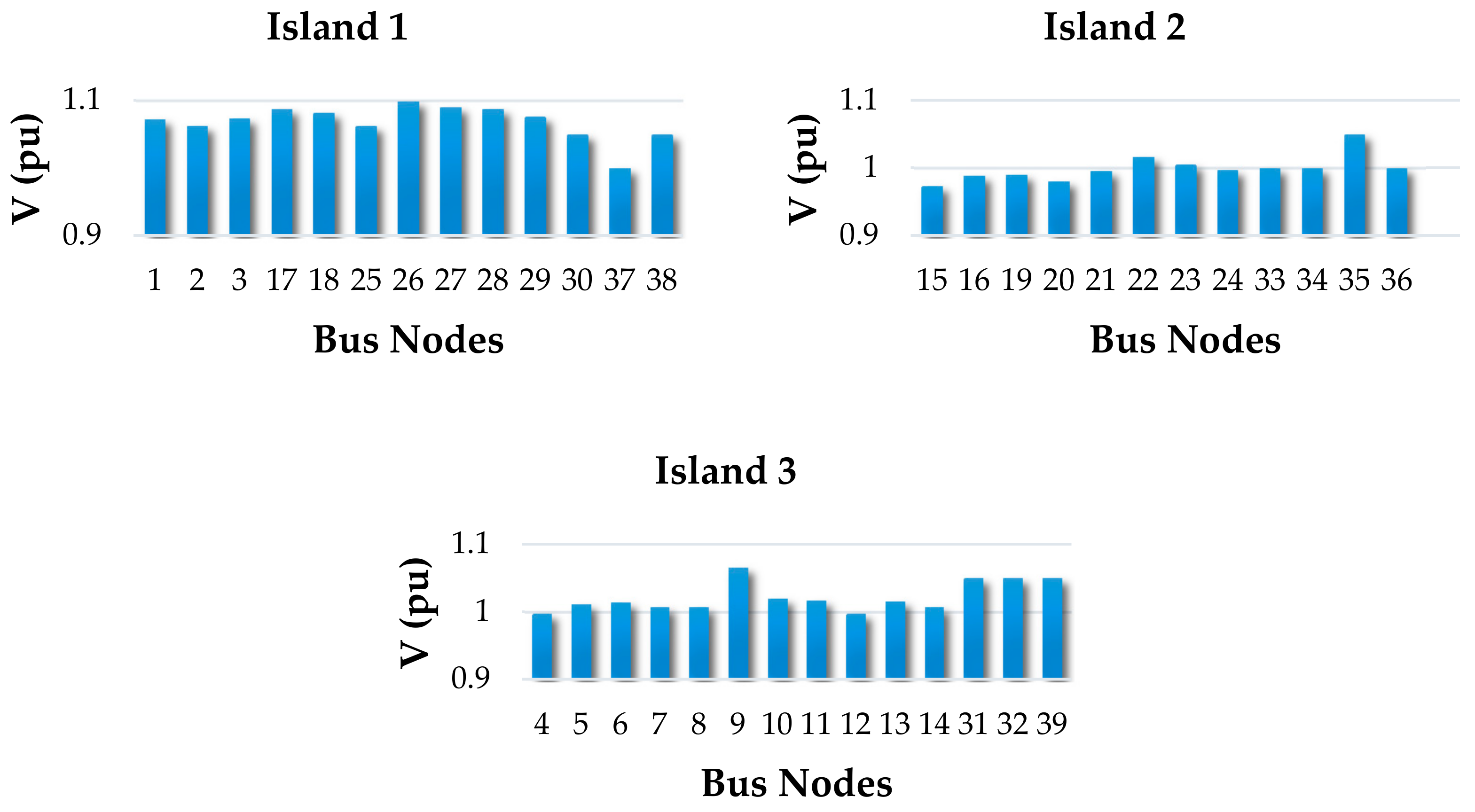
- To maintain an acceptable steady state voltage profile.where: Each bus voltage in each ‘r’ island is within the acceptable voltage range in ±5–10% of the rated voltage. Violating the boundaries of the nominal voltage will cause voltage instability, which might affect the system.
3. Power System Restoration Planning
3.1. Network Modelling via Graph Theory
Determination of the Shortest Energizing Path
3.2. Heuristic Technique
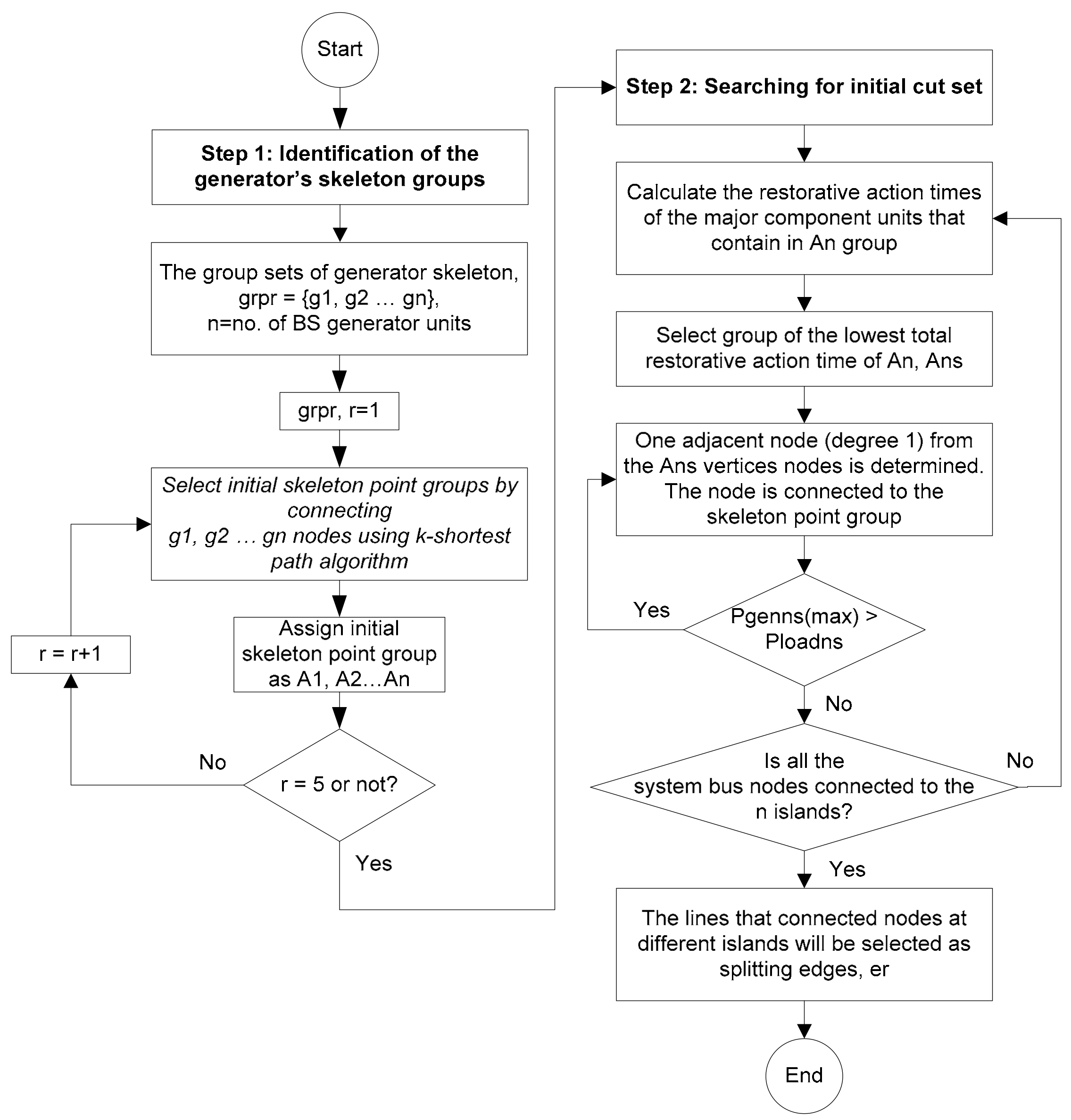
3.2.1. Step 1: Identification of the Generator’s Skeleton Groups
- The k-shortest path method is used to list all possible sets of generator’s groups, grpσ = {g1, g2 … gσ}, where ‘σ’ represents the possible set number of different generator groups, while ‘r’ represents the number of generator groups for each set by referring to the number of BS generators. Each set needs to fulfill the following requirements (i) the skeletons of each group do not overlap with each other, and (ii) each group must have at least one BS generator unit.
- In each set of the generator groups, the total power generation and their skeleton size are determined. The total power generation for ‘r’ generator group = {PG1, PG2 … PGr}, while the skeleton size is the number of edges covering the path between generator units in a group, s = {s1, s2 … sr}. The total power generation balance (∆PG) and the gap of the skeleton size (∆s) are calculated using Equations (6) and (7), respectively.
- 3.
- Rank the sets according to the lowest active power generation balance between the groups and the smallest gap size of the skeletons. This criterion is chosen to obtain a good initial starting point to create islands with similar energizing time. In this work, five possible sets of generator groups are selected as initial solutions.
- 4.
- Each set of generator group’s initial skeleton point is determined by connecting the generator groups, g1, g2 … gr nodes using the k-shortest path algorithm. Assign the initial skeleton point as {A1, A2 … Ar}.
3.2.2. Step 2: Searching for the Initial Cut Set
- Expanding the island step from the initial skeleton point is done by considering the restorative time of generators, loads, buses and lines. The time taken to re-energize major power system units is as follows: (1) Restart BS unit, 15 min; (2) Energise a bus from BS unit, 5 min; (3) Connect tie line, 25 min; (4) Crank power to a NBS unit from a bus, 15 min; (5) Synchronized subsystems, 25 min; (6) Pick up load, 20 min [9,21]. The group with the lowest restoration times is chosen and assigned as Ans.
- Adjacent node with a degree of 1 from Ars nodes is determined. The nodes are connected one by one to the skeleton group while checking their load-generation balance shown in Equation (8). The connection process is continued until the total load is greater than the maximum active power generation.rs = island with lowest energizing time.
- The steps in 1 & 2 are repeated until all nodes in the system are connected to r islands.
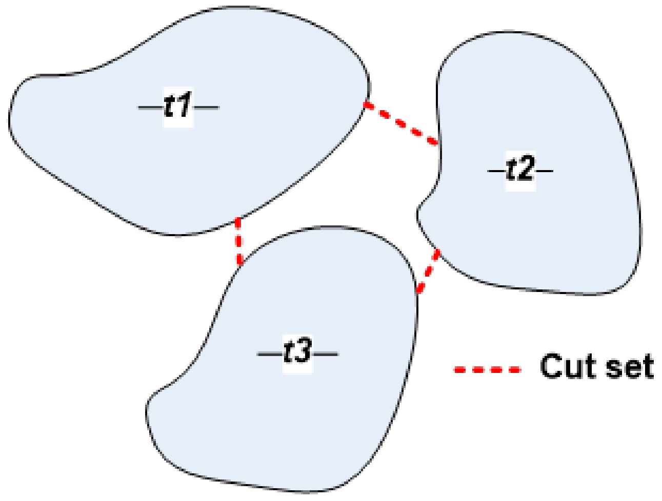
- The lines that connect the nodes at different islands will be selected as the cut set.
3.3. Discrete ABC Method
4. Power Energizing Time Calculation
- Graph theory is used to model the power system using the bus and line data. Both data are required to assign the nodes, edges, and weights in the graph. The cut set is determined using the proposed restoration strategy to create the desired number of islands. Each island calculates the energizing time in parallel.
- The energizing time algorithm uses the k-shortest method assisted by graph theory to search the shortest path to reenergize the backbone, starting with the BS unit. The time taken to energize the searched units is calculated. The first reenergizing approach will stop at this step.
- The second approach continues to search and calculate the energizing time for the rest of the major power system units. This step is repeated until all units in the island are restored.
5. Simulation Results
5.1. IEEE 39-Bus Test System
- (a)
- Maximum active power generation balance
- (b)
- Gap of the skeleton size.
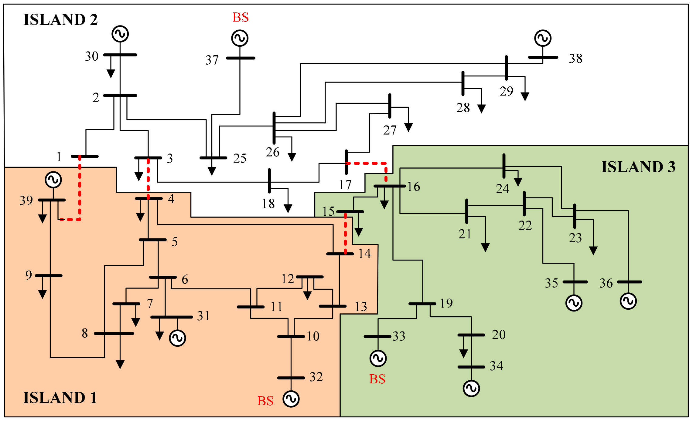
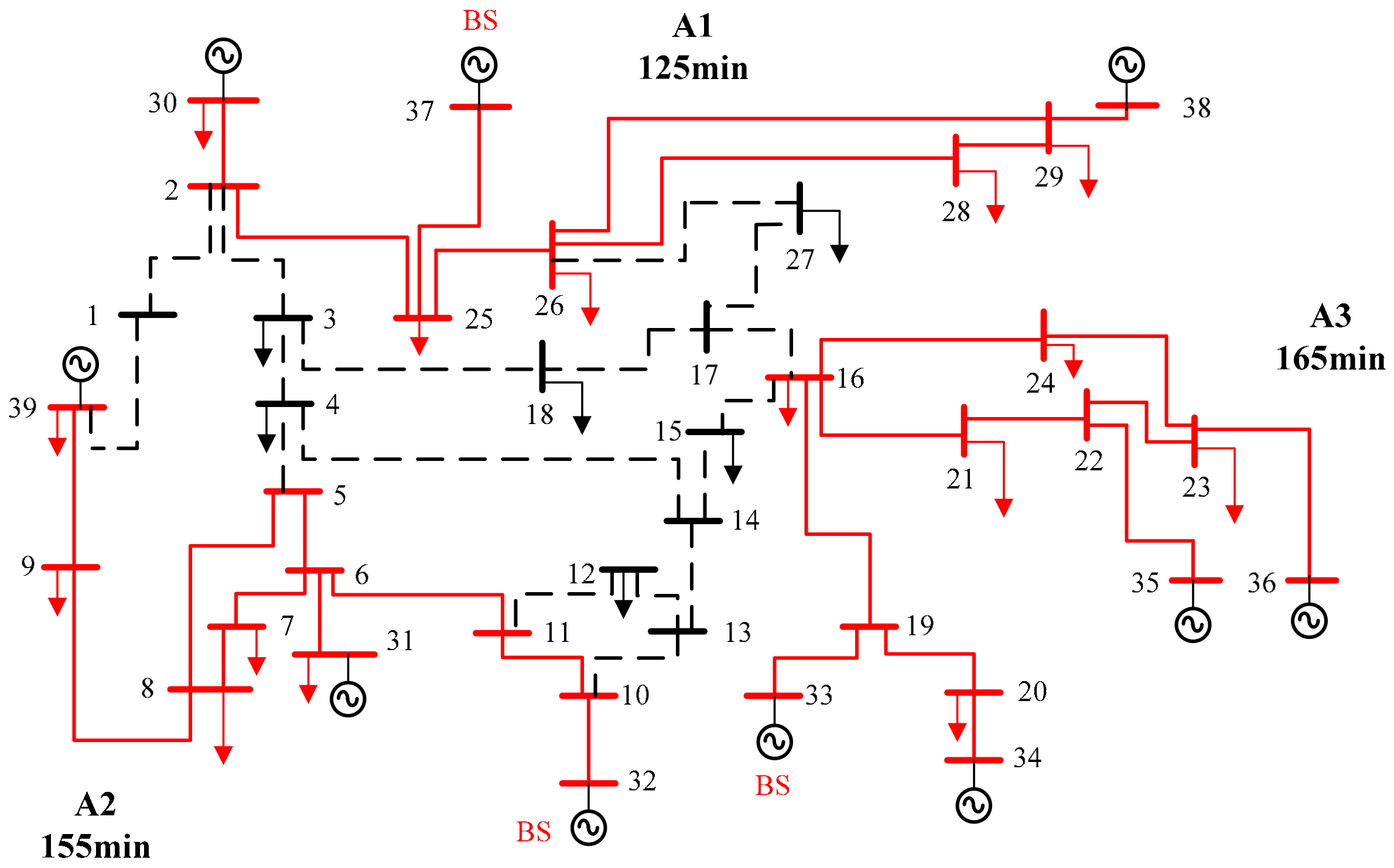
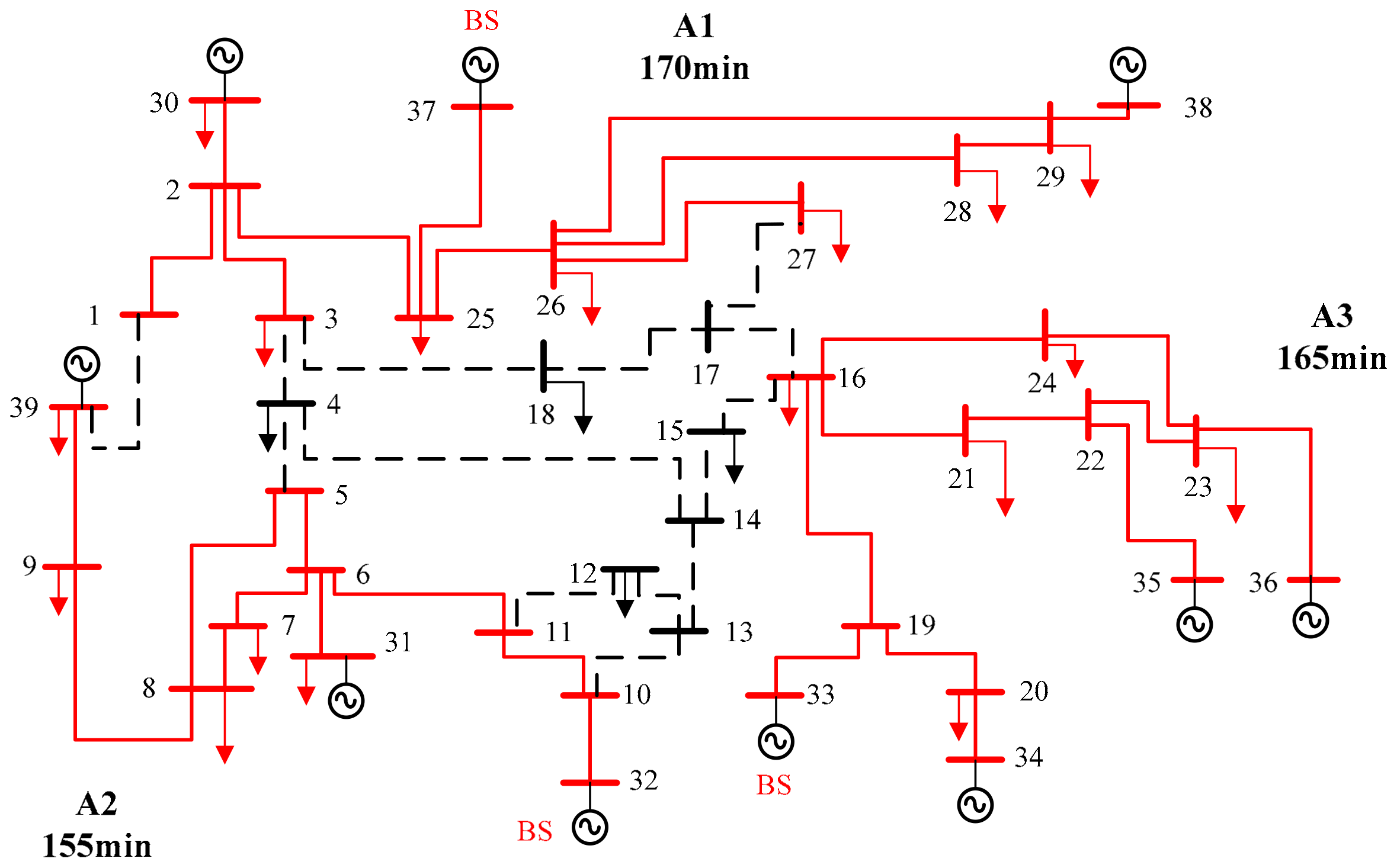
- Figure 4 shows the generator skeleton for group A1, A2, and A3 groups. The buses that connect the generator units are set in the same skeleton group. The load-generation power balance and restorative time of individual power units for each skeleton group are determined. The group that has the lowest restorative time is selected to expand the search for adjacent buses. Comparing the 3 groups, A1 has the lowest energizing time, which is 125 min, while A2 and A3 are 155 min and 165 min, respectively. Thus, A1 is selected first.
- The search step is carried out by determining the buses that are adjacent to buses in group A1 with one degree of connection. Nodes 1, 3, and 27 are selected and connected to A1, as shown in Figure 5. The energizing time for A1 becomes 170 min.
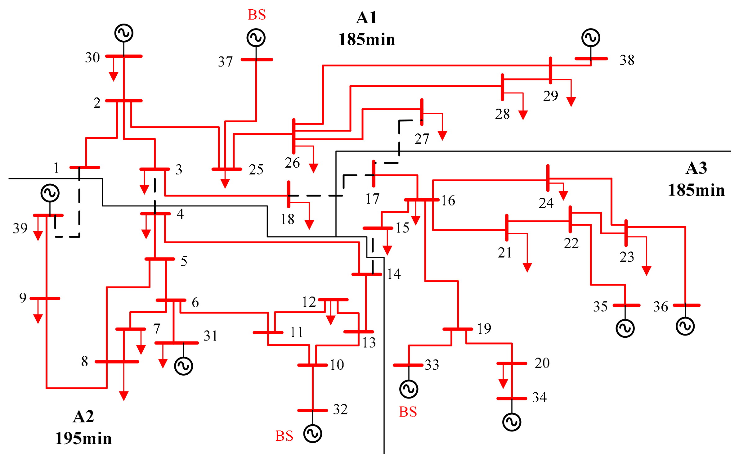
- The process is iterated until all buses are selected and included in their respective groups. The final result of group set 1 and the resultant initial cut set is shown in Figure 6.
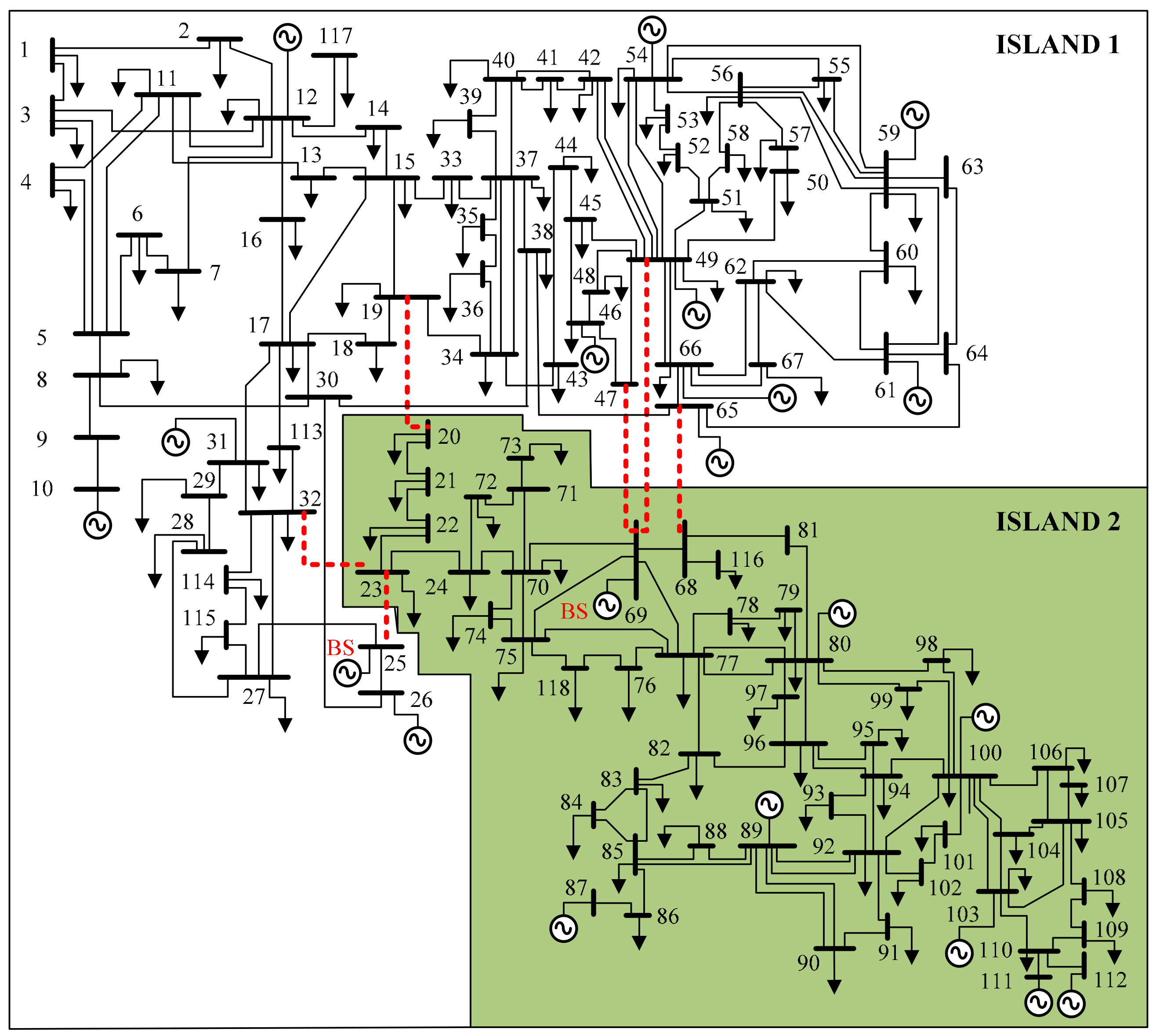
5.2. IEEE 118-Bus Test System
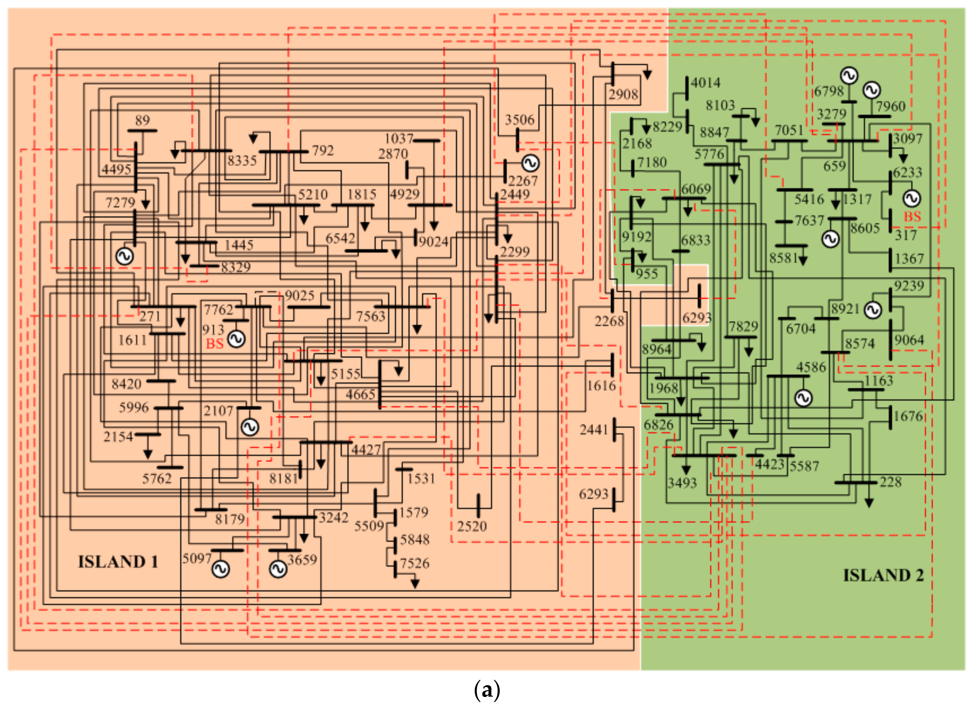
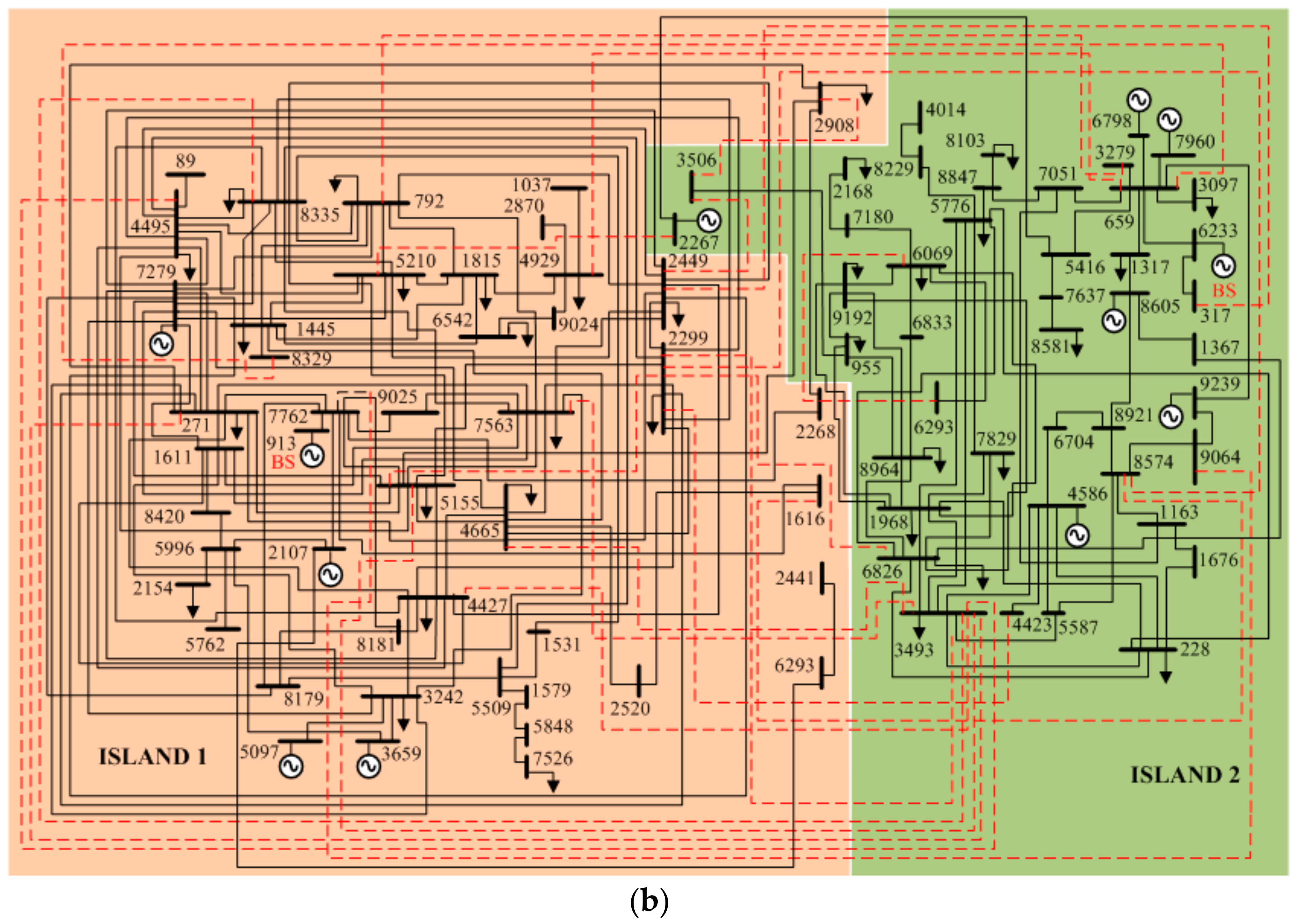
5.3. 89 Bus European Transmission System
6. Discussion and Future Work
7. Conclusions
Author Contributions
Acknowledgments
Conflicts of Interest
References
- Corsi, S.; Sabelli, C. General blackout in Italy Sunday September 28, 2003, h. 03:28:00. In Proceedings of the IEEE Power Engineering Society General Meeting, Denver, CO, USA, 6–10 June 2004; pp. 1691–1702. [Google Scholar]
- Shuran, L.; Hui, D.; Su, G. Analyses and discussions of the blackout in Indian power grid. Energy Sci. Technol. 2003, 6, 61–66. [Google Scholar]
- Massive Power Failure Plunges 80% of Pakistan into Darkness. Available online: https://www.theguardian.com/world/2015/jan/25/massive-power-failure-plunges-80-of-pakistan-into-darkness (accessed on 13 March 2018).
- Report on Blackout in Turkey on 31st March 2015. Available online: https://www.entsoe.eu/Documents/SOC%20documents/Regional_Groups_Continental_Europe/20150921_Black_Out_Report_v10_w.pdf (accessed on 13 March 2018).
- Adibi, M.M.; Clelland, P.; Fink, L.; Happ, H. Power system restoration—A task force report. IEEE Trans. Power Syst. 1987, 2, 271–277. [Google Scholar] [CrossRef]
- Adibi, M.M.; Fink, L.H. Power system restoration planning. IEEE Trans. Power Syst. 1994, 9, 22–28. [Google Scholar] [CrossRef]
- Quiros-Tortos, J.; Terzija, V. A smart power system restoration based on the merger of two different strategies. In Proceedings of the IEEE PES Innovative Smart Grid Technology (ISGT) Europe, Berlin, Germany, 14–17 October 2012; pp. 1–8. [Google Scholar]
- Liang, H.P. Subsystem partitioning for power system black-start considering restoration reliability. Tehnicki Vjesnik/Tech. Gaz. 2015, 22, 637. [Google Scholar] [CrossRef]
- Quiros-Tortos, J.; Terzija, V. A graph theory based new approach for power system restoration. In Proceedings of the IEEE Power Technology, Grenoble, France, 16–20 June 2013; pp. 1–6. [Google Scholar]
- The Grid Code; National Grid Electricity Transmission: London, UK, 2013.
- Gutierrez, J.; Staropolsky, M.; Garcia, A. Policies for restoration of a power system. IEEE Trans. Power Syst. 1987, 2, 436–442. [Google Scholar] [CrossRef]
- PJM Manual 36: System Restoration; PJM: Valley Forge, PA, USA, 2013.
- Quiros-Tortos, J.; Panteli, M.; Wall, P.; Terzija, V. Sectionalizing methodology for parallel system restoration based on graph theory. IET Gener. Transm. Distrib. 2015, 9, 1216–1225. [Google Scholar] [CrossRef]
- Quiros-Tortos, J.; Wall, P.; Ding, L.; Terzija, V. Determination of sectionalizing strategies for parallel power system restoration: A spectral clustering-based methodology. Electr. Power Syst. Res. 2014, 116, 381–390. [Google Scholar] [CrossRef]
- Afrakhteh, H.; Haghifam, M.R. Optimal islands determination in power system restoration. Iran. J. Sci. Technol. 2009, 33, 1–8. [Google Scholar]
- El-Zonkoly, A.M. Renewable energy sources for complete optimal power system black-start restoration. IET Gener. Transm. Distrib. 2015, 9, 531–539. [Google Scholar] [CrossRef]
- Nagata, T.; Sasaki, H. A multi-agent approach to power system restoration. IEEE Trans. Power Syst. 2002, 17. [Google Scholar] [CrossRef]
- Morelato, A.L.; Monticelli, A. Heuristic search approach to distribution system restoration. IEEE Trans. Power Deliv. 1989, 4. [Google Scholar] [CrossRef]
- Liu, Y.; Gu, X. Skeleton-network reconfiguration based on topological characteristics of scale-free networks and discrete particle swarm optimization. IEEE Trans. Power Syst. 2010, 22, 1267–1274. [Google Scholar] [CrossRef]
- Skiena, S. Dijkstra’s Algorithm, Implementing Discrete Mathematics: Combinatorics and Graph Theory with Mathematica Reading; Addison-Wesley: Boston, MA, USA, 1990; pp. 225–227. [Google Scholar]
- Sun, W.; Liu, C.C.; Zhang, L. Optimal generator start-up strategy for bulk power system restoration. IEEE Trans. Power Syst. 2011, 26, 1357–1366. [Google Scholar] [CrossRef]
- Karaboga, D.; Basturk, B. On the performance of artificial bee colony (ABC) algorithm. Appl. Soft Comput. 2008, 8, 687–697. [Google Scholar] [CrossRef]
- Karaboga, D.; Gorkemli, B.; Ozturk, C.; Karboga, N. A comparative survey: Artificial bee colony (ABC) algorithm and applications. Artif. Intell. Rev. 2014, 42, 21–57. [Google Scholar] [CrossRef]
- Lin, Z.Z.; Wen, F.S.; Wong, K.P.; Zhou, H. Division algorithm and interconnection strategy of restoration subsystems based on complex network theory. IET Gener. Transm. Distrib. 2011, 5, 674–683. [Google Scholar] [CrossRef]
- Liu, W.; Lin, Z.; Wen, F.; Chung, C.Y.; Xue, Y.; Ledwich, G. Sectionalizing strategies for minimizing outage durations of critical loads in parallel power system restoration with bi-level programming. Electr. Power Energy Syst. 2015, 71, 327–334. [Google Scholar] [CrossRef]
- Wang, C.; Vittal, V.; Sun, K. OBDD-based sectionalizing strategies for parallel power system restoration. IEEE Trans. Power Syst. 2011, 26, 1426–1433. [Google Scholar] [CrossRef]
- Josz, C.; Fliscounakis, S.; Maeght, J.; Panciatici, P. AC Power Flow Data in MATPOWER and QCQP Format: ITesla, RTE Snapshots, and PEGASE. arXiv, 2016; arXiv:1603.01533. [Google Scholar]


| Initial Solution | z1 | z2 | z3 | ||
|---|---|---|---|---|---|
| Stage 1: Employed Bee Stage Mutation | |||||
| First edge is randomly replaced | x | z2 | z3 | ||
| Second edge is randomly replaced | z1 | x | z3 | ||
| Third edge is randomly replaced | z1 | z2 | x | ||
| One edge is randomly added | z1 | z2 | z3 | A | |
| First edge is randomly replaced | x | z2 | z3 | A | |
| Second edge is randomly replaced | z1 | x | z3 | A | |
| Third edge is randomly replaced | z1 | z2 | x | A | |
| Two edge is randomly added | z1 | z2 | z3 | B | C |
| First edge is randomly replaced | x | z2 | z3 | B | C |
| Second edge is randomly replaced | z1 | x | z3 | B | C |
| Third edge is randomly replaced | z1 | z2 | x | B | C |
| Stage 2: Onlooker Bee Stage Mutation 1 | |||||
| First edge of initial solution is removed | z2 | z3 | |||
| Second edge is randomly replaced | x | z3 | |||
| Third edge is randomly replaced | z2 | x | |||
| One edge is randomly added | z2 | z3 | A | ||
| Second edge is randomly replaced | x | z3 | A | ||
| Third edge is randomly replaced | z2 | x | A | ||
| Two edge is randomly added | z2 | z3 | B | C | |
| Second edge is randomly replaced | x | z3 | B | C | |
| Third edge is randomly replaced | z2 | x | B | C | |
| Stage 3: Scout Bee Stage Mutation | |||||
| First & second edge is randomly replaced | x | x | z3 | ||
| Second & third edge is randomly replaced | z1 | x | x | ||
| First & third edge is randomly replaced | x | z2 | x | ||
| One edge is randomly added | z1 | z2 | z3 | A | |
| First & second edge is randomly replaced | x | x | z3 | A | |
| Second & third edge is randomly replaced | z1 | x | x | A | |
| First & third edge is randomly replaced | x | z2 | x | A | |
| Two edge is randomly added | z1 | z2 | z3 | B | C |
| First & second edge is randomly replaced | x | x | z3 | B | C |
| Second & third edge is randomly replaced | z1 | x | x | B | C |
| First & third edge is randomly replaced | x | z2 | x | B | C |
| Generator Bus | Shortest Path | w, Edges No. (pu) | z, Edges Electrical Distance (pu) |
|---|---|---|---|
| 30 | (30, 2, 25, 37) | 3 | 0.0499 |
| (30, 2, 1, 39) | 3 | 0.0842 | |
| (30, 2, 25, 26, 29, 38) | 5 | 0.1371 | |
| 37 | (37, 25, 2, 1, 39) | 4 | 0.0979 |
| (37, 25, 26, 29, 38) | 4 | 0.1336 | |
| (37, 25, 2, 3, 4, 5, 6, 31) | 7 | 0.1086 | |
| 39 | (39, 9, 8, 7, 6, 31) | 5 | 0.1001 |
| (39, 1, 2, 25, 26, 29, 38) | 6 | 0.1851 | |
| (39, 9, 8, 7, 6, 11, 10, 32) | 7 | 0.1076 | |
| 31 | (31, 6, 11, 10, 32) | 4 | 0.0575 |
| (31, 6, 5, 4, 14, 15, 16, 19, 33) | 8 | 0.1181 | |
| (31, 6, 5, 4, 14, 15, 16, 19, 20, 34) | 9 | 0.1357 | |
| 32 | (32, 10, 13, 14, 15, 16, 19, 33) | 7 | 0.0992 |
| (32, 10, 13, 14, 15, 16, 19, 20, 34) | 8 | 0.1168 | |
| (32, 10, 13, 14, 15, 16, 21, 22, 35) | 8 | 0.1268 | |
| 33 | (33, 19, 20, 34) | 3 | 0.046 |
| (33, 19, 16, 21, 22, 35) | 5 | 0.0755 | |
| (33, 19, 16, 24, 23, 36) | 5 | 0.1018 | |
| 34 | (34, 20, 19, 16, 21, 22, 35) | 6 | 0.0931 |
| (34, 20, 19, 16, 24, 23, 36) | 6 | 0.1194 | |
| (34, 20, 19, 16, 17, 27, 26, 29, 38) | 8 | 0.1703 | |
| 35 | (35, 22, 23, 36) | 3 | 0.0511 |
| (35, 22, 21, 16, 17, 27, 26, 29, 38) | 8 | 0.1608 | |
| 36 | (36, 23, 24, 16, 17, 27, 26, 29, 38) | 8 | 0.1871 |
| Group Set | Group Island | Generator Bus | Power Gen. Balance, ∆P (MW) | Skeleton Size Gap, ∆s | Initial Cut Set |
|---|---|---|---|---|---|
| 1 | A1 | 30 37 38 | 44 | 26 | 1–39, 3–4, 14–15, 17–18, 17–27 |
| A2 | 31 32 39 | ||||
| A3 | 33 34 35 36 | ||||
| 2 | A1 | 33 34 35 36 38 | 1688 | 28 | 1–39, 5–6, 5–8, 10–13, 11–12, 14–15, 17–18, 25–26 |
| A2 | 30 37 | ||||
| A3 | 31 32 39 | ||||
| 3 | A1 | 33 34 35 36 38 | 1921 | 26 | 3–4, 5–8, 7–8, 15–16, 17–18, 25–26 |
| A2 | 30 37 39 | ||||
| A3 | 31 32 | ||||
| 4 | A1 | 30 37 38 39 | 2198 | 24 | 3–4, 3–18, 9–39, 14–15, 17–27 |
| A2 | 33 34 35 36 | ||||
| A3 | 31 32 | ||||
| 5 | A1 | 30 35 36 37 38 39 | 3676 | 26 | 3–4, 9–39, 14–15, 16–19 |
| A2 | 31 32 | ||||
| A3 | 33 34 |
| Method | Group Island | Generator Bus | tGP (min) | Final Cut Set | Obj. Func., ∆T |
|---|---|---|---|---|---|
| Proposed method | 1 | 31 32 39 | 195 | 1–39, 3–4, 14–15, 16–17 | 115 |
| 2 | 30 37 38 | 195 | |||
| 3 | 33 34 35 36 | 180 | |||
| Ref [9] | 1 | 31 32 39 | 195 | 1–39, 3–4, 14–15, 16–17 | 115 |
| 2 | 30 37 38 | 195 | |||
| 3 | 33 34 35 36 | 180 | |||
| Ref [24] | 1 | 31 32 39 | 195 | 1–39, 3–4, 14–15, 16–17 | 115 |
| 2 | 30 37 38 | 195 | |||
| 3 | 33 34 35 36 | 180 | |||
| Ref [25] | 1 | 31 32 | 165 | 9–39, 8–9, 3–4, 26–27, 18–19, 15–16 | 185 |
| 2 | 33 34 35 36 | 185 | |||
| 3 | 30 37 38 39 | 200 |
| Group Set | Generator Bus Group 1 Island | Generator Bus Group 2 Island | ∆P (MW) | ∆s | Initial Cut set |
|---|---|---|---|---|---|
| 1 | 46 69 80 87 89 100 103 111 | 10 12 25 26 31 49 54 59 61 65 66 | 474.6 | 2 | 22–23, 23–25, 23–32, 44–45, 47–49, 45–49, 48–49, 65–68, 49–69 |
| 2 | 46 49 54 59 61 69 80 87 89 100 103 111 | 10 12 25 26 31 65 66 | 659.4 | 6 | 40–42, 41–42, 43–44, 59–60, 60–61, 61–62, 63–59, 64–61, 49–66, 68–69, 69–70, 70–74, 70–75, 81–80 |
| 3 | 10 12 25 26 31 65 | 46 49 54 59 61 66 69 80 87 89 100 103 111 | 1443.4 | 8 | 40–42, 41–42, 34–43, 63–64, 61–64, 65–66, 68–69, 24–70, 70–71, 68–81 |
| 4 | 10 12 25 26 31 | 46 49 54 59 61 65 66 69 80 87 89 100 103 111 | 2225.4 | 11 | 23–24, 19–34, 33–37, 30–38 |
| 5 | 46 49 54 59 61 69 | 10 12 25 26 31 65 66 80 87 89 100 103 111 | 2172.6 | 19 | 40–42, 41–42, 34–43, 60–62, 61–62, 64–65, 49–66, 68–69, 69–70, 69–75, 69–77 |
| Method | Group Island | Generator Bus | tGP (min) | Final Cut set | Obj. Func., ∆T |
|---|---|---|---|---|---|
| Proposed method | 1 | 69 80 87 89 100 103 111 | 245 | 19–20, 23–25, 23–32, 47–69, 49–69, 65–68 | 265 |
| 2 | 10 12 25 26 31 46 49 54 59 61 65 66 | 360 | |||
| Ref [7] | 1 | 46 49 54 59 61 65 66 69 80 87 89 100 103 111 | 375 | 15–33, 19–34, 24–70,24–72, 30–38 | 315 |
| 2 | 10 12 25 26 31 | 185 | |||
| Ref [14] | 1 | 46 49 54 59 61 65 66 69 80 87 89 100 103 111 | 375 | 33–37, 19–34, 30–38, 24–72, 24–70 | 315 |
| 2 | 10 12 25 26 31 | 185 | |||
| Ref [26] | 1 | 46 49 54 59 61 65 66 69 80 87 89 100 103 111 | 375 | 15–33, 19–34, 30–38,69–70, 70–75, 70–74 | 340 |
| 2 | 10 12 25 26 31 | 185 |
| Re-Energizing Approach | Method | Group Island | Generator Bus | tGP (min) | Final Cut set |
|---|---|---|---|---|---|
| The islands’ backbone units | Heuristic | 1 | 913 2107 2267 3659 5097 7279 | 255 | 2268–6069, 6069–6293, 1616–8574, 2299–3493, 2299–4423, 2299–6826, 3493–7563, 3493–4427, 3493–8335, 3493–5155, 271–3493, 2449–3506, 3493–4665, 3493–4495, 659–4929, 7762–9064, 955–3506, 659–8329, 792–3279, 2267–5416, 2299–8574, 317–2449 |
| 2 | 4586 6233 6798 7960 8605 9239 | 260 | |||
| DABC | 1 | 913 2107 2267 3659 5097 7279 | 255 | 2268–6069, 6069–6293, 1616–8574, 2299–3493, 2299–4423, 2299–6826, 3493–7563, 3493–4427, 3493–8335, 3493–5155, 271–3493, 2449–3506, 3493–4665, 3493–4495, 659–4929, 7762–9064, 955–3506, 659–8329, 792–3279, 2267–5416, 2299–8574, 317–2449 | |
| 2 | 4586 6233 6798 7960 8605 9239 | 260 | |||
| All islands’ units | Heuristic | 1 | 913 2107 2267 3659 5097 7279 | 880 | 2268–6069, 6069–6293, 1616–8574, 2299–3493, 2299–4423, 2299–6826, 3493–7563, 3493–4427, 3493–8335, 3493–5155, 271–3493, 2449–3506, 3493–4665, 3493–4495, 659–4929, 7762–9064, 955–3506, 659–8329, 792–3279, 2267–5416, 2299–8574, 317–2449 |
| 2 | 4586 6233 6798 7960 8605 9239 | 560 | |||
| DABC | 1 | 913 2107 3659 5097 7279 | 840 | 2268–6069, 1616–8574, 2299–3493, 2299–4423, 2299–6826, 3493–7563, 3493–4427, 3493–8335, 3493–5155, 271–3493, 2449–3506, 3493–4665, 3493–4495, 659–4929, 7762–9064, 2268–6293, 2908–3506, 659–8329, 792–3279, 2299–8574, 2267–5210, 317–2449 | |
| 2 | 2267 4586 6233 6798 7960 8605 9239 | 600 |
© 2018 by the authors. Licensee MDPI, Basel, Switzerland. This article is an open access article distributed under the terms and conditions of the Creative Commons Attribution (CC BY) license (http://creativecommons.org/licenses/by/4.0/).
Share and Cite
Abu Talib, D.N.; Mokhlis, H.; Abu Talip, M.S.; Naidu, K.; Suyono, H. Power System Restoration Planning Strategy Based on Optimal Energizing Time of Sectionalizing Islands. Energies 2018, 11, 1316. https://doi.org/10.3390/en11051316
Abu Talib DN, Mokhlis H, Abu Talip MS, Naidu K, Suyono H. Power System Restoration Planning Strategy Based on Optimal Energizing Time of Sectionalizing Islands. Energies. 2018; 11(5):1316. https://doi.org/10.3390/en11051316
Chicago/Turabian StyleAbu Talib, Dian Najihah, Hazlie Mokhlis, Mohamad Sofian Abu Talip, Kanendra Naidu, and Hadi Suyono. 2018. "Power System Restoration Planning Strategy Based on Optimal Energizing Time of Sectionalizing Islands" Energies 11, no. 5: 1316. https://doi.org/10.3390/en11051316
APA StyleAbu Talib, D. N., Mokhlis, H., Abu Talip, M. S., Naidu, K., & Suyono, H. (2018). Power System Restoration Planning Strategy Based on Optimal Energizing Time of Sectionalizing Islands. Energies, 11(5), 1316. https://doi.org/10.3390/en11051316