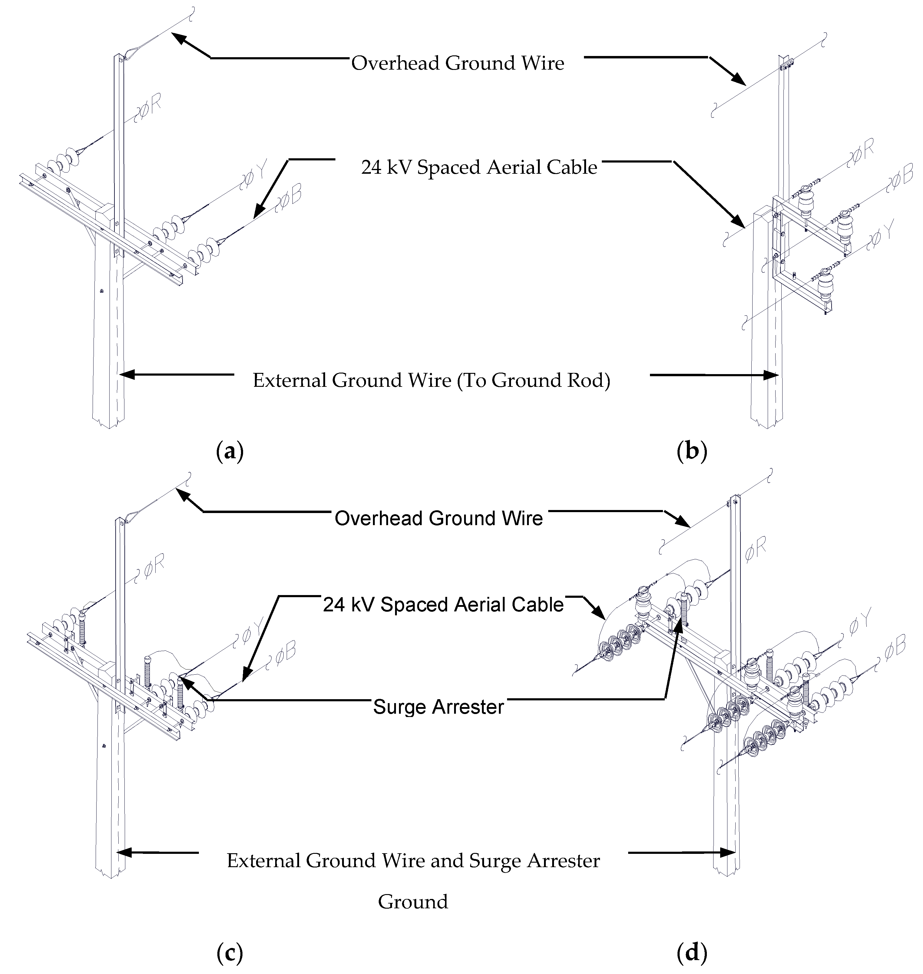
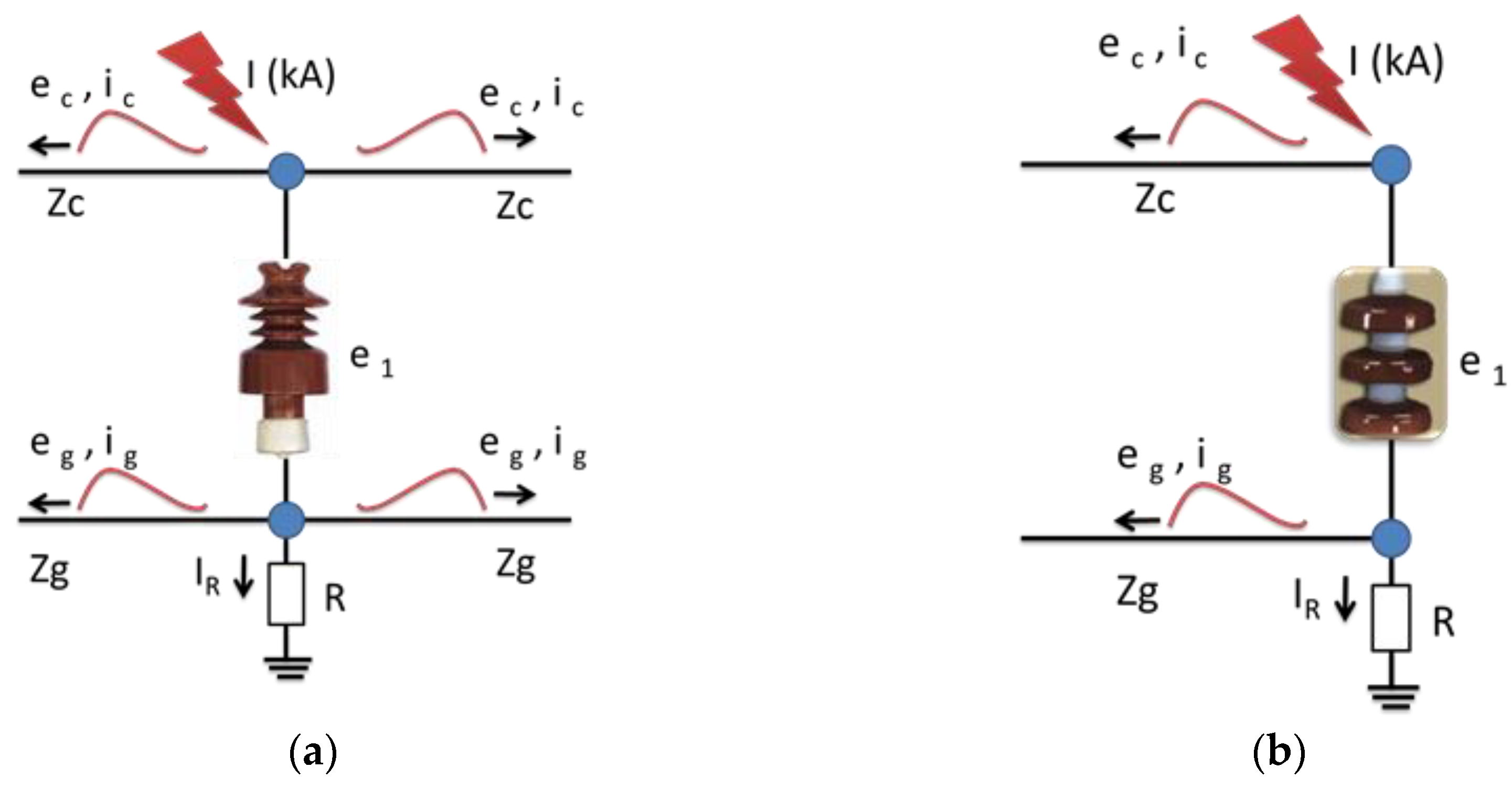
Figure 1.
Distribution line system arrangement used for analysis; (a) Single dead-end structure (end of the line); (b) Angle support structure (middle of the line); (c) Single dead-end structure with arrester (end of the line); (d) Double dead-end structure with arrester (middle of the line).
Figure 1.
Distribution line system arrangement used for analysis; (a) Single dead-end structure (end of the line); (b) Angle support structure (middle of the line); (c) Single dead-end structure with arrester (end of the line); (d) Double dead-end structure with arrester (middle of the line).
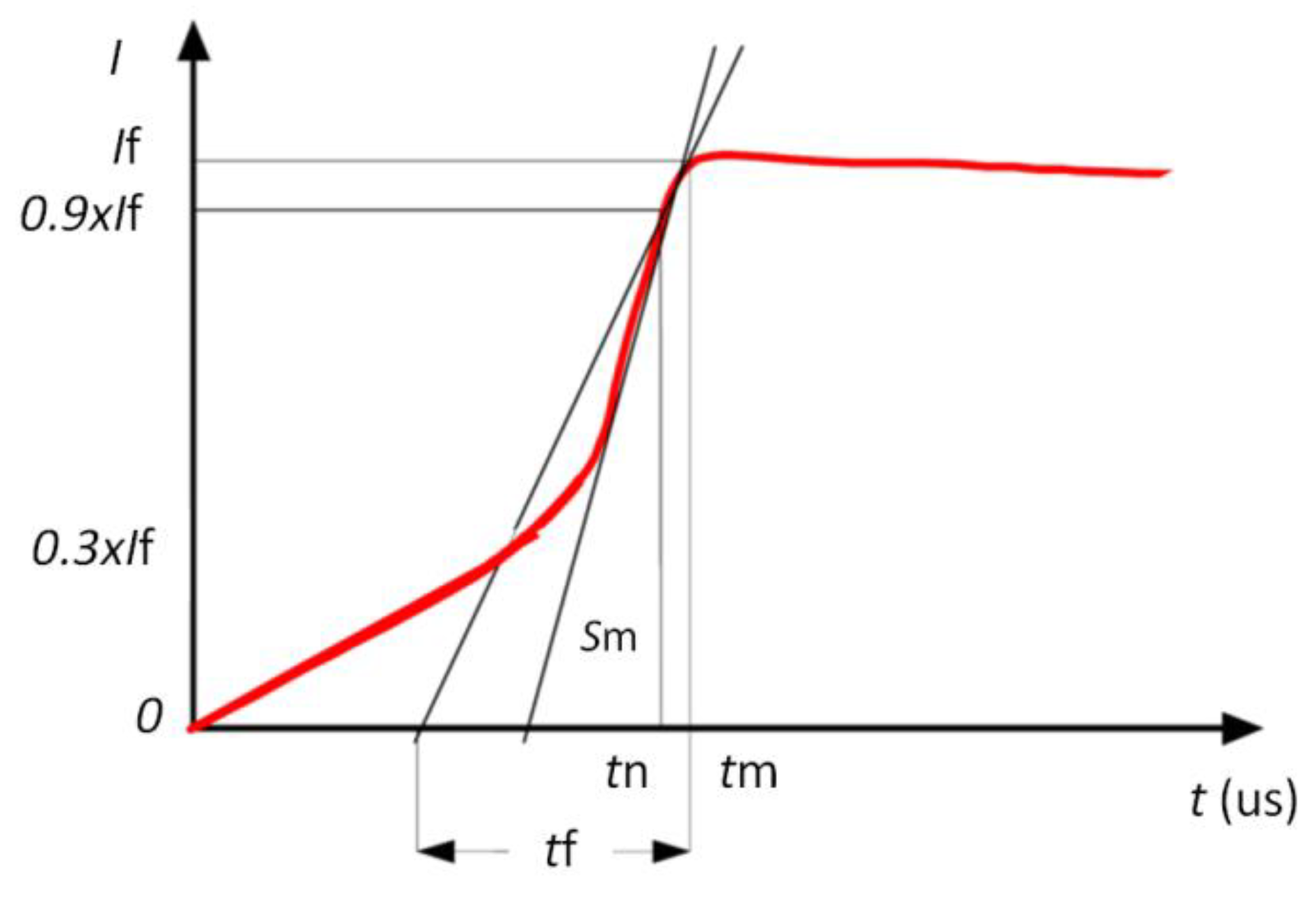
Figure 2.
International Council on Large Electric Systems (CIGRE) concave shape of the lightning current waveform.
Figure 2.
International Council on Large Electric Systems (CIGRE) concave shape of the lightning current waveform.
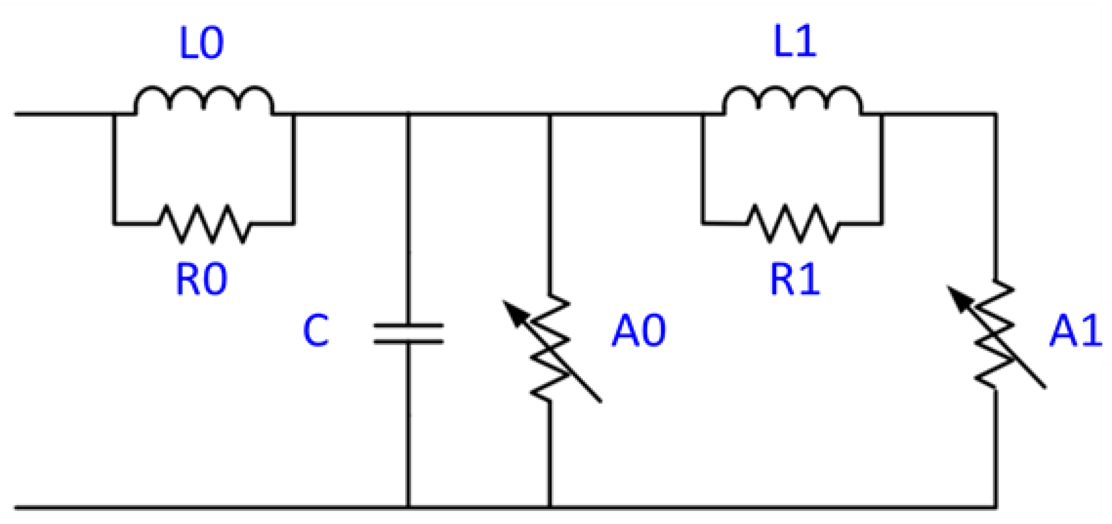
Figure 3.
Institute of Electrical and Electronics Engineers’ (IEEE) frequency-dependent model surge arrester.
Figure 3.
Institute of Electrical and Electronics Engineers’ (IEEE) frequency-dependent model surge arrester.
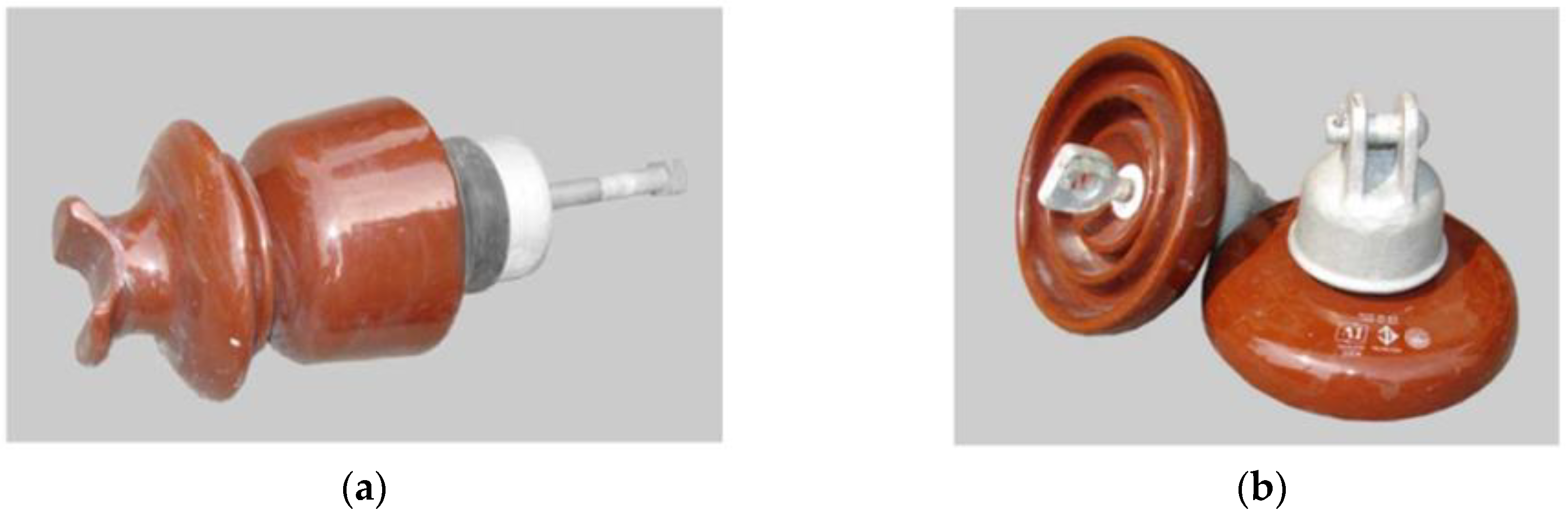
Figure 4.
Electrical insulators used in the Metropolitan Electricity Authority’s (MEA) 24 kV distribution line; (a) Pin-post insulator for the middle of the line; (b) Suspension insulator for the end of the line.
Figure 4.
Electrical insulators used in the Metropolitan Electricity Authority’s (MEA) 24 kV distribution line; (a) Pin-post insulator for the middle of the line; (b) Suspension insulator for the end of the line.
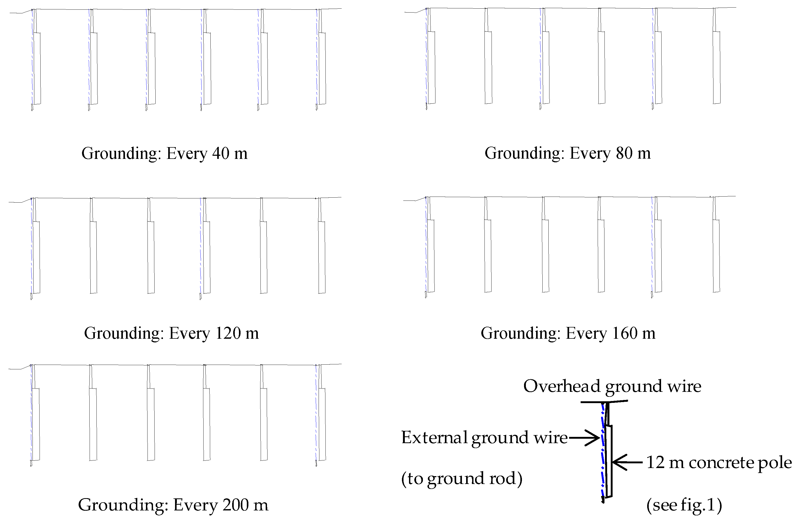
Figure 5.
Different grounding distance of overhead ground wire.
Figure 5.
Different grounding distance of overhead ground wire.
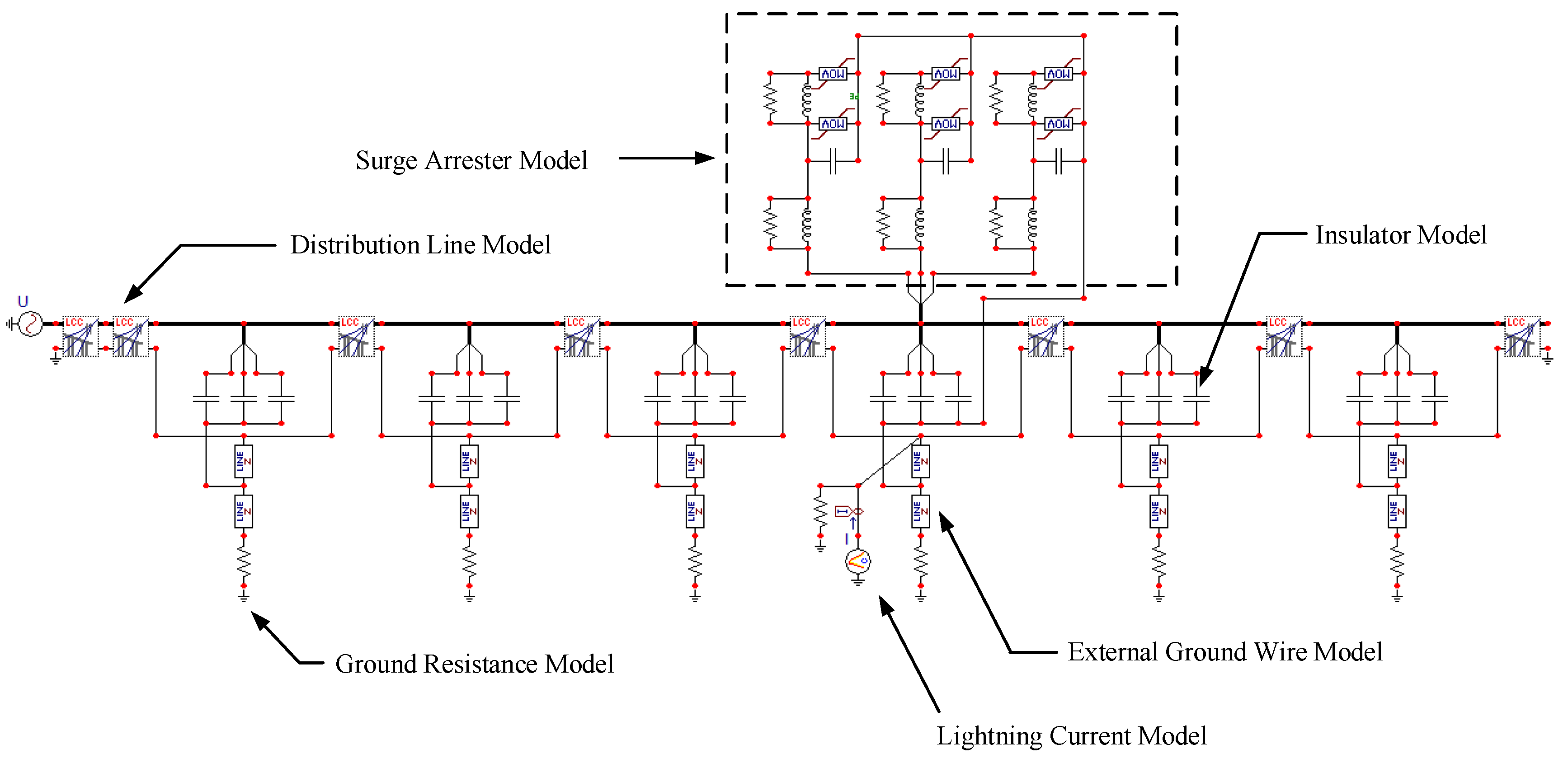
Figure 6.
Simulation model in the Alternative Transients Program/Electromagnetic Transients Program (ATP/EMTP).
Figure 6.
Simulation model in the Alternative Transients Program/Electromagnetic Transients Program (ATP/EMTP).
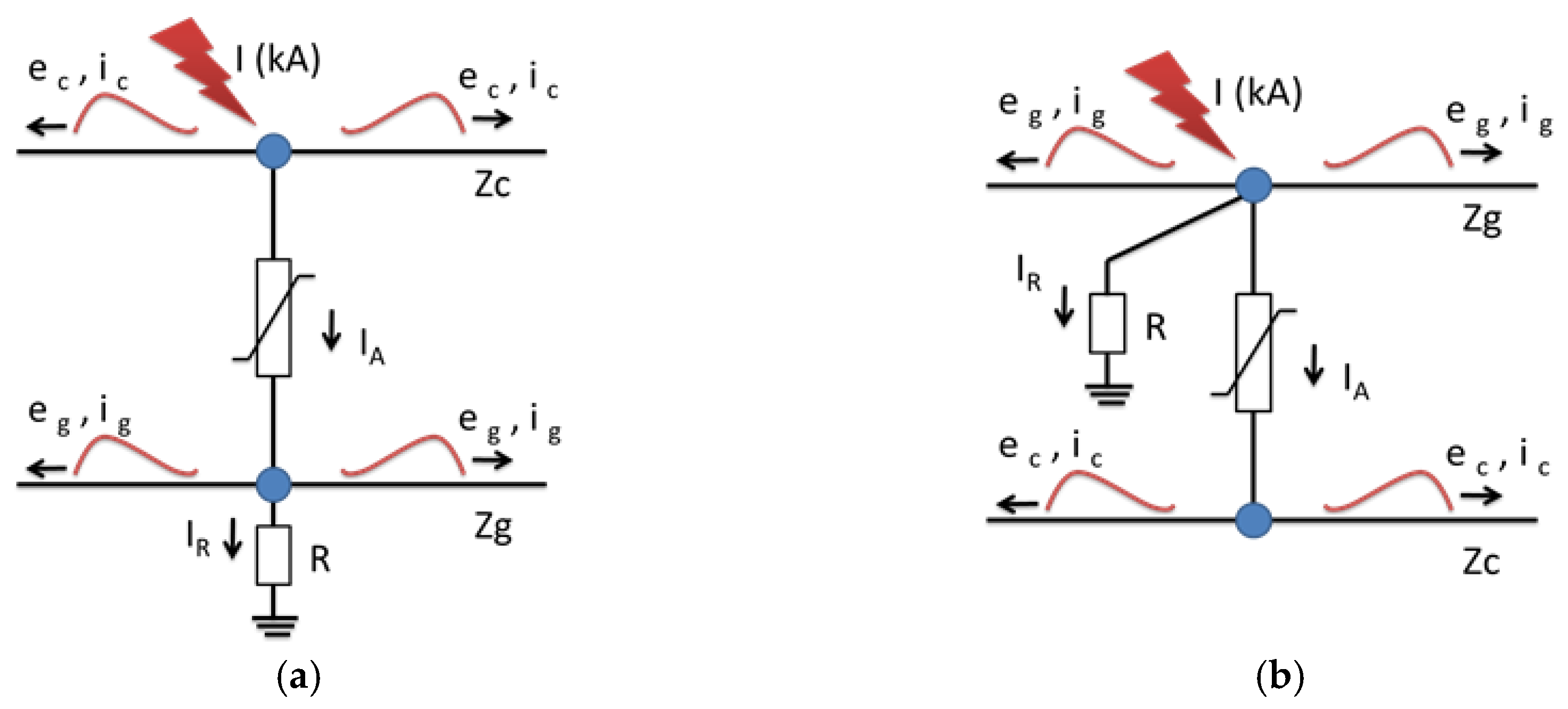
Figure 7.
Result of a lightning strike to the phase conductor; (a) Strike to the phase conductor (middle); (b) Strike to the phase conductor (end).
Figure 7.
Result of a lightning strike to the phase conductor; (a) Strike to the phase conductor (middle); (b) Strike to the phase conductor (end).
Figure 8.
Voltage across the insulator following a lightning strike to the phase conductor (lightning current wave shape = 4.12/77.5 μs, lightning current = 40 kA); (a) Strike to the middle of the phase conductor; (b) Strike to the end of the phase conductor.
Figure 8.
Voltage across the insulator following a lightning strike to the phase conductor (lightning current wave shape = 4.12/77.5 μs, lightning current = 40 kA); (a) Strike to the middle of the phase conductor; (b) Strike to the end of the phase conductor.
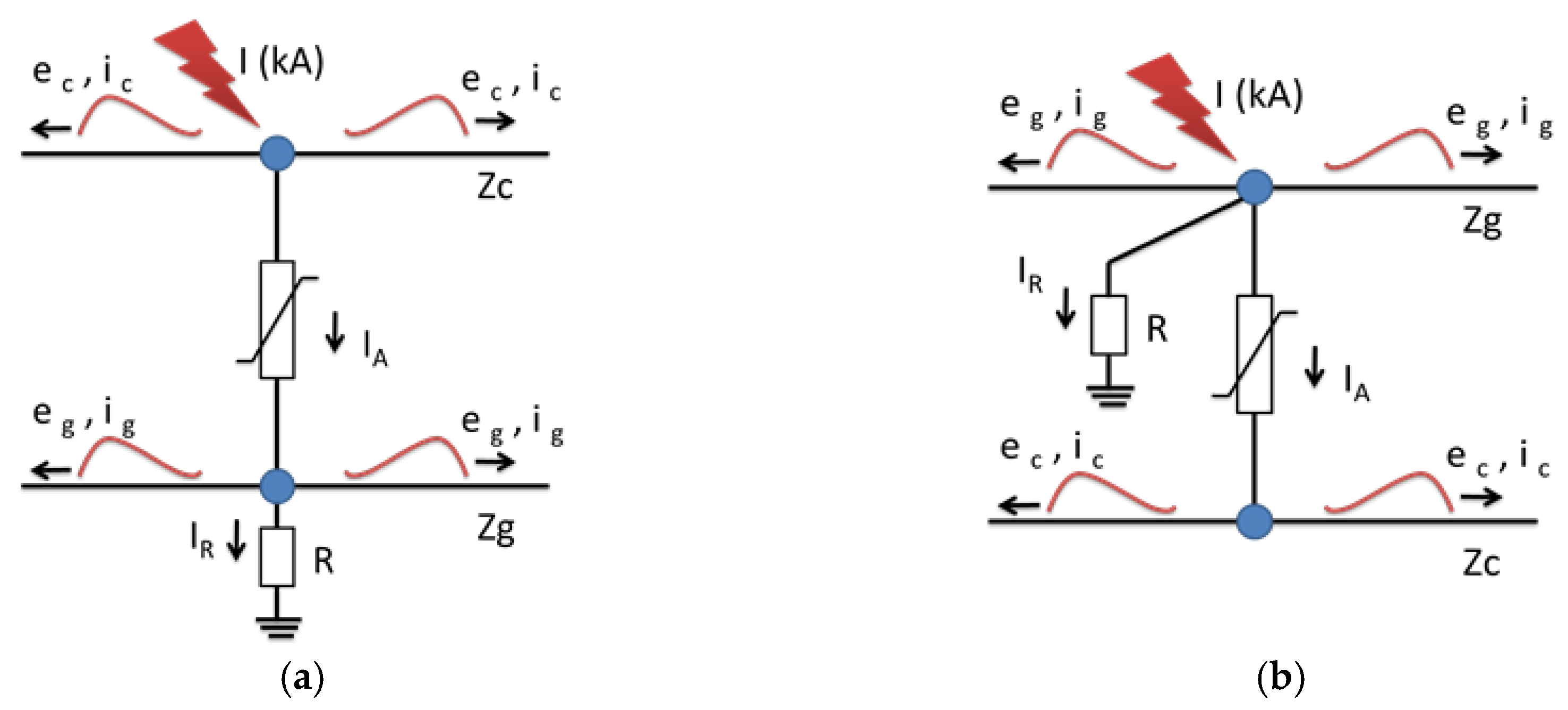
Figure 9.
Result of a lightning strike to the overhead ground wire; (a) Strike to the overhead ground wire; (b) Reflected wave voltage.
Figure 9.
Result of a lightning strike to the overhead ground wire; (a) Strike to the overhead ground wire; (b) Reflected wave voltage.
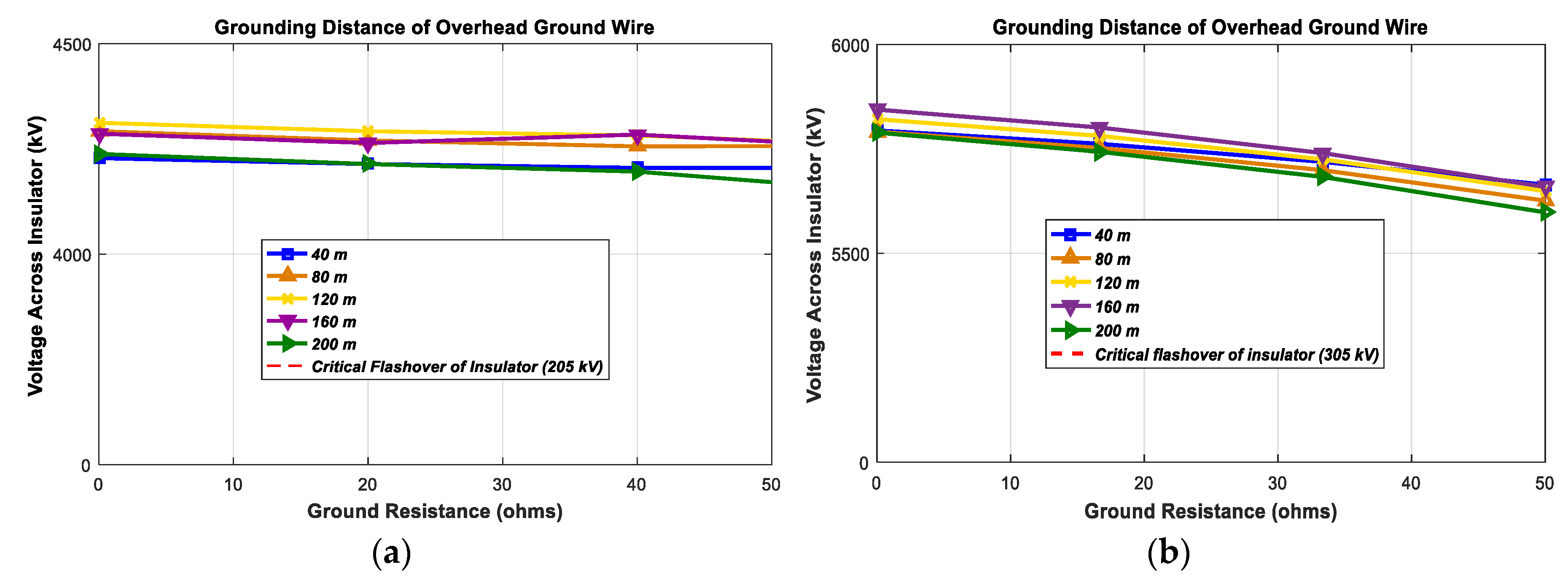
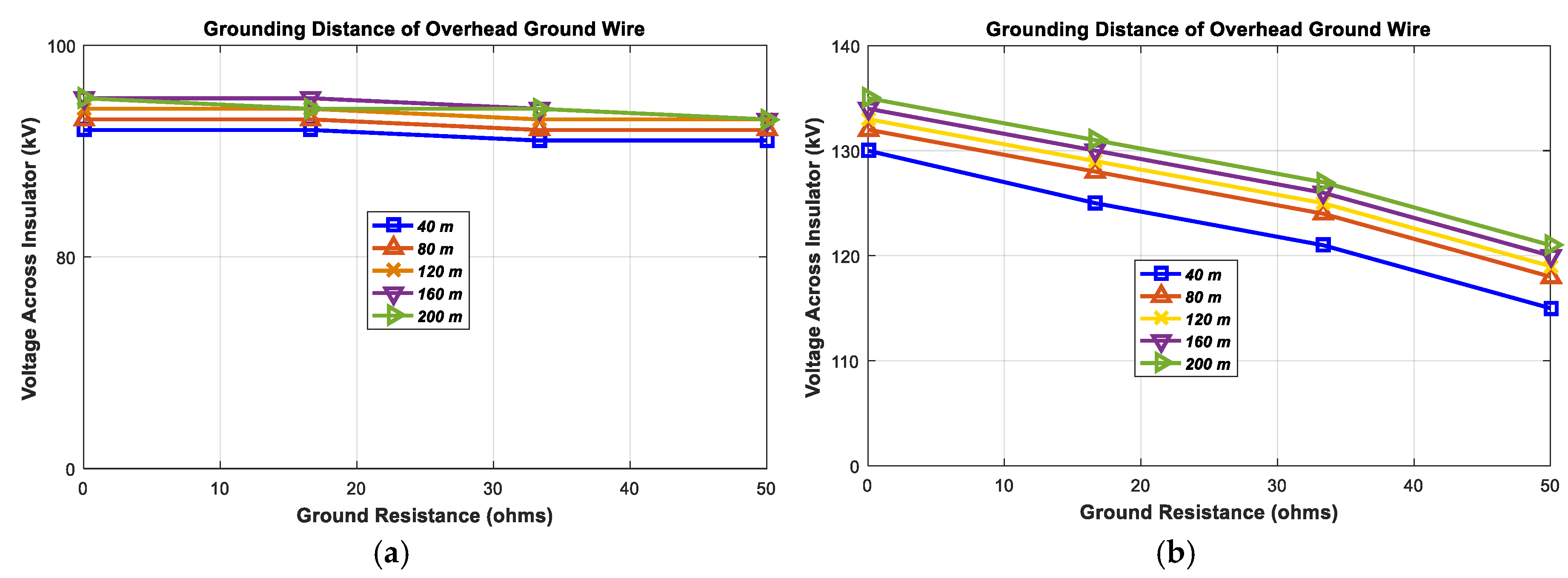
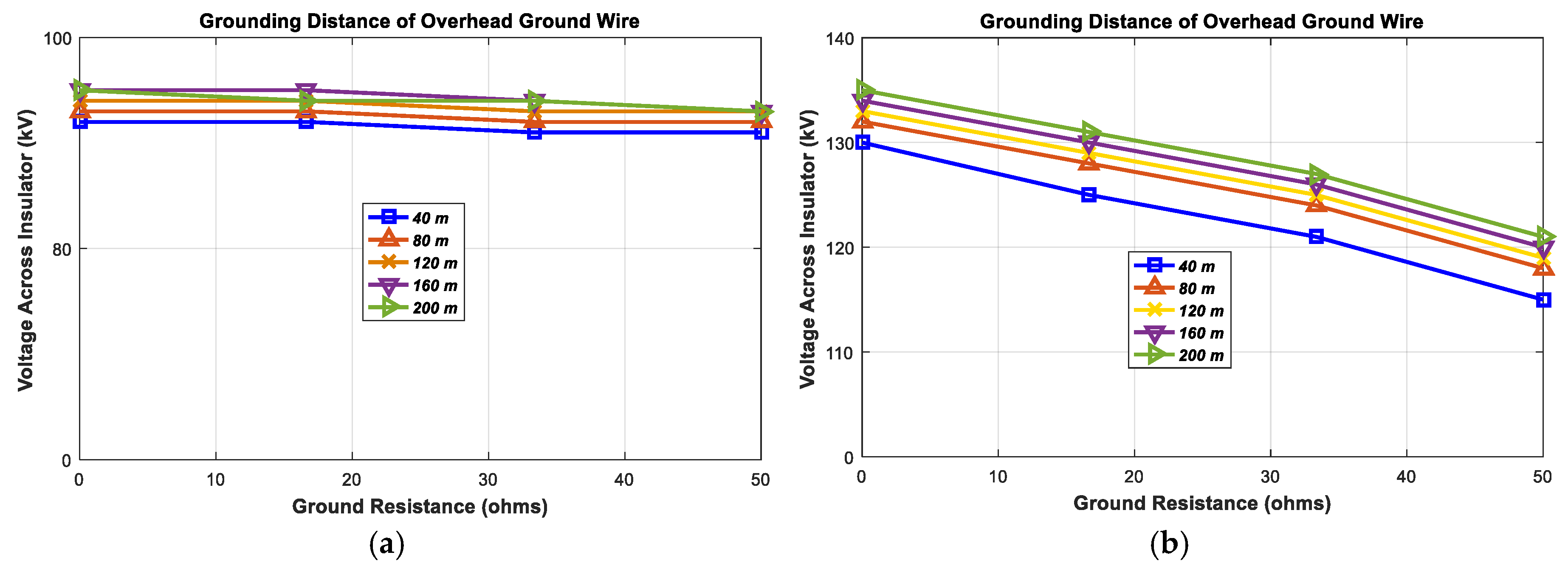
Figure 10.
Voltage across the insulator resulting from a lightning strike to the overhead ground wire (lightning current wave shape = 4.12/77.5 μs, lightning current = 40 kA); (a) Strike to the middle of the overhead ground wire; (b) Strike to the end of the overhead ground wire.
Figure 10.
Voltage across the insulator resulting from a lightning strike to the overhead ground wire (lightning current wave shape = 4.12/77.5 μs, lightning current = 40 kA); (a) Strike to the middle of the overhead ground wire; (b) Strike to the end of the overhead ground wire.
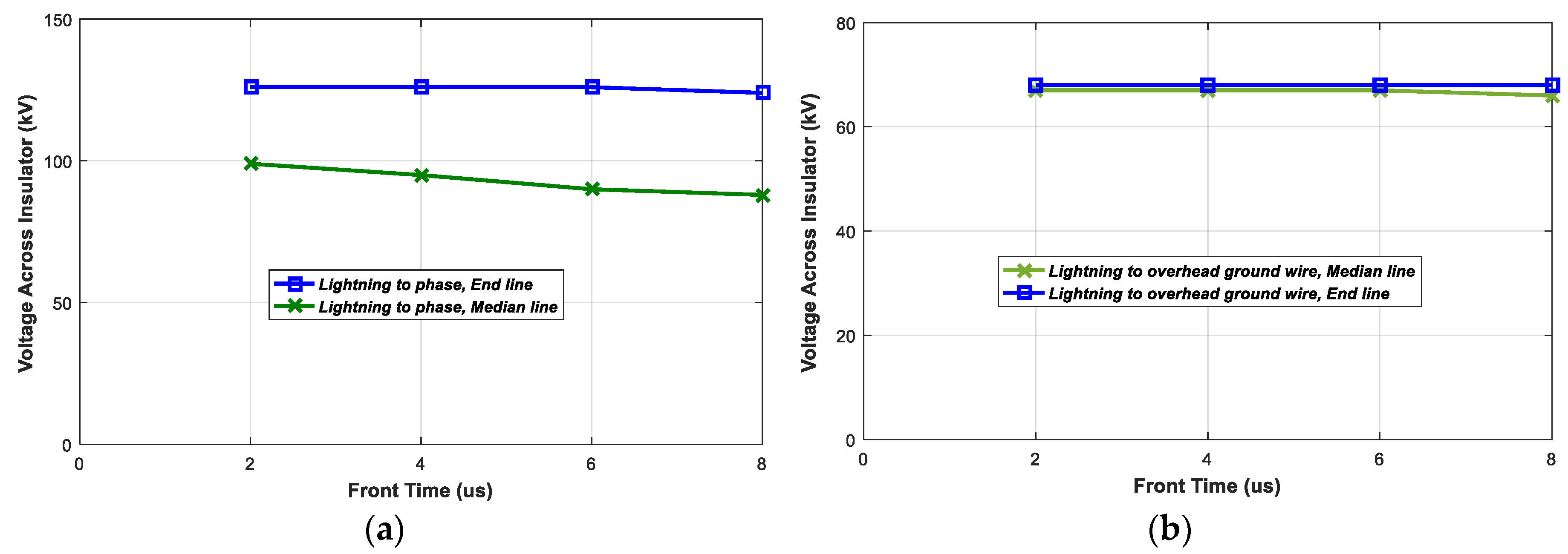
Figure 11.
Voltage across the insulator for different front time lightning current wave shapes (grounding distance of overhead ground wire = 200 m, lightning current = 40 kA, ground resistance = 10 Ω, tail time = 77.5 μs); (a) Strike to the phase conductor; (b) Strike to the overhead ground wire.
Figure 11.
Voltage across the insulator for different front time lightning current wave shapes (grounding distance of overhead ground wire = 200 m, lightning current = 40 kA, ground resistance = 10 Ω, tail time = 77.5 μs); (a) Strike to the phase conductor; (b) Strike to the overhead ground wire.
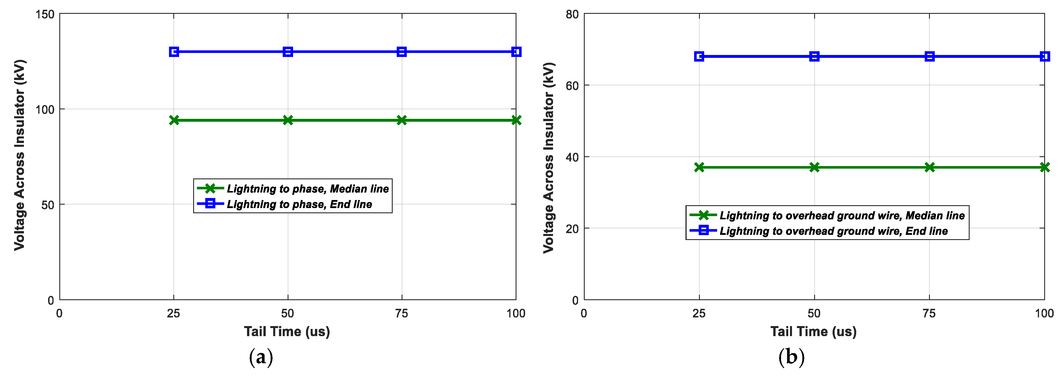
Figure 12.
Voltage across the insulator for different tail time lightning current wave shapes (grounding distance of overhead ground wire = 200 m, lightning current = 40 kA, ground resistance = 10 Ω, front time = 4.12 μs); (a) Strike to the phase conductor; (b) Strike to the overhead ground wire.
Figure 12.
Voltage across the insulator for different tail time lightning current wave shapes (grounding distance of overhead ground wire = 200 m, lightning current = 40 kA, ground resistance = 10 Ω, front time = 4.12 μs); (a) Strike to the phase conductor; (b) Strike to the overhead ground wire.
Figure 13.
Result of a lightning strike to the phase conductor and overhead ground wire when the arrester is installed; (a) Strike to the phase conductor; (b) Strike to the overhead ground wire.
Figure 13.
Result of a lightning strike to the phase conductor and overhead ground wire when the arrester is installed; (a) Strike to the phase conductor; (b) Strike to the overhead ground wire.
Figure 14.
Voltage across the insulator as a result of a lightning strike to the phase conductor (lightning current wave shape = 4.12/77.5 μs, lightning current = 40 kA); (a) Strike to the middle of the phase conductor; (b) Strike to the end of the phase conductor.
Figure 14.
Voltage across the insulator as a result of a lightning strike to the phase conductor (lightning current wave shape = 4.12/77.5 μs, lightning current = 40 kA); (a) Strike to the middle of the phase conductor; (b) Strike to the end of the phase conductor.
Figure 15.
Voltage across the insulator in case of a lightning strike to the overhead ground wire (lightning current wave shape = 4.12/77.5 μs, lightning current = 40 kA); (a) Strike to the middle of the overhead ground wire; (b) Strike to the end of the phase conductor.
Figure 15.
Voltage across the insulator in case of a lightning strike to the overhead ground wire (lightning current wave shape = 4.12/77.5 μs, lightning current = 40 kA); (a) Strike to the middle of the overhead ground wire; (b) Strike to the end of the phase conductor.
Figure 16.
Voltage across the insulator for different front time lightning current wave shapes (grounding distance of overhead ground wire = 200 m, ground resistance = 10 Ω, tail time = 77.5 μs); (a) Strike to the phase conductor; (b) Strike to the overhead ground wire.
Figure 16.
Voltage across the insulator for different front time lightning current wave shapes (grounding distance of overhead ground wire = 200 m, ground resistance = 10 Ω, tail time = 77.5 μs); (a) Strike to the phase conductor; (b) Strike to the overhead ground wire.
Figure 17.
Voltage across the insulator for different tail time lightning current wave shapes (grounding distance of overhead ground wire = 200 m, ground resistance = 10 Ω, front time = 4.12 μs); (a) Strike to the phase conductor; (b) Strike to the overhead ground wire.
Figure 17.
Voltage across the insulator for different tail time lightning current wave shapes (grounding distance of overhead ground wire = 200 m, ground resistance = 10 Ω, front time = 4.12 μs); (a) Strike to the phase conductor; (b) Strike to the overhead ground wire.
Figure 18.
Result of a lightning strike to the phase conductor and overhead ground wire when an arrester is installed; (a) Strike to the phase conductor; (b) Strike to the overhead ground wire.
Figure 18.
Result of a lightning strike to the phase conductor and overhead ground wire when an arrester is installed; (a) Strike to the phase conductor; (b) Strike to the overhead ground wire.
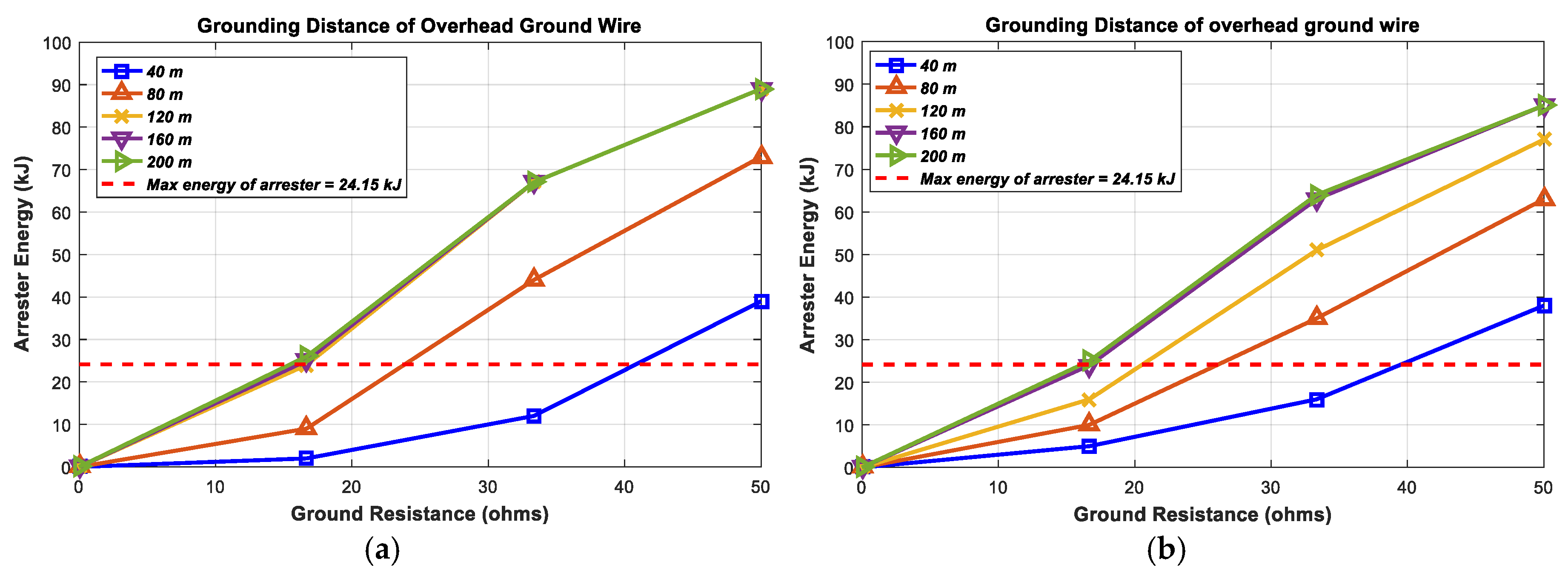
Figure 19.
Arrester energy discharge in the case of a lightning strike to the phase conductor (lightning current wave shape = 4.12/77.5 μs, lightning current = 40 kA); (a) Strike to the middle of phase conductor; (b) Strike to the end of the phase conductor.
Figure 19.
Arrester energy discharge in the case of a lightning strike to the phase conductor (lightning current wave shape = 4.12/77.5 μs, lightning current = 40 kA); (a) Strike to the middle of phase conductor; (b) Strike to the end of the phase conductor.
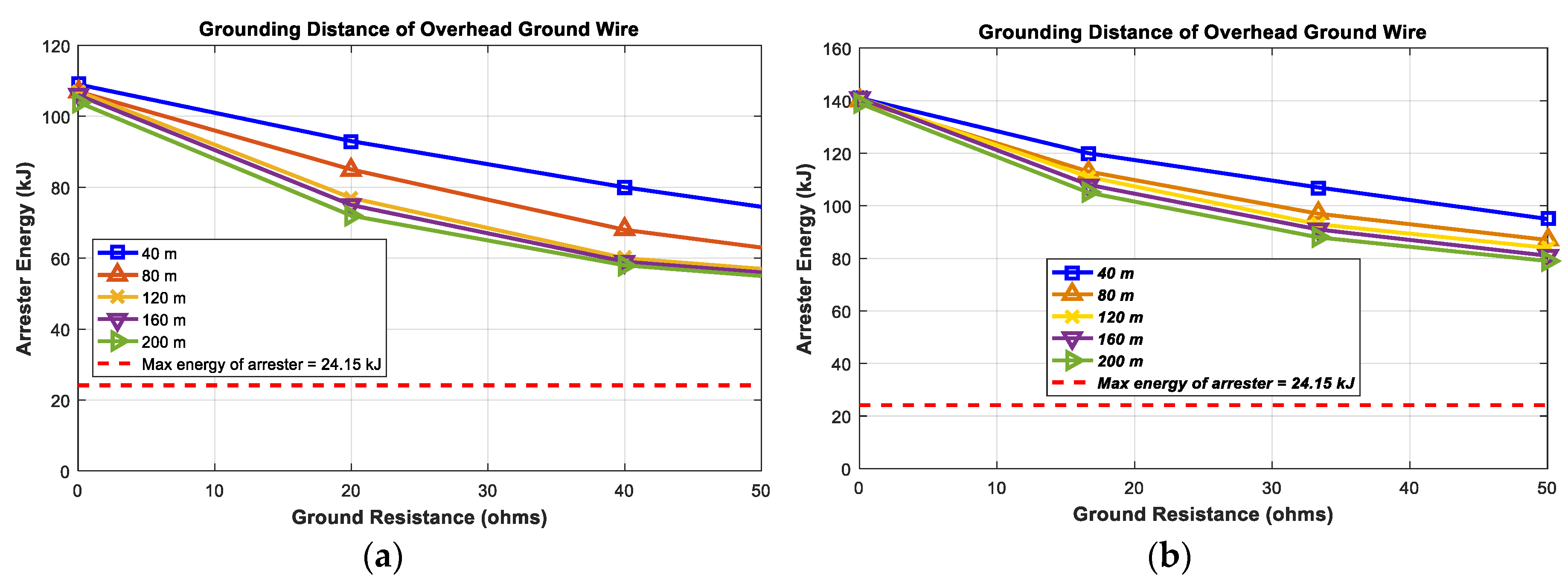
Figure 20.
Arrester energy discharge in the case of a lightning strike to the overhead ground wire (lightning current wave shape = 4.12/77.5 μs, lightning current = 40 kA); (a) Strike to the middle of the overhead ground wire; (b) Strike to the end of the overhead ground wire.
Figure 20.
Arrester energy discharge in the case of a lightning strike to the overhead ground wire (lightning current wave shape = 4.12/77.5 μs, lightning current = 40 kA); (a) Strike to the middle of the overhead ground wire; (b) Strike to the end of the overhead ground wire.
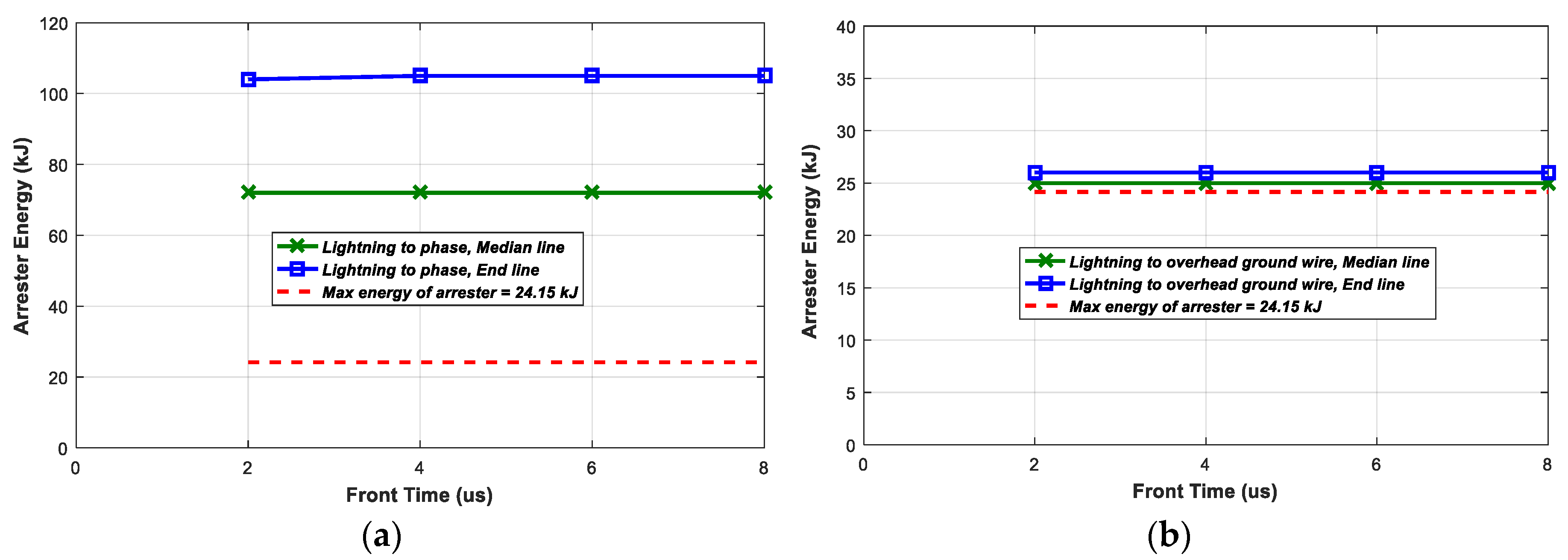
Figure 21.
Arrester energy discharge against front time lightning current waveforms (tail time = 77.5 μs, lightning current = 40 kA, 200 m grounding distance of the overhead ground wire and 10 Ω ground resistance); (a) Strike to the phase conductor; (b) Strike to the overhead ground wire.
Figure 21.
Arrester energy discharge against front time lightning current waveforms (tail time = 77.5 μs, lightning current = 40 kA, 200 m grounding distance of the overhead ground wire and 10 Ω ground resistance); (a) Strike to the phase conductor; (b) Strike to the overhead ground wire.
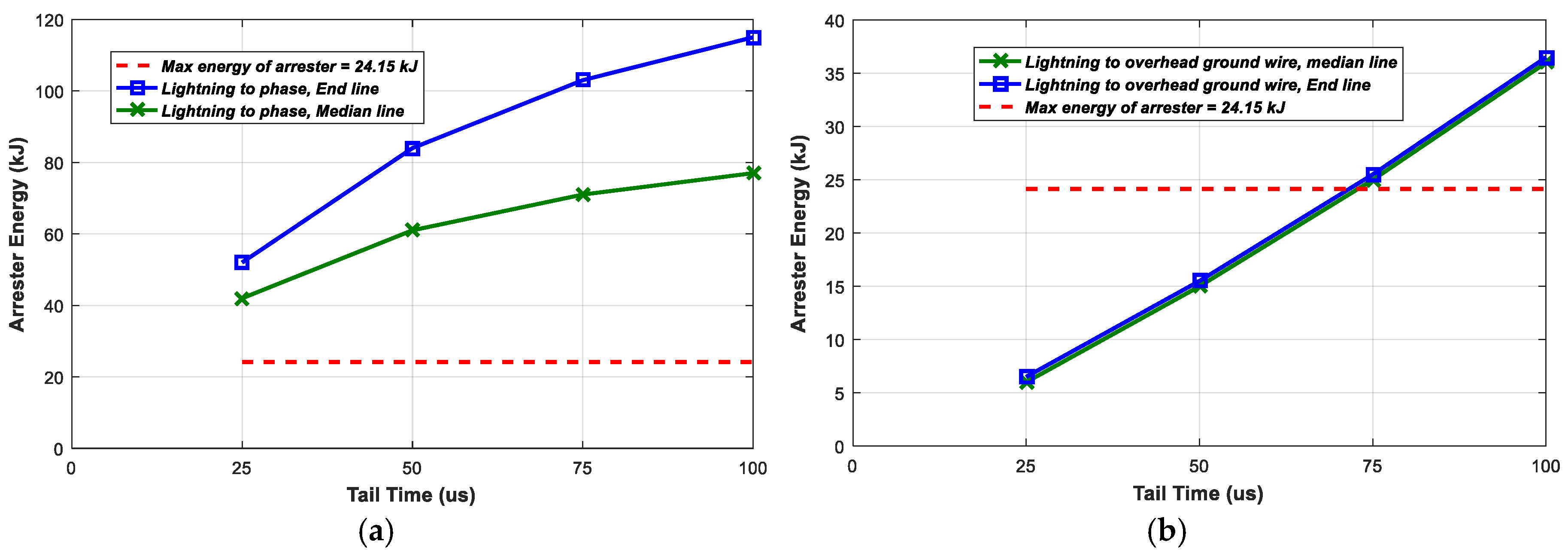
Figure 22.
Arrester energy discharge against tail time lightning current wave shapes (front time = 4.12 μs, lightning current = 40 kA, 200 m grounding distance of the overhead ground wire, 10 Ω ground resistance); (a) Strike to the phase conductor; (b) Strike to the overhead ground wire.
Figure 22.
Arrester energy discharge against tail time lightning current wave shapes (front time = 4.12 μs, lightning current = 40 kA, 200 m grounding distance of the overhead ground wire, 10 Ω ground resistance); (a) Strike to the phase conductor; (b) Strike to the overhead ground wire.
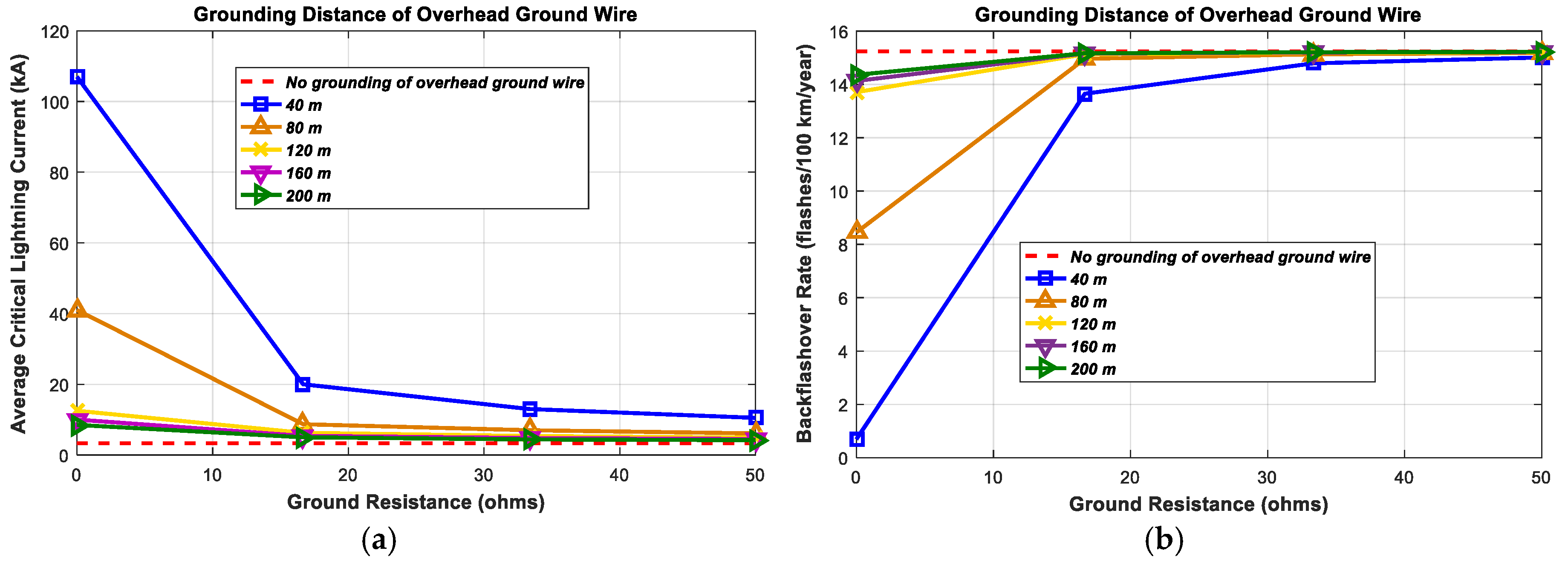
Figure 23.
Critical lightning current and the back-flashover rate (lightning current waveform = 4.12/77.5 μs); (a) Critical lightning current; (b) Back-flashover rate.
Figure 23.
Critical lightning current and the back-flashover rate (lightning current waveform = 4.12/77.5 μs); (a) Critical lightning current; (b) Back-flashover rate.
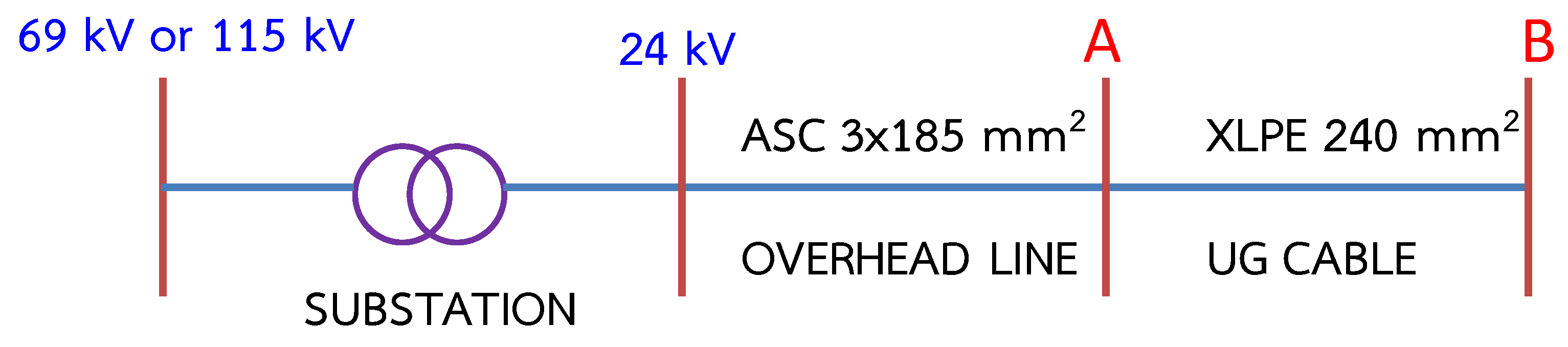
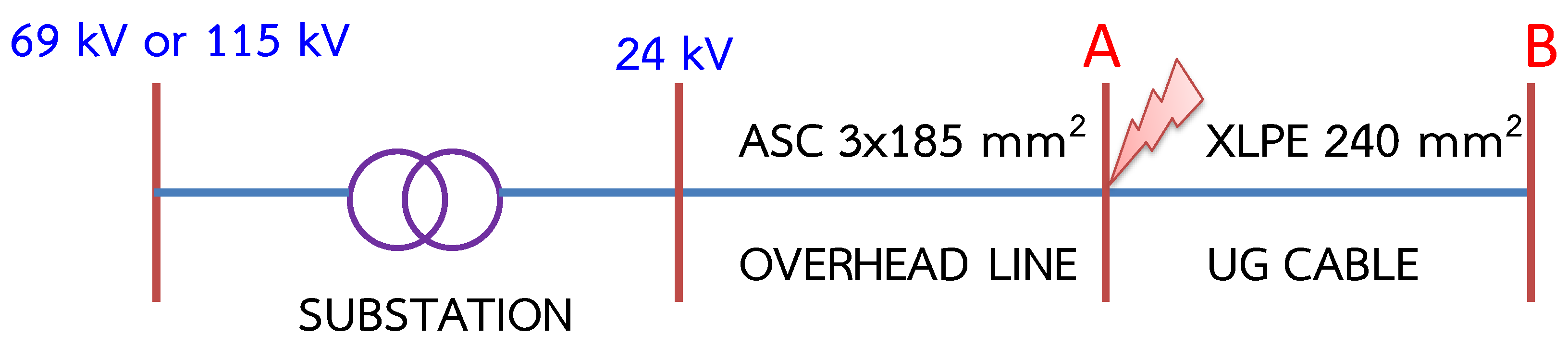
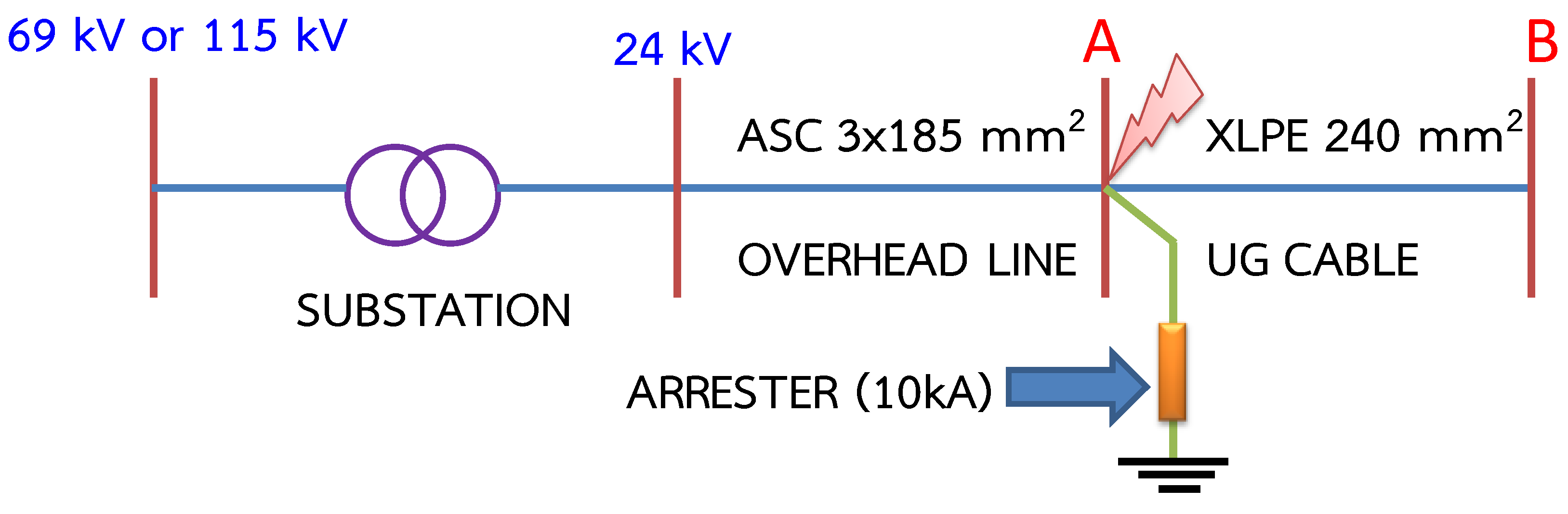
Figure 24.
The 24 kV distribution line system.
Figure 24.
The 24 kV distribution line system.
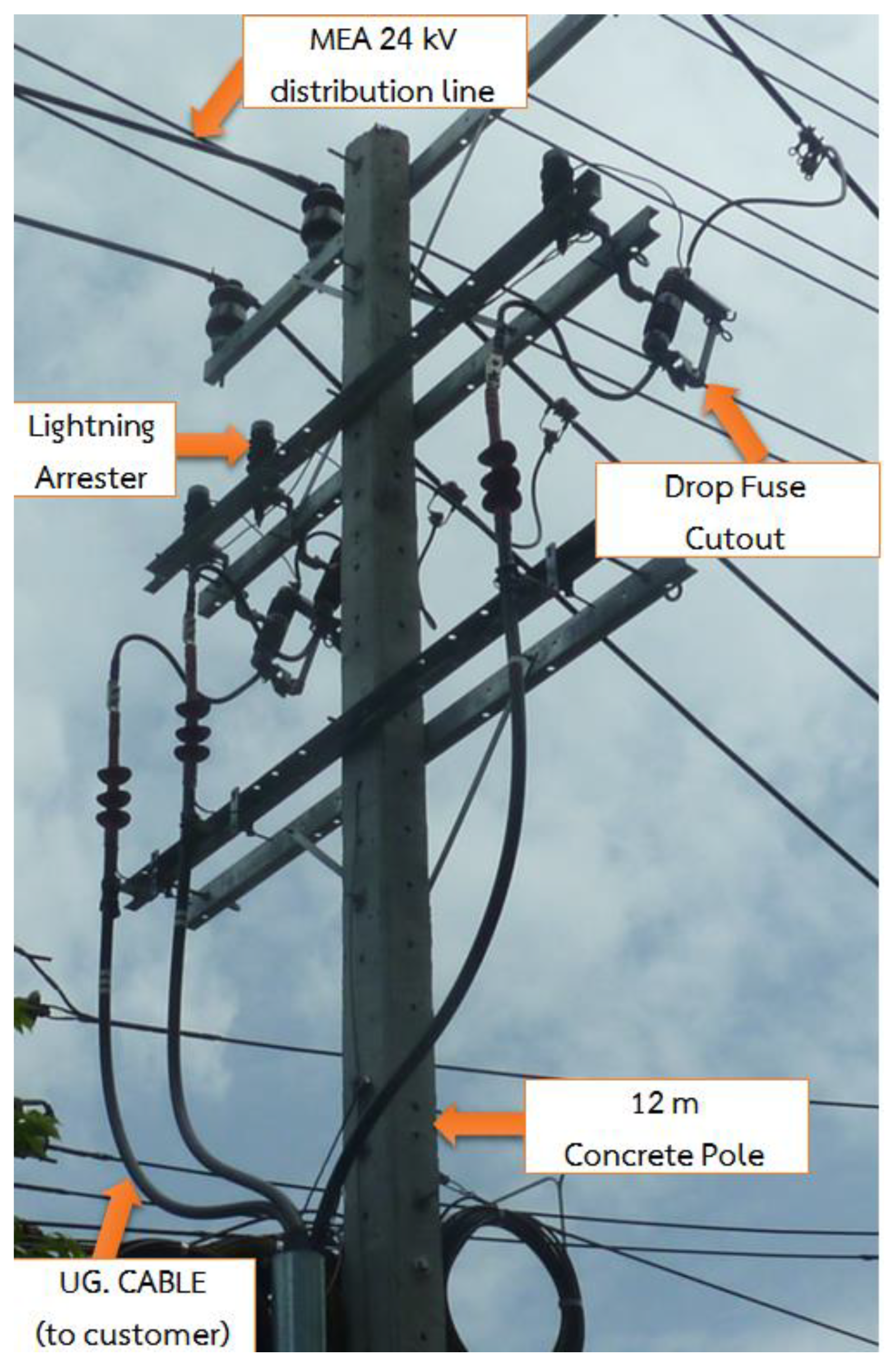
Figure 25.
Pole structure at point A that is situated between the overhead distribution line and the underground cable.
Figure 25.
Pole structure at point A that is situated between the overhead distribution line and the underground cable.
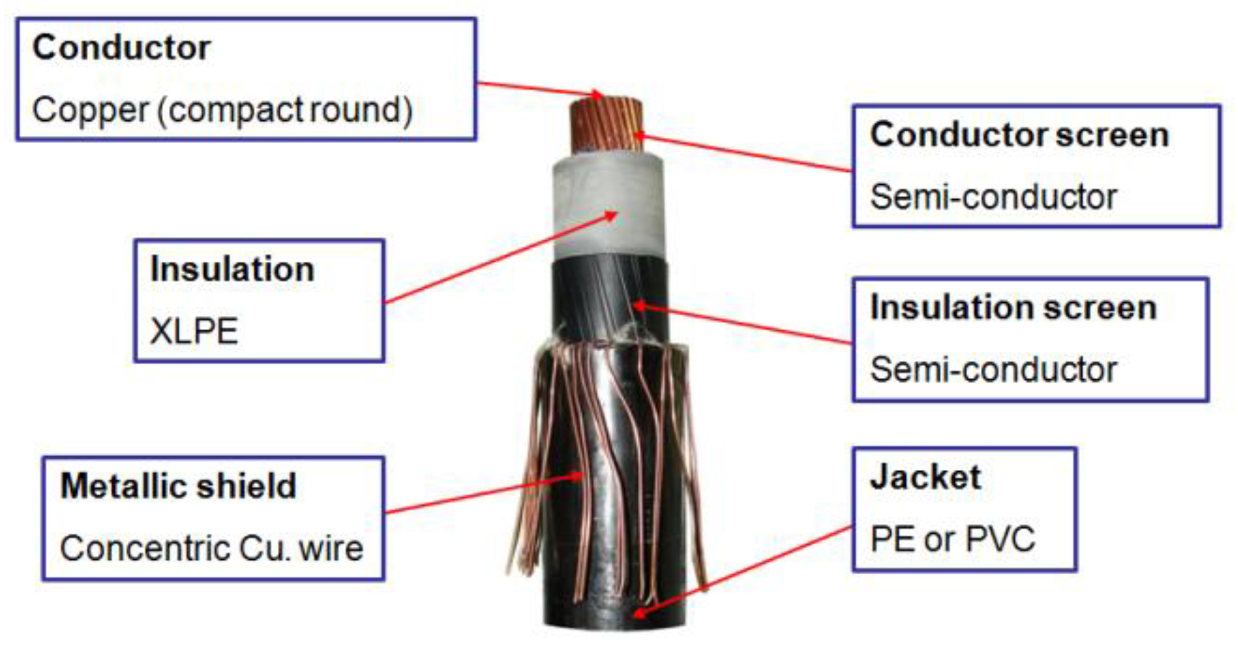
Figure 26.
The 24 kV cross-linked polyethylene (XLPE) underground cable structure.
Figure 26.
The 24 kV cross-linked polyethylene (XLPE) underground cable structure.
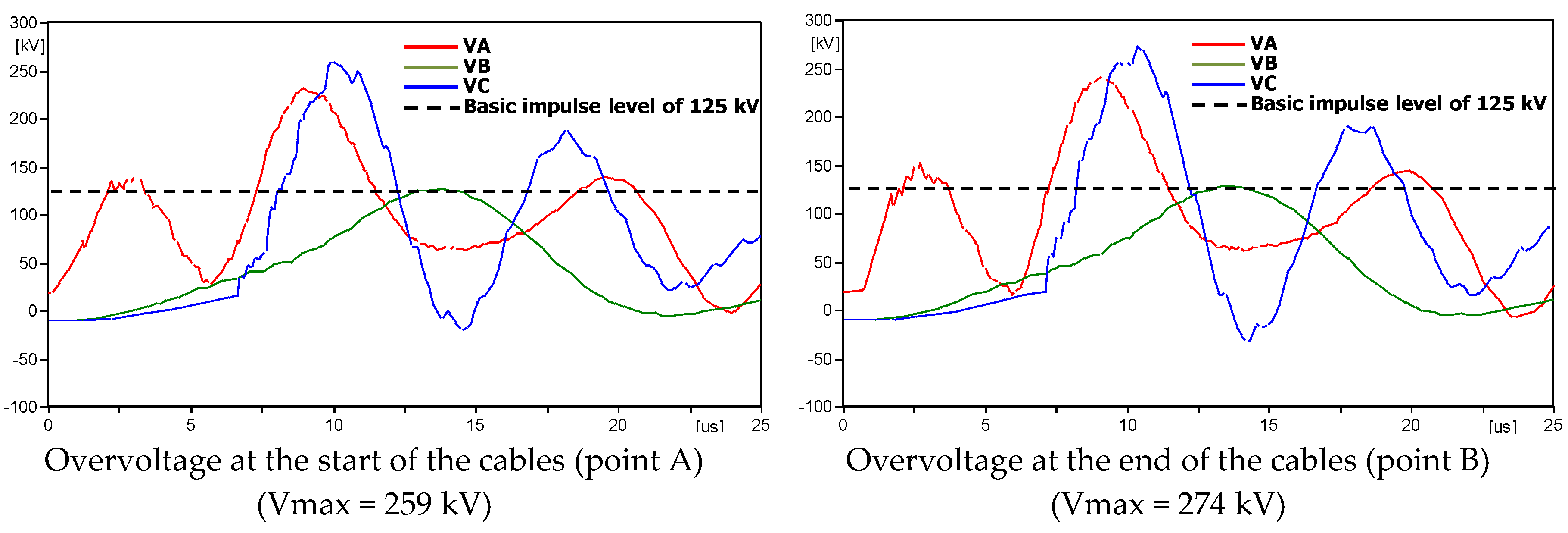
Figure 27.
System not protected by lightning arrester.
Figure 27.
System not protected by lightning arrester.
Figure 28.
A 100 m underground cable.
Figure 28.
A 100 m underground cable.
Figure 29.
A 200 m underground cable.
Figure 29.
A 200 m underground cable.
Figure 30.
A 300 m underground cable.
Figure 30.
A 300 m underground cable.
Figure 31.
A 400 m underground cable.
Figure 31.
A 400 m underground cable.
Figure 32.
A 500 m underground cable.
Figure 32.
A 500 m underground cable.
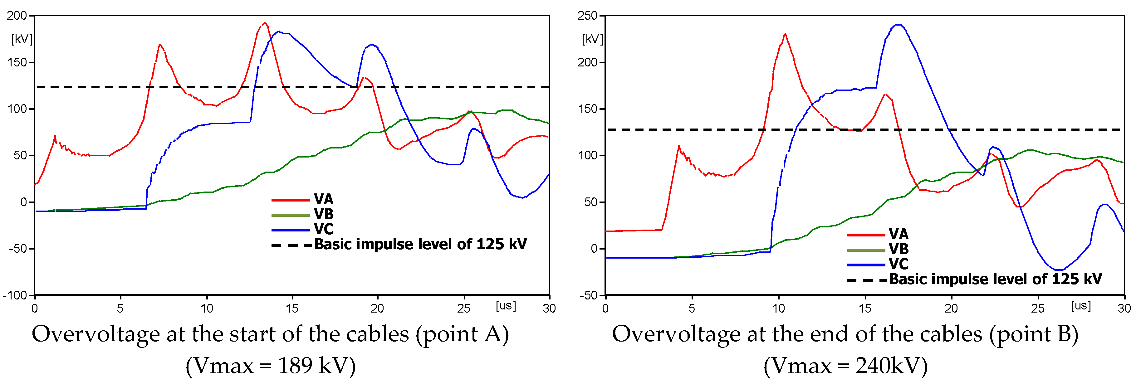
Figure 33.
A 600 m underground cable.
Figure 33.
A 600 m underground cable.
Figure 34.
System is protected by lightning arrester at the conjunction of overhead line and underground cables.
Figure 34.
System is protected by lightning arrester at the conjunction of overhead line and underground cables.
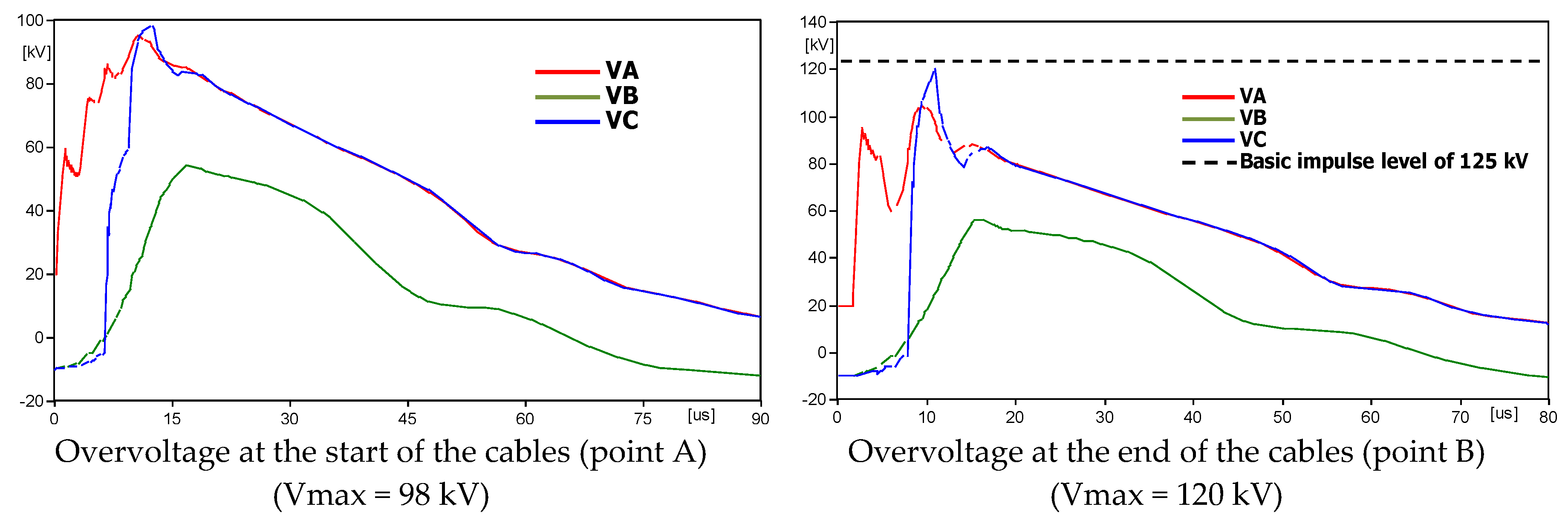
Figure 35.
A 100 m underground cable.
Figure 35.
A 100 m underground cable.
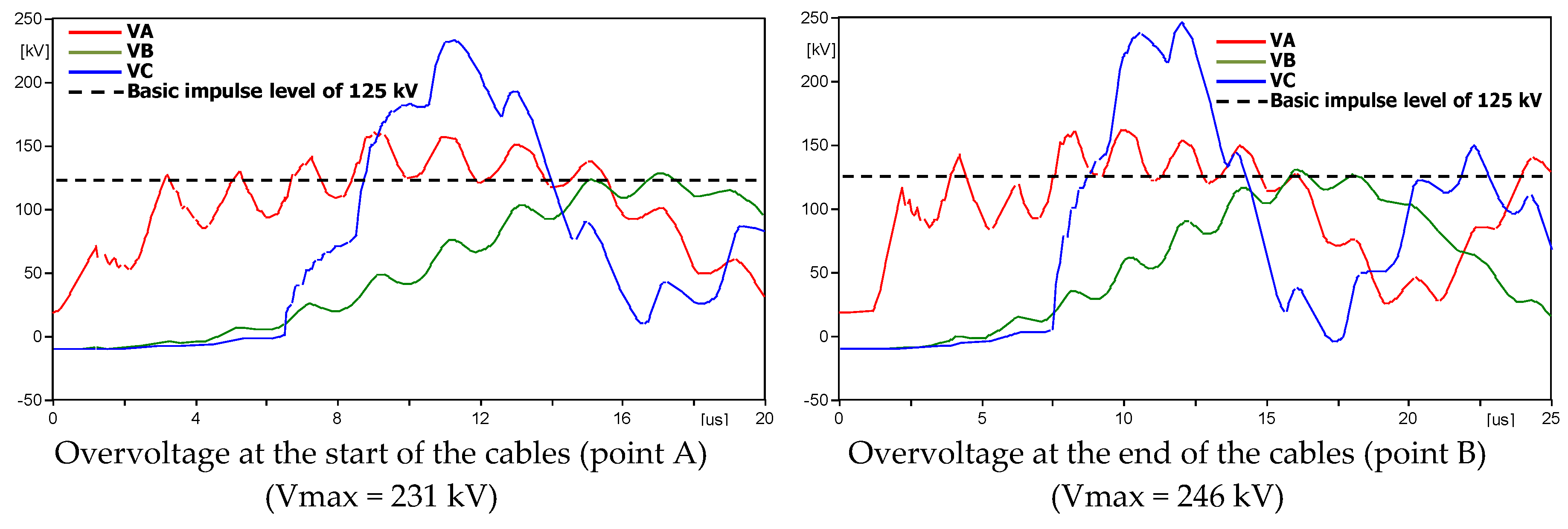
Figure 36.
A 200 m underground cable.
Figure 36.
A 200 m underground cable.
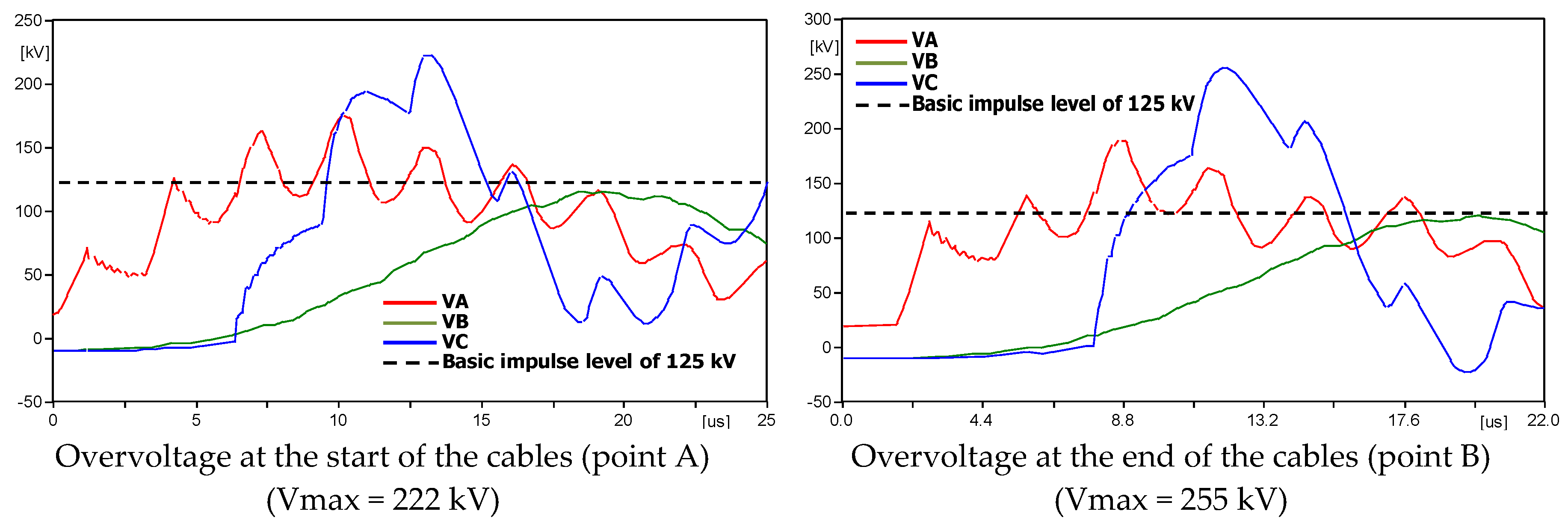
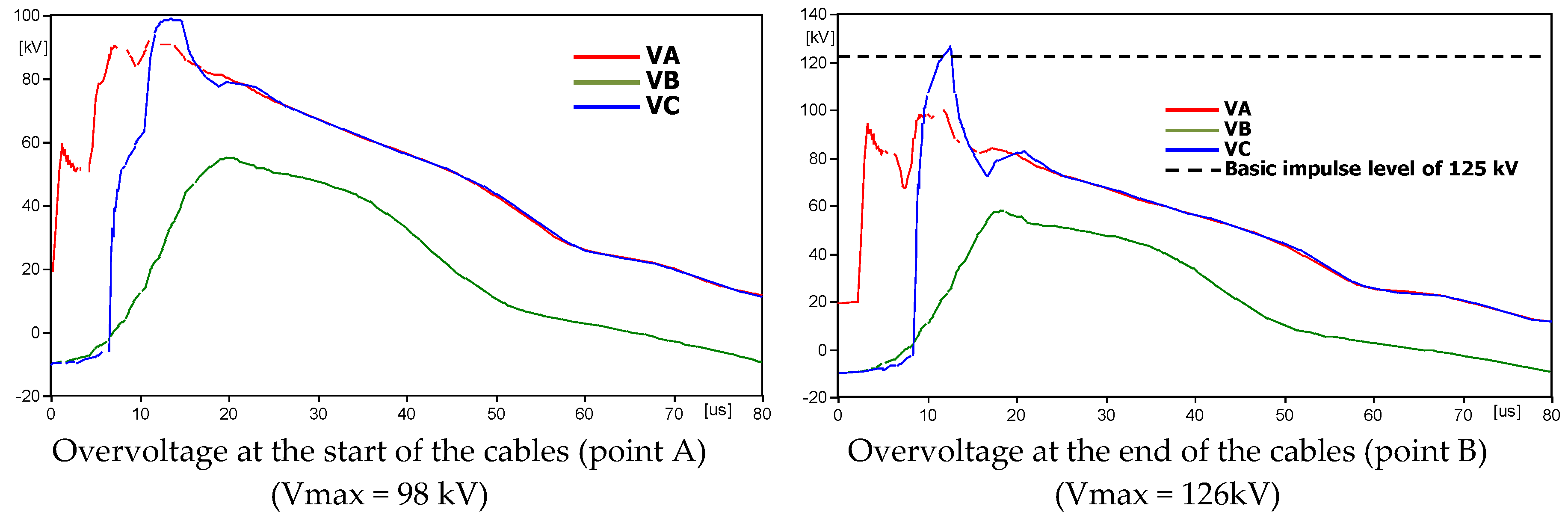
Figure 37.
A 300 m underground cable.
Figure 37.
A 300 m underground cable.
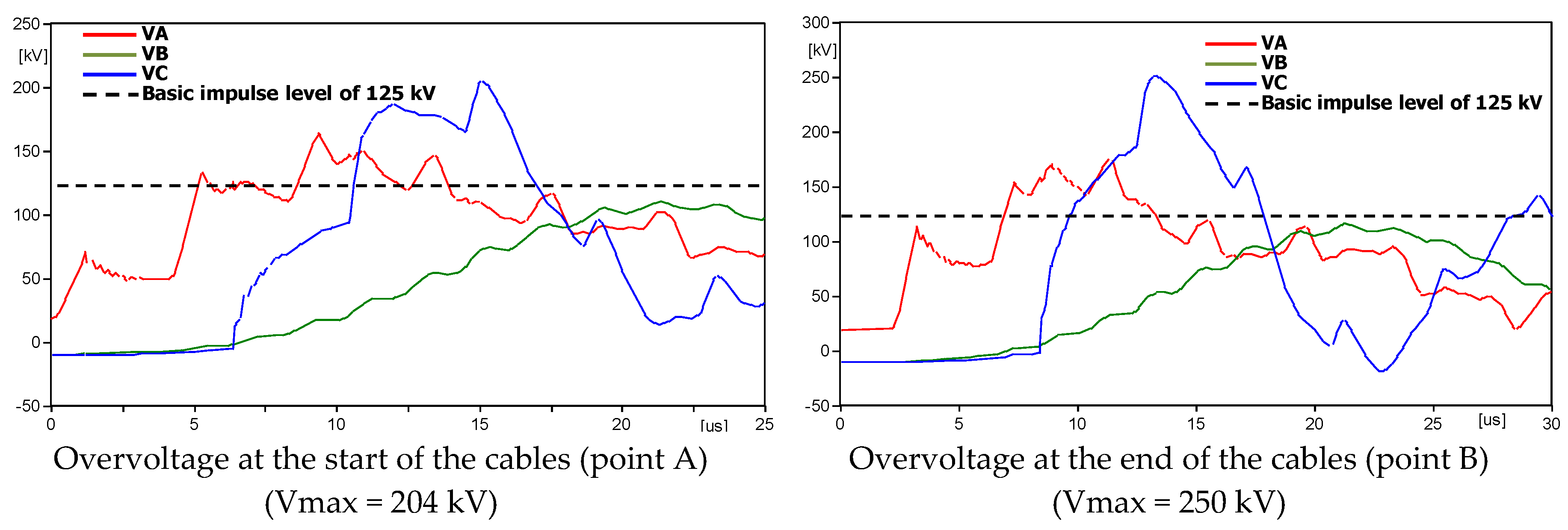
Figure 38.
A 400 m underground cable.
Figure 38.
A 400 m underground cable.
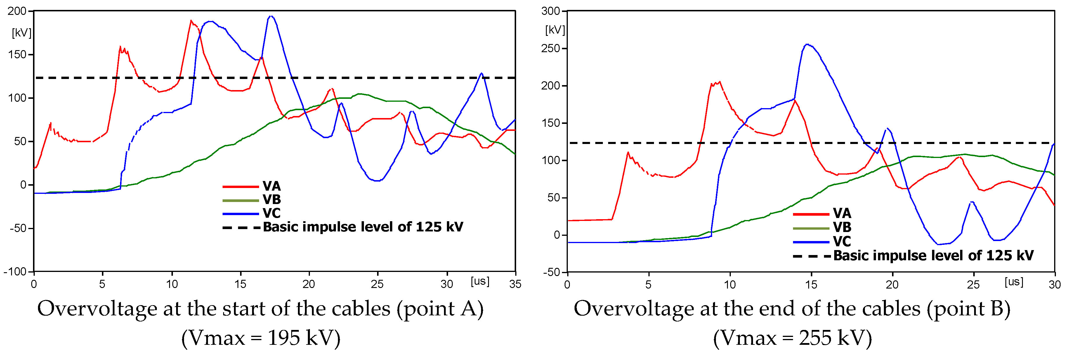
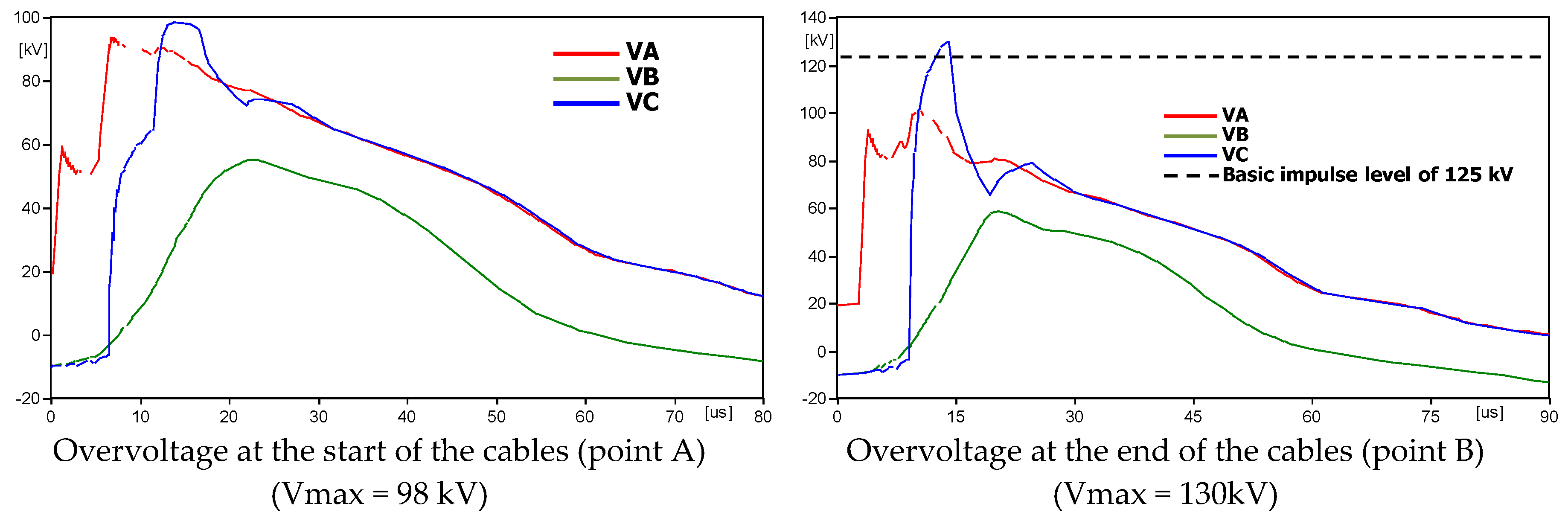
Figure 39.
A 500 m underground cable.
Figure 39.
A 500 m underground cable.
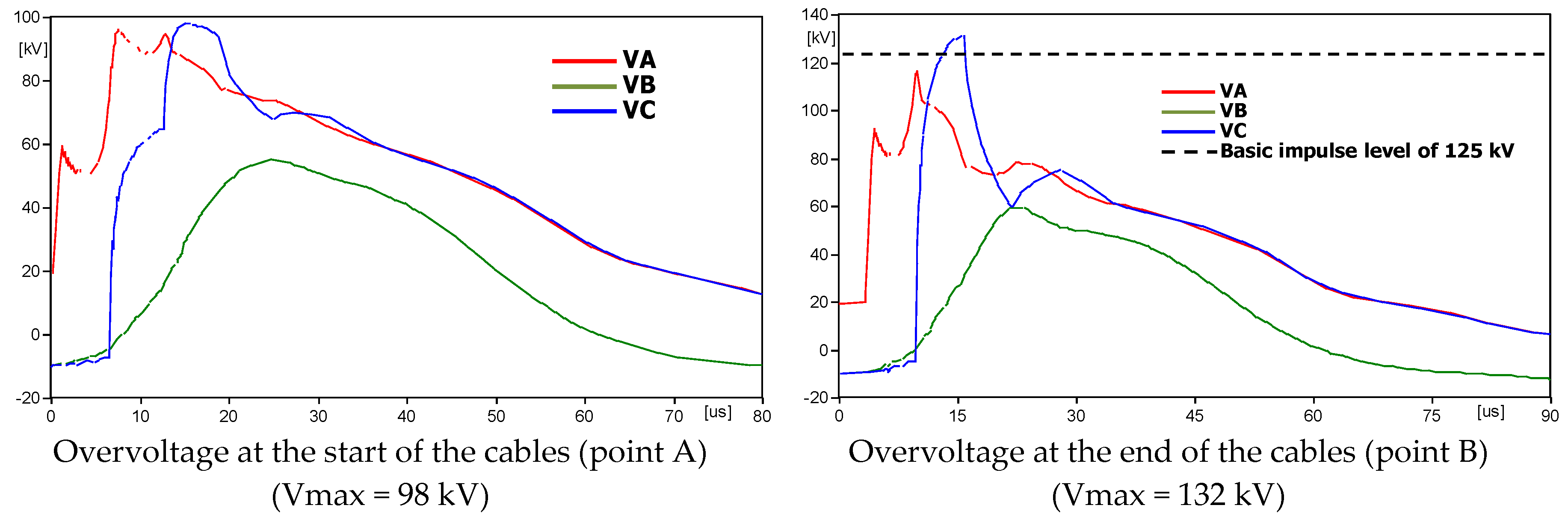
Figure 40.
A 600 m underground cable.
Figure 40.
A 600 m underground cable.
Figure 41.
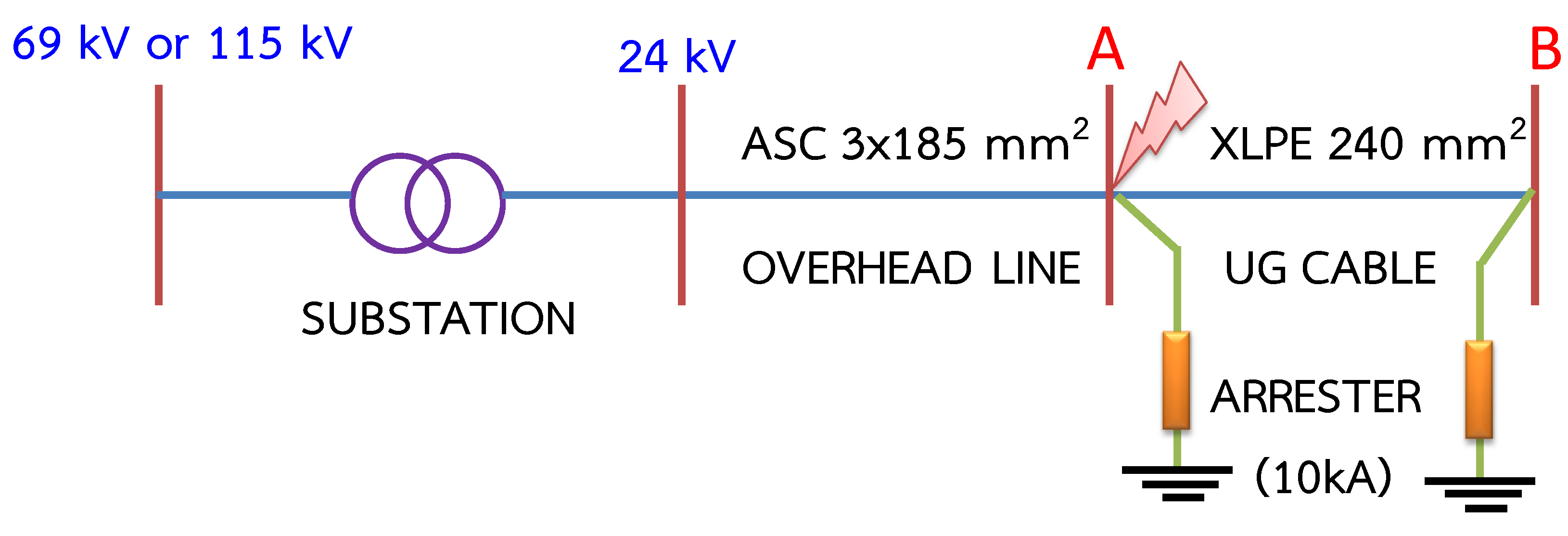
Protection with lightning arrester both at conjunction and the end of underground cables.
Figure 41.
Protection with lightning arrester both at conjunction and the end of underground cables.
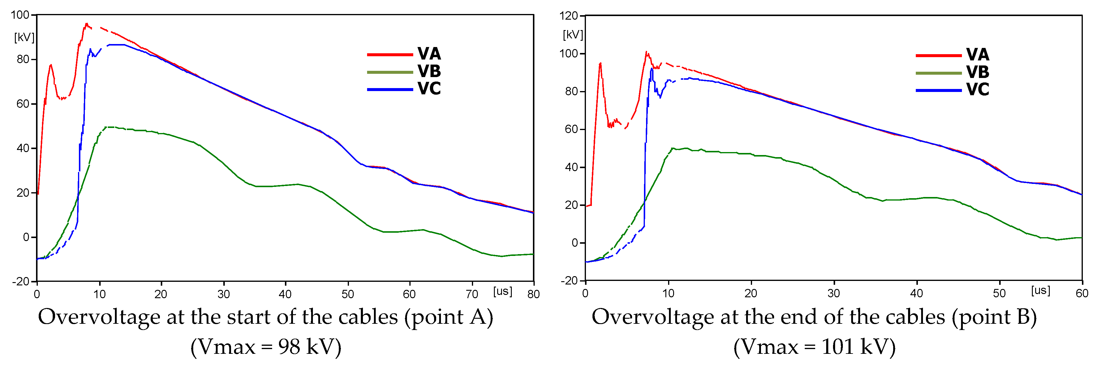
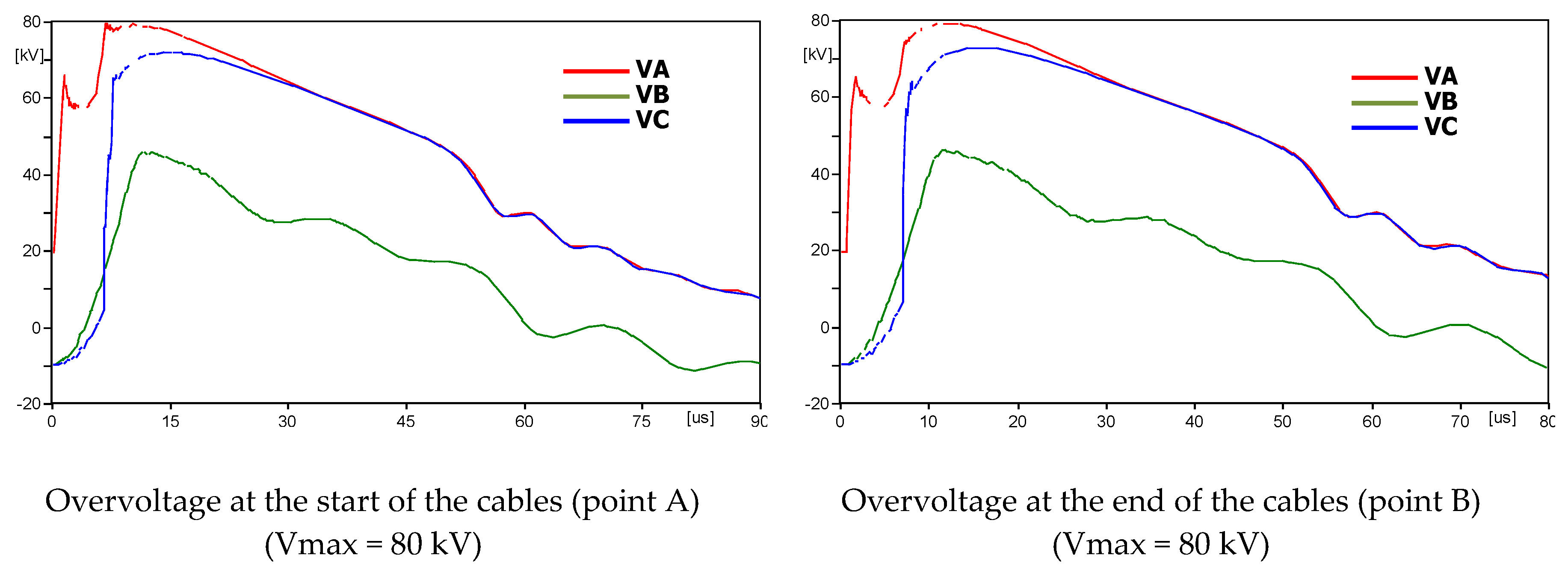
Figure 42.
A 100 m underground cable.
Figure 42.
A 100 m underground cable.
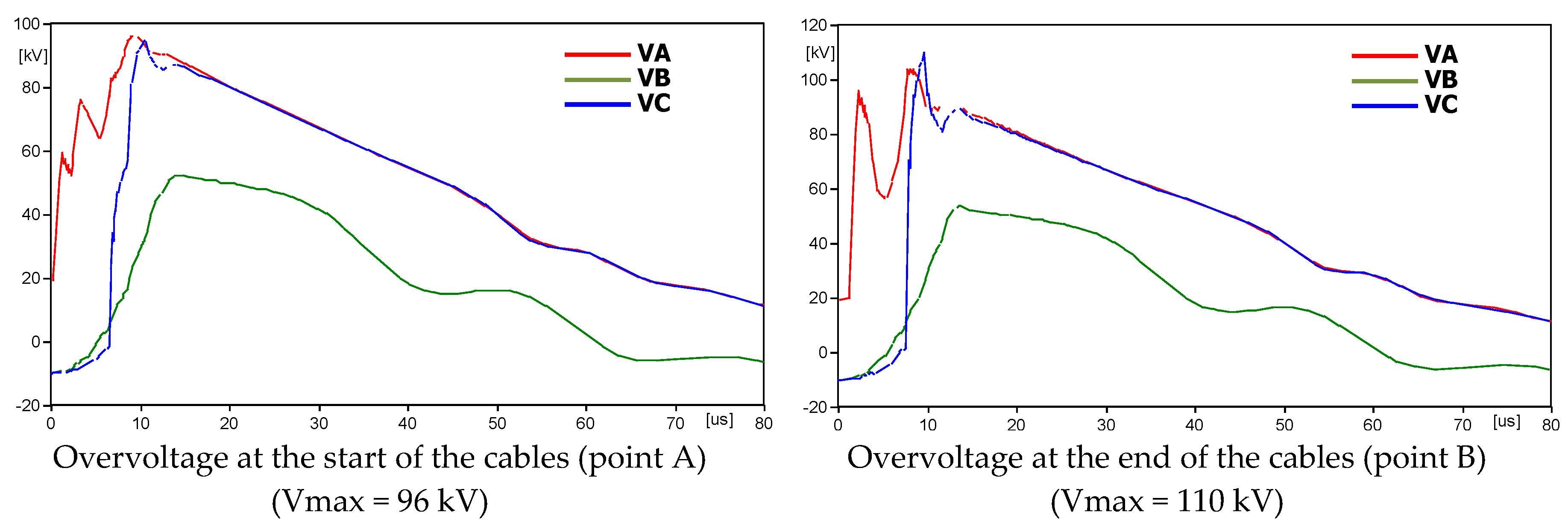
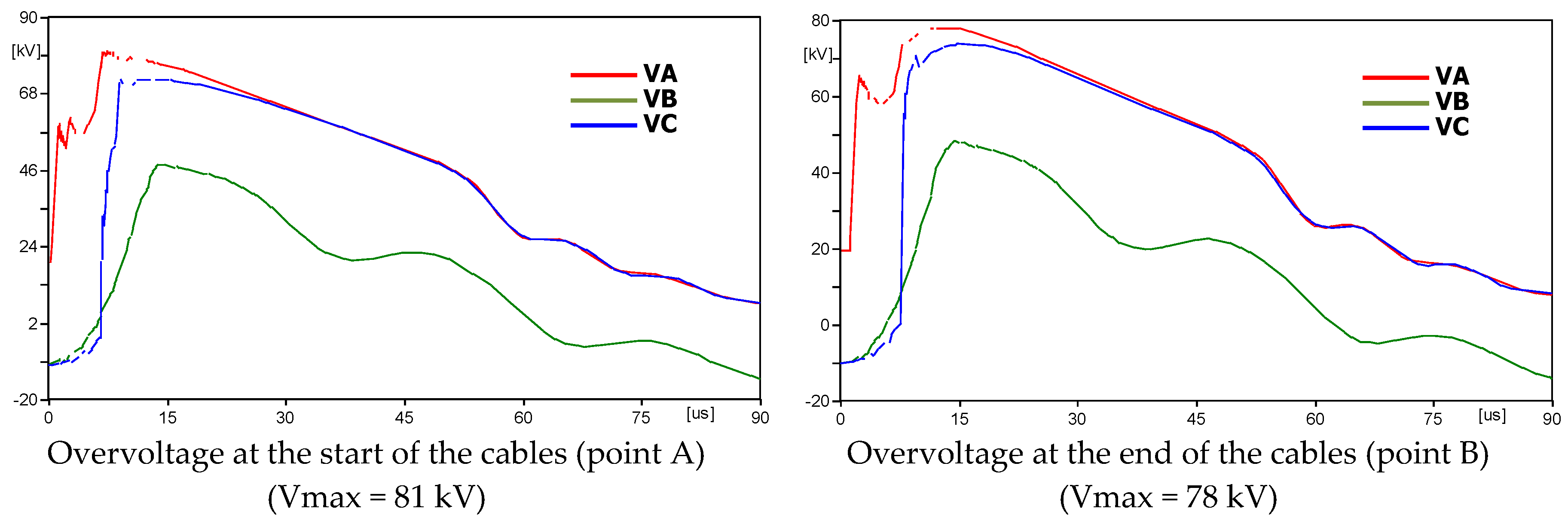
Figure 43.
A 200 m underground cable.
Figure 43.
A 200 m underground cable.
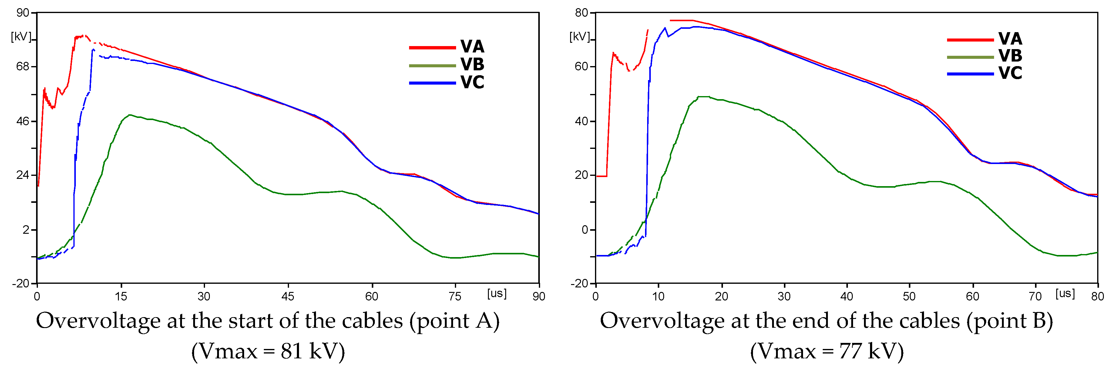
Figure 44.
A 300 m underground cable.
Figure 44.
A 300 m underground cable.
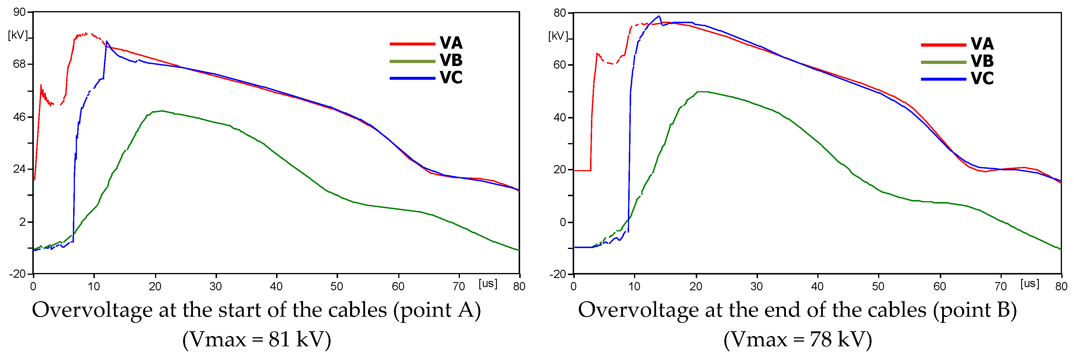
Figure 45.
A 400 m underground cable.
Figure 45.
A 400 m underground cable.
Figure 46.
A 500 m underground cable.
Figure 46.
A 500 m underground cable.
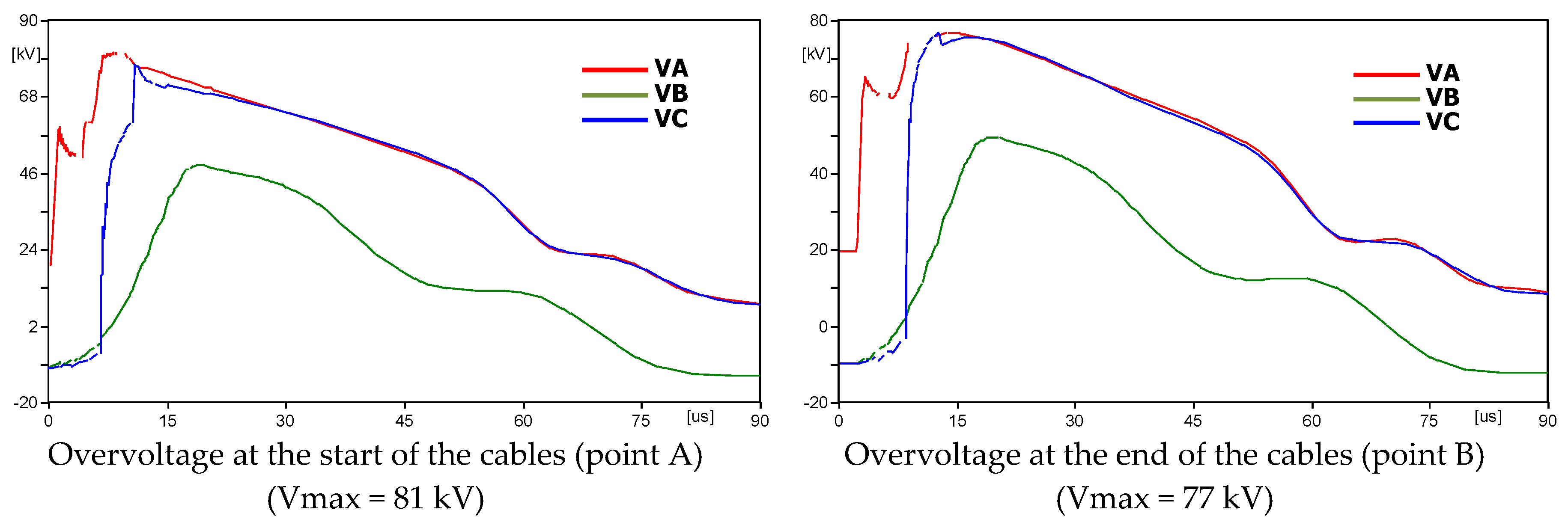
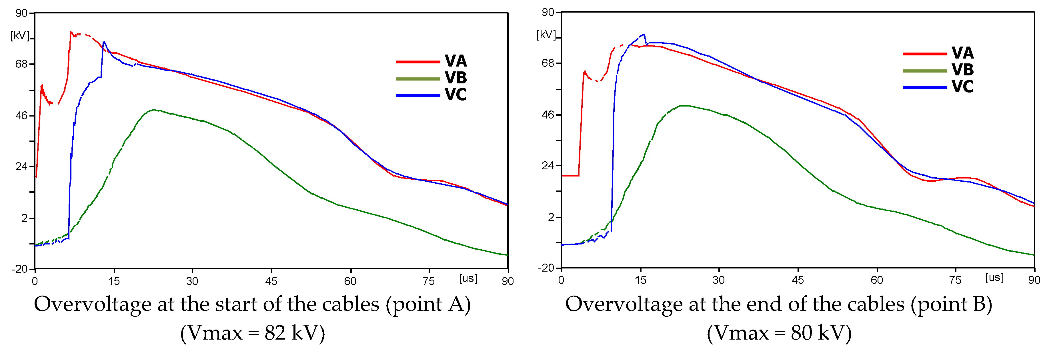
Figure 47.
A 600 m underground cable.
Figure 47.
A 600 m underground cable.
Table 1.
Systems of protection for distribution lines.
Table 1.
Systems of protection for distribution lines.
| Method | Advantages | Disadvantages |
|---|
| Using shielding wire above the cable to intercept the lightning [5] | Easy to install and not expensive | Relies on designs with low ground resistance |
| Adding vertical rods [12] | Not expensive | Hard to install, a slight decrease in ground resistance |
| Install surge arrester [14,17] | The best option for reducing the back-flashover and outage rate | Expensive, arrester may fail in cases with low ground resistance |
|
Using the low-resistivity material covering the grounding conductor [18]
|
Decrease the power-frequency grounding resistance
| A slight decrease in ground resistance |
| Using a composite transmission line tower by double grounding the conductor system [25] | Flashover will not happen for negative or positive injected lightning current | Hard to install, expensive |
Table 2.
Comparison of this study with similar work.
Table 2.
Comparison of this study with similar work.
| This Study | Similar Work |
|---|
This paper evaluates the effect of a lightning strike directly to the 24 kV distribution lines in Thailand. The analysis shows that:- (1).
When surge arresters are not installed, the voltage across the insulator at the end of the line is approximately 1.4 times that in the middle of the line; - (2).
The ground resistance and grounding distance of the overhead ground wire affect the voltage across the insulator if the overhead ground wire is struck; - (3).
When surge arresters are installed, a shorter grounding distance of the overhead ground wire and a lower ground resistance are not always desirable; this is because they reduce the back-flashover rate and the voltage across the insulator if lightning strikes the overhead ground wire. However, lightning strikes to the phase conductor result in high arrester energy and the possibility that the arrester will fail; - (4).
The tail time of the lightning waveform is a significant variable when considering the energy absorbed by the arrester, whereas the front time is important for the voltage across the insulator; - (5).
In the case where lightning directly strikes the connecting point between the overhead lines and the underground cables, the distribution line system is protected only by the lightning arrester at the connection point. The overvoltage the connection point is lower than the basic impulse level at 24 kV of 125 kV, but the overvoltage at the end of the cable is still more than 125 kV when the cable is longer than 400 m. When the distribution line system is protected by lightning arrester at both the connection point and the end of the cable, overvoltage throughout the cable is lower than the critical flashover of insulation. This method is the best way to reduce the failure rate of underground cables and equipment that are connected to the distribution line system.
| Reference [17] describes the effect of overhead ground wire and the influence of the installation location of the surge protection device on energy absorption, due to a direct lightning strike on the 6.6 kV distribution line. The analysis shows that:- (1).
The overhead ground is more effective in preventing damage to the surge arrester than increasing the surge arrester’s ability to withstand damage; - (2).
The energy absorption without an overhead ground wire is about 3–5 times larger than that with one; - (3).
In case lightning strikes directly to the overhead ground, the energy absorption of the surge protection device installed at the end of the line will be increased to approximately 2.3 times that of the arresters installed at the middle of the line; - (4).
Grčić et al. [ 7] deal with lightning overvoltage in a mixture of overhead line and underground cable distribution network supplying an industrial consumer with a 35 kV distribution line; - (5).
The open end of the cable was considered in simulations as the most unfavorable, and optimal overvoltage protection was selected, including the installation of surge arresters at both cable ends, which significantly improved the overvoltage protection of the cable.
|
Table 3.
Arrester characteristics.
Table 3.
Arrester characteristics.
| Characteristics | Data |
|---|
| Maximum continuous operating voltage (kVrms) | 17 |
| Nominal voltage (kV) | 21 |
| Energy absorption (kJ/kV) | 1.15 |
| Voltage (kV) for 5 kA, 8/20 μs | 70 |
| No. of parallel columns of discs | 1 |
| Length of arrester column (m) | 0.315 |
Table 4.
Parameters used for the design.
Table 4.
Parameters used for the design.
| Description | Data |
|---|
| Lightning current | Peak value | 40 kA |
| Time-to-half value | 77.5 μs |
| Time-to-crest value | = 4.12 μs |
| Conductor (single) | Outside diameter | 16 mm |
| Direct current resistance | 0.2 Ω/km |
| Overhead ground wire | Outside diameter | 7.93 mm |
| Direct current resistance | 4.7 Ω/km |
| External ground wire | Outside diameter | 7.93 mm |
| Impedance (Zt) | 408 Ω |
| Speed of lightning wave | 300 m/μs |
| Concrete pole | Span of pole | 40 m |
| Height | 12 m |
| Single ground rod | Diameter of ground rod | 16 mm |
| Length of ground rod | 2.4 m |
| Ground resistance (R) | 1–50 Ω |
Table 5.
Conductor size of the 24 kV XLPE underground cable.
Table 5.
Conductor size of the 24 kV XLPE underground cable.
| Size (mm2) | 70 | 240 | 400 |
|---|
| Conductor diameter (mm) | 9.73 ± 1% | 18.47 ± 1% | 23.39 ± 1% |
| Diameter over insulator (mm) | 21.7–23.9 | 30.5–33.4 | 35.4–38.9 |
| Overall diameter (mm) | 28.0–30.0 | 39.7–42.4 | 44.5–48.0 |
Table 6.
Maximum overvoltage (kV) at points A and B, where the current of the lightning strike to point A is 40 kA.
Table 6.
Maximum overvoltage (kV) at points A and B, where the current of the lightning strike to point A is 40 kA.
| Length of Underground Cables |
|---|
| 100 m | 200 m | 300 m | 400 m | 500 m | 600 m |
|---|
| Point A | Point B | Point A | Point B | Point A | Point B | Point A | Point B | Point A | Point B | Point A | Point B |
| 259 | 274 | 231 | 246 | 222 | 255 | 204 | 250 | 195 | 255 | 189 | 240 |
Table 7.
Maximum overvoltage (kV) at point A and B, where the current of the lightning strike to point A is 40 kA.
Table 7.
Maximum overvoltage (kV) at point A and B, where the current of the lightning strike to point A is 40 kA.
| Length of Underground Cables |
|---|
| 100 m | 200 m | 300 m | 400 m | 500 m | 600 m |
|---|
| Point A | Point B | Point A | Point B | Point A | Point B | Point A | Point B | Point A | Point B | Point A | Point B |
| 96 | 101 | 96 | 110 | 98 | 120 | 98 | 126 | 98 | 130 | 98 | 132 |
Table 8.
Maximum overvoltage (kV) at point A and B, where the current of the lightning strike to point A is 40 kA.
Table 8.
Maximum overvoltage (kV) at point A and B, where the current of the lightning strike to point A is 40 kA.
| Length of Underground Cables |
|---|
| 100 m | 200 m | 300 m | 400 m | 500 m | 600 m |
|---|
| Point A | Point B | Point A | Point B | Point A | Point B | Point A | Point B | Point A | Point B | Point A | Point B |
| 80 | 80 | 81 | 78 | 81 | 77 | 81 | 77 | 81 | 78 | 82 | 80 |


