1. Introduction
Precast RC structures have drawn great attention for their strong points such as fast construction, high quality, and low environmental impact [
1]. Connections between precast components are crucial for the integrity of precast structures under seismic loads [
2]. Grout sleeves are the most common choice for longitudinal reinforcement connection of precast columns for frame structures [
3]. However, the method requires high accuracy to assemble the precast components successfully and there is no effective way to check the grouting quality. In addition, beam-column joints are the vital part of the precast earthquake-resistant frames [
4,
5]. To meet the requirement of anchorage demands of reinforcements of precast beams and the shear strength of joint zone under seismic actions, the joint reinforcement details of traditional precast frame structures are often complex [
6,
7]. Especially in high earthquake intensity areas, numerous transverse as well as longitudinal reinforcements are required in the joint zone, which will bring great construction difficulty and deficiency [
8].
In order to improve the strength of beam-column joints, FRCC and FRP rehabilitation methods are used and studied. Vecchio et al. [
9] proposed a beam-column joint with a FRCC jacketing in the joint zone area. The seismic performance of the proposed joints was studied by cyclic loads. The shear strength and energy dissipation were promoted effectively through the thin jacketing. CFRP sheets and CFRP ropes were used to strengthen the joint strength in the literature [
10]. Similar studies and conclusions were carried out by various retrofit methods, including additional bars, steel plates, and angles [
11,
12,
13,
14]. It was inspiring to see that such retrofit methods could improve the seismic performance of those old-style RC beam column joints effectively. However, for the precast RC structures which were designed with modern codes, it could be troublesome to use the retrofit methods rather than some new construction material to improve the seismic performance from the very beginning.
Pretensioned prestressed beams have smaller section size than non-prestressed beams. With the use of pretensioned strands, precast pretensioned prestressed beams can carry the live loads in construction stage so that the bracing needed for precast beam construction can be omitted, leading to a lower cost economically [
15,
16]. However, the development length of pretensioned strands in the joint zone is too long to satisfy. Taking C50 concrete as an example, the anchorage length of typical pretensioned strands is 119 times of the diameter of the strands, that is, 1.8 m for strands with a diameter of 15.2 mm [
17].
Ultra-high-performance concrete (UHPC) is an efficient material with the advantages of ultra-high strength and excellent bond strength [
18]. With the use of UHPC in the joint zone, the connection details of precast beam-column joints can be simplified and improved [
19,
20]. The amounts of transverse reinforcements in the joint zone can be greatly reduced due to the high strength of UHPC. Moreover, the high bond strength between UHPC and rebars as well as strands can greatly shorten the anchorage length and lap-spliced length of reinforcement [
21,
22].
Extensive investigations have been carried out on the bond strength of UHPC and rebars [
23,
24,
25,
26,
27], mechanical or seismic behavior of precast beams and columns using UHPC for connections. According to the test results, the bond strength between UHPC and rebars was more than 20 MPa and the anchoring length of the straight steel reinforcing bar was 8 to 12 times the rebar diameter [
28,
29]. Meanwhile, the bond strength was 7 to 12 MPa for prestress strands with diameters ranging from 12.7 mm to 21.8 mm. The development length of strands in UHPC have been suggested as 40 or 42 times the strands diameter by different researchers [
30,
31]. Maya [
32] and Graybeal [
33] carried out two full-scale girder tests using lap-spliced strands embedded in UHPC for connection. Approximately 90% of the design ultimate flexural capacity were reached with a strand splice length of 50 times the strands diameter. Peng et al. [
34] carried out cyclic-loading tests on six precast columns with lap-spliced connection using UHPC. The lap length of the rebars varied from 10 to 30 times the rebar diameter. The test results showed that with a lap length of 10 times the rebar length, the precast columns were able to achieve the comparable seismic performance of monolithic ones in terms of bearing strength and ductility. Wang et al. [
35] conducted cyclic tests on a precast bridge column with lap-spliced connection using UHPC and it was concluded that a lap length of 10 times the rebar diameter was enough for rebars with a diameter of 32 mm to exhibit similar seismic performance of the corresponding monolithic RC column.
On the other hand, few investigations have been focused on the seismic performance of beam-column joint using UHPC in the joint zone. Wang et al. [
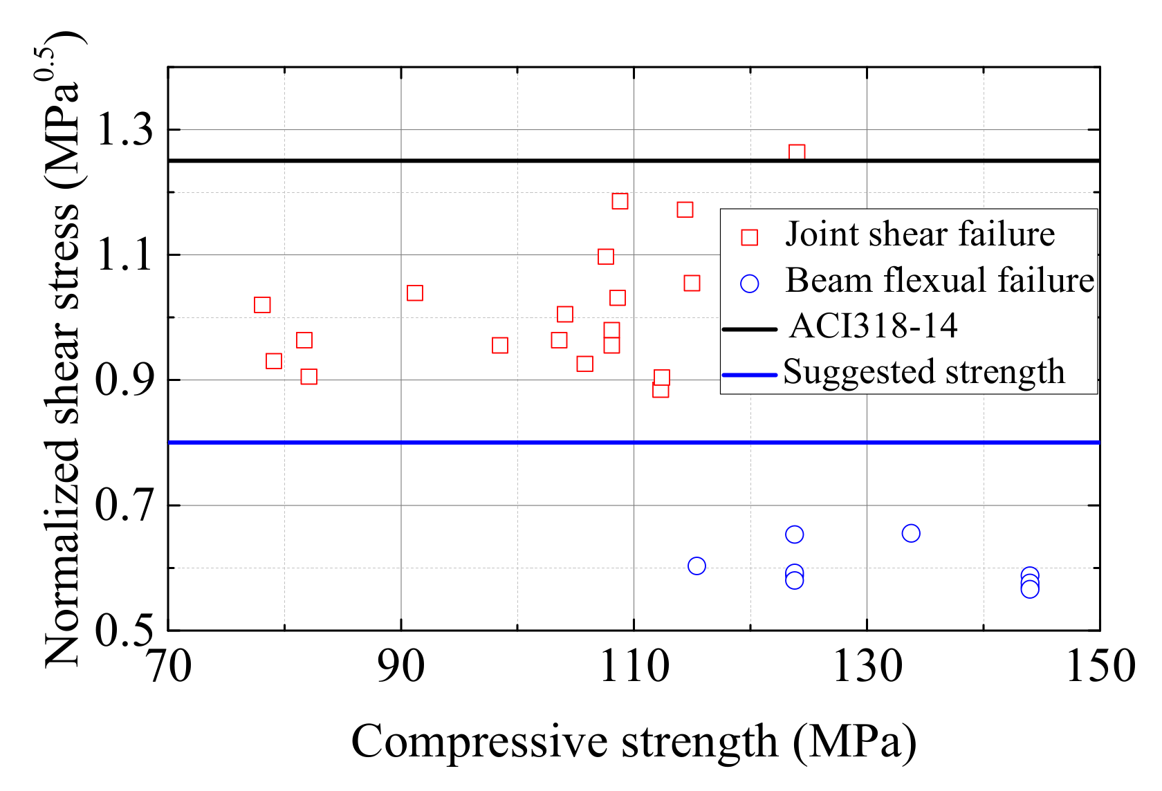
36] carried out cyclic tests on five exterior and four interior monolithic UHPC beam-column joints and the shear strength of the joint zone were studied. The parameters studied were the axial force, stirrup ratio, and joint type. The test results showed that UHPC specimens exhibited excellent seismic performance. However, all the joints were monolithic UHPC beam-column joints and the rebars were passing through the joint zone continuously. The sufficient anchorage length of a rebar in the UHPC joint zone could not be tested by their experiments. Zhang et al. [
37] conducted cyclic tests on four interior precast UHPC/RC composite beam-column joints. The anchorage method of beam bottom longitudinal rebars and the stirrup ratio of the joint zone were set as variables to study the seismic performance of the UHPC joints. The anchorage length of straight or headed bars of beams were suggested as 16 times or 8.1 times the rebar dimeter, respectively. Yet, the connection of column rebars was not focused on in Zhang’s study. The column rebars were passing through the joint zone continuously so that the lap-spliced connection using UHPC was not validated in the paper. Ma et al. [
38] tested five precast beam-column connections with lap-spliced bars in UHPC. The column rebars were lap-spliced in UHPC joints and the lap length was 15 times the rebar diameter. The beam rebars were anchored in UHPC joints and the anchorage length was 10 times the rebar diameter with a tail extension length of 5 times the rebar diameter. The shear strength of UHPC joints were investigated. Nevertheless, the precast beams were non-prestressed specimens only. It was widely known that the cross-sections of prestressed beams and ordinary beams were different. In general, the ratio of beam depth to beam width of prestressed beams was larger than that of ordinary beams, which might cause different stiffness ratios of beam to column. In addition, the damping ratio of prestressed frames were smaller than that of ordinary concrete frames, leading to a larger earthquake action for prestressed members. Xue et al. [
39] carried out the cyclic tests of two beam-column interior joints and two exterior joints to study the seismic performance of precast joints using UHPC-based connections. The UHPC was used for the connections of beam and column rebars. The anchorage and lap-spliced length of beam and column rebars were both 15 times that of the rebar diameters. The cast-in-place concrete included UHPC part and ordinary concrete part. The seismic performance of precast joints was compared to that of monolithic joints under high axial forces. The test results showed that precast members reached similar bearing strength to monolithic ones, indicating that UHPC-based connections could take full use of the strength of beam and column rebars. Yet, only one interior and one exterior beam-column joint were tested, respectively. The limited number of specimens deterred further investigations.
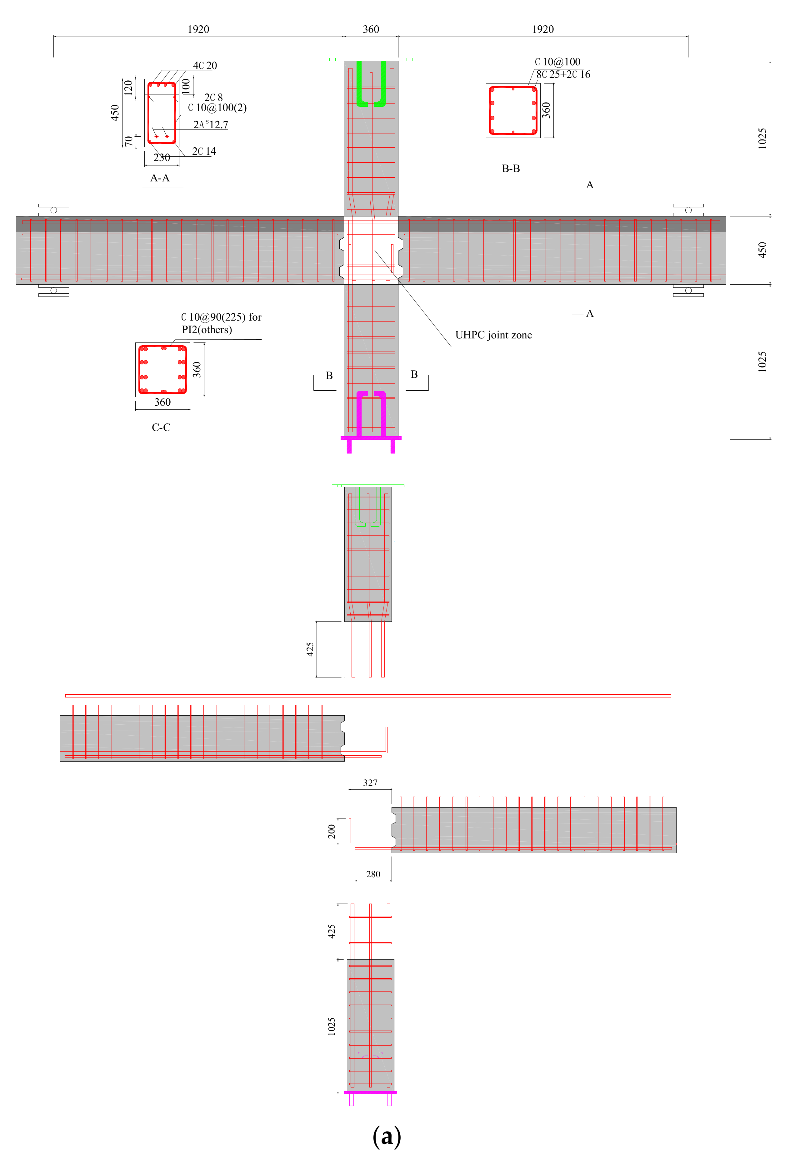
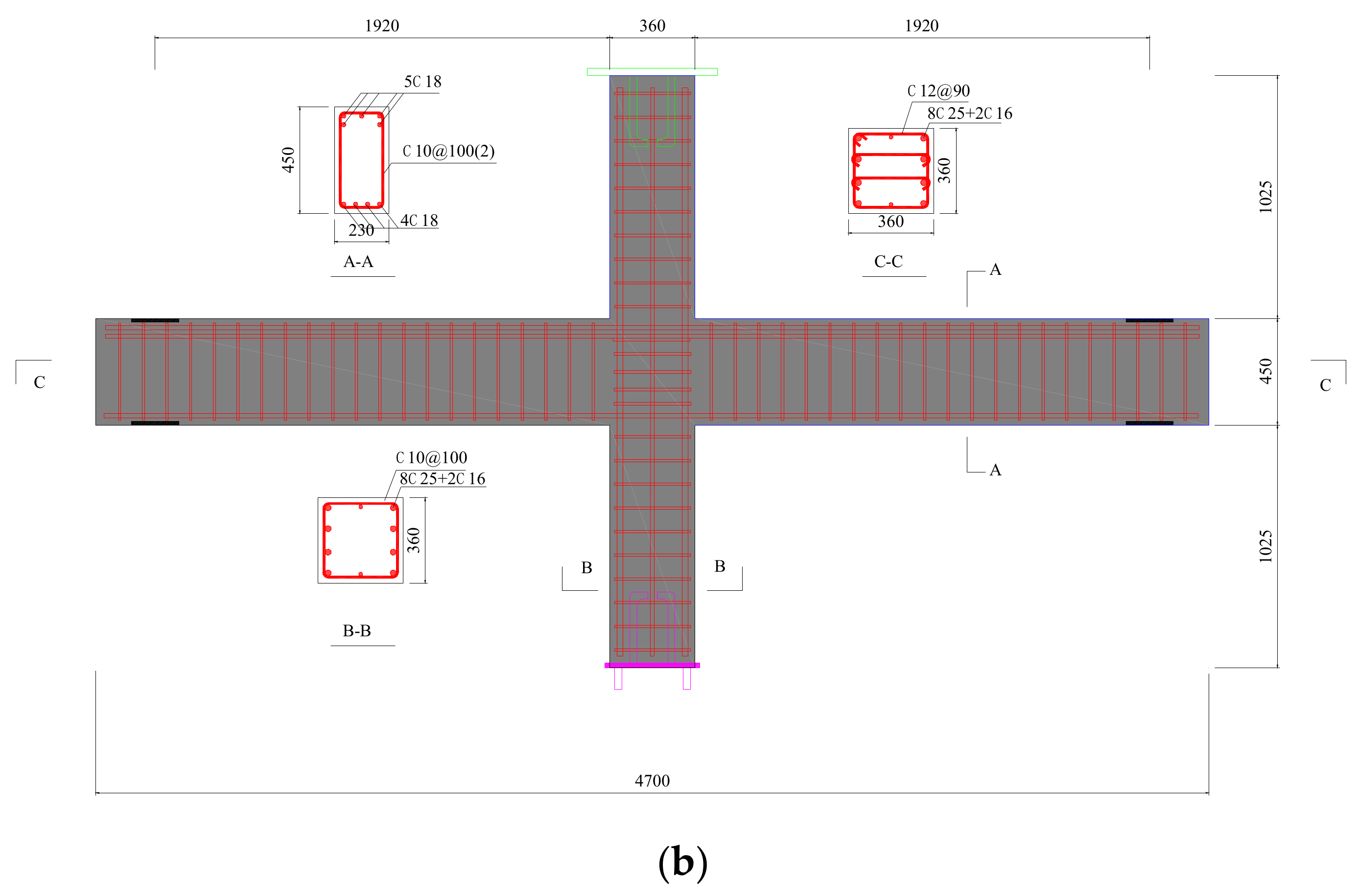
After the review of studies mentioned above, the remaining problems are as follows. The anchorage length of strands in UHPC can be shortened; so, theoretically, it is feasible to use UHPC to connect the pretensioned beams and precast columns in the joint zone and, herein, the advantages of prestressed members and precast systems are combined together. However, the investigation on the application of UHPC in the joint zone for precast prestressed beam-column joints is not found by the authors. There are significant differences between prestressed members and ordinary members in section size ratios. In addition, the contribution of pretensioned prestressed strands at the beam end in seismic actions was unclear. Herein, a new type of precast frame is proposed in the study. The UHPC is used in the joint zone for connection. The precast beams contain prestressed strands and protruding longitudinal rebars. Both strands and rebars are to be anchored in UHPC. The column longitudinal rebars are lap-spliced in the UHPC joint zone so that the connections of precast beams and columns can be placed within the joint zone by UHPC and the advantages of prestressed members are introduced into the new joints at the same time.
In this study, six precast interior beam-column joints and one monolithic joint were tested on cyclic loads to study the seismic performance. The beams were precast beams with pretensioned strands at the bottom and the columns were precast columns protruding the longitudinal rebars. UHPC were used in the joint zone for fabricating the precast beams and columns together. The effects of axial force, compressive strength of UHPC, stirrup ratios, and bond behavior of rebars in UHPC on the seismic performance of the new joints were thoroughly studied. Moreover, design recommendations are given based on the test results.
3. Results
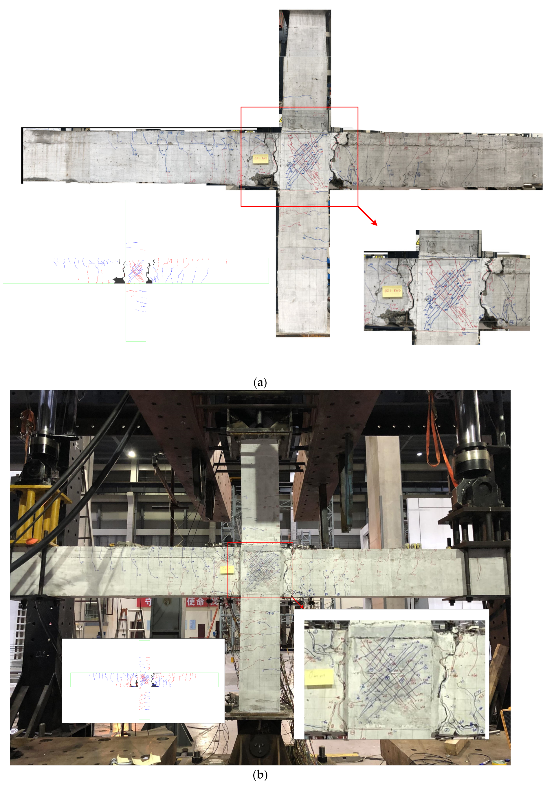
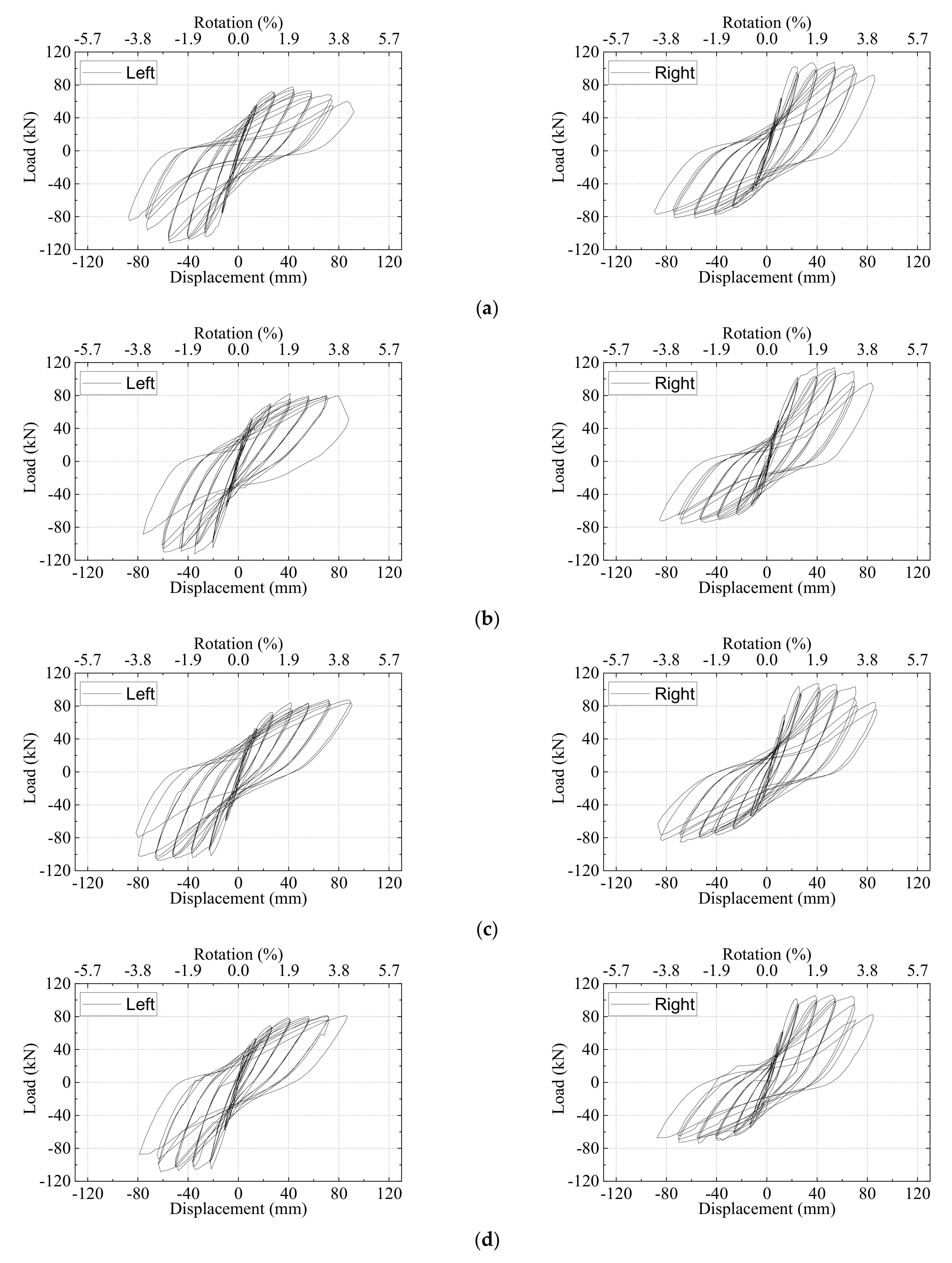
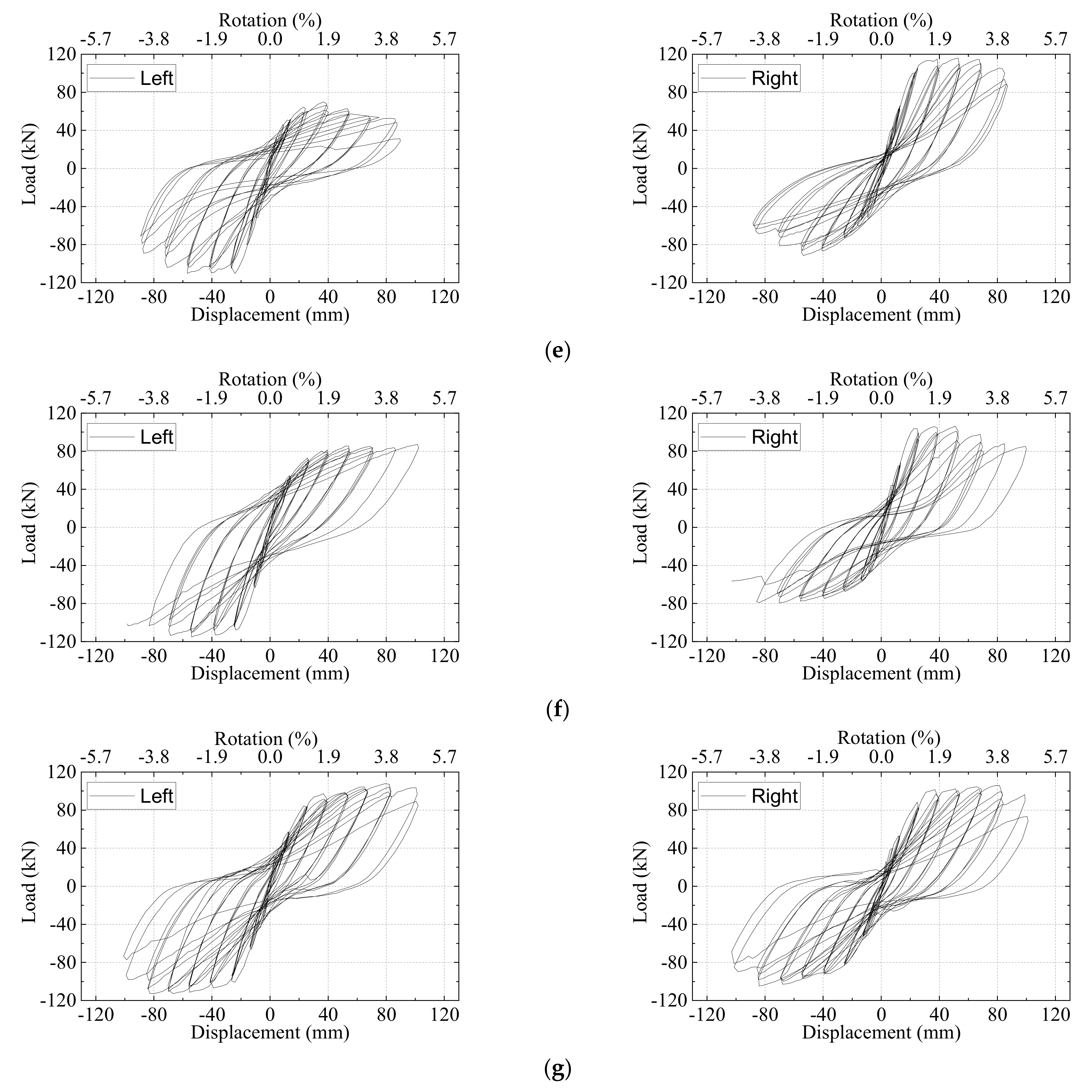
The whole process of loading could be roughly divided into four stages, that is, (a) cracking stage; (b) yielding stage; (c) peak stage; (d) ultimate stage. The direction is defined as positive for discussion convenience when the two actuators move oppositely causing the joint to rotate clockwise.
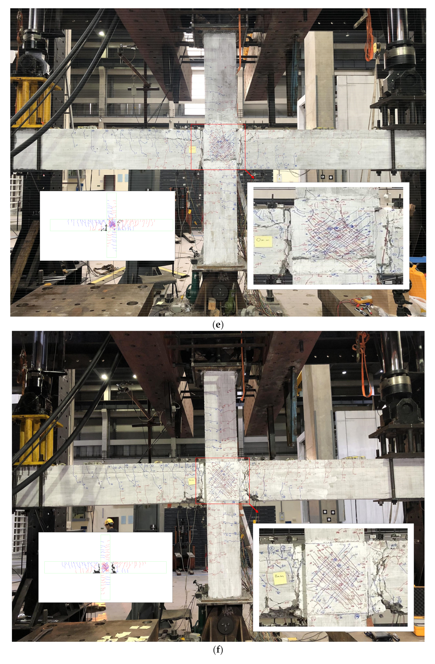
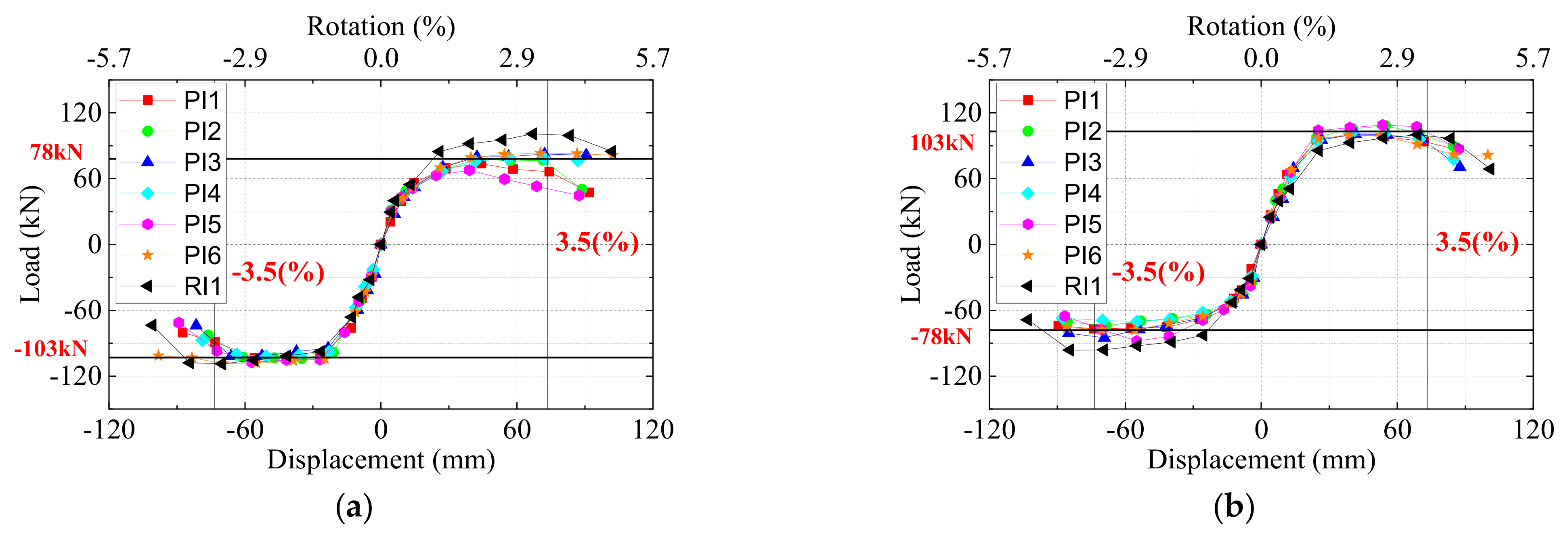
(a) Take specimen PI4 for example, the first two flexural fine cracks were found at the right beam end near the column and at the left beam end near the interface of the precast beam key groove and cast-in-place UHPC at the displacement of −2 mm. The first crack showed up in the UHPC joint area at the displacement of +10 mm. The width was less than 0.02 mm. (b) The right and left beam longitudinal rebars yielded at the load of +91.10 kN and +71.35 kN, respectively, in the positive direction according to the equivalent elastoplastic energy method suggested by Park [
41]. The corresponding yield displacements were +24.56 mm and +28.97 mm, respectively. At the yield stage, the crack between the precast beam and UHPC joint became quite thick with a width of 1.4 mm and 2.2 mm. The main flexural crack went along the edge of key grooves. The UHPC in the joint area was cured in the natural environment maintenance condition. This may cause large shrinkage of UHPC which led to the relatively weaker performance at the interface. The crack widths in the UHPC joint area were quite small with the maximum value of 0.06 mm, which proved the excellent crack control performance of UHPC. It should be mentioned that the number of cracks at the bottom part of the beam was much smaller than at the top part. The reason could be that the bond strength between concrete and rebars was higher than that between concrete and strands [
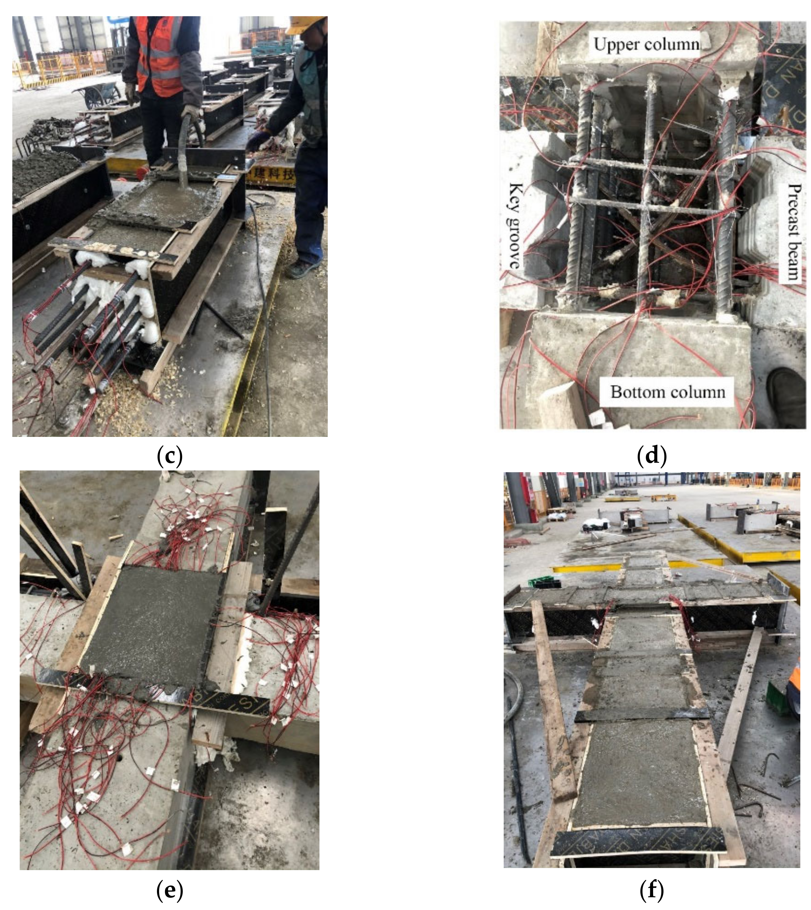
42]. The tensile stress could be well transferred and cracks were distributed over a longer distance. Diagonal fine cracks with close distance appeared in the UHPC joints area and the maximum crack width was 0.08 mm. (c) As the loads increased, flexural cracks within the plastic hinge zone of beams grew and some of them turned into flexural-shear cracks. The widths of the main cracks at both sides of the interfaces between precast beams and UHPC joint were wider. The maximum loads reached 100.38 kN and 78.86 kN for the right and left beams. The maximum width of cracks in the UHPC joint was 0.1 mm only. (d) As the displacement went up, a typical beam flexural failure occurred. With the cover concrete in the plastic hinge zone spalling and rebars exposing, the loads decreased to 85% of the peak loads and the test was stopped. During the test, the damage of UHPC joint was minor and the design target of strong-joint and weak-members was achieved successfully. The failure mode and crack pattern can be seen in
Figure 5d.
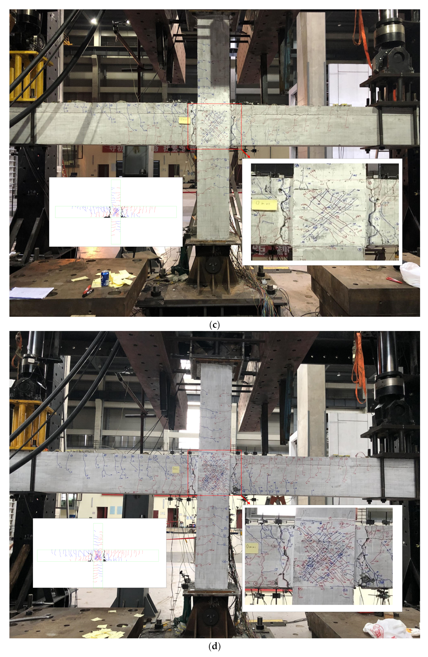
For the other five precast UHPC joint specimens, which are exhibited in
Figure 5, the test behaviors as well as failure modes were similar compared to PI4. The maximum width of diagonal cracks in the UHPC joint zone was 0.15 mm, indicating the damage of the joint zone was minor and all precast UHPC specimens exhibited the beam flexural failure.
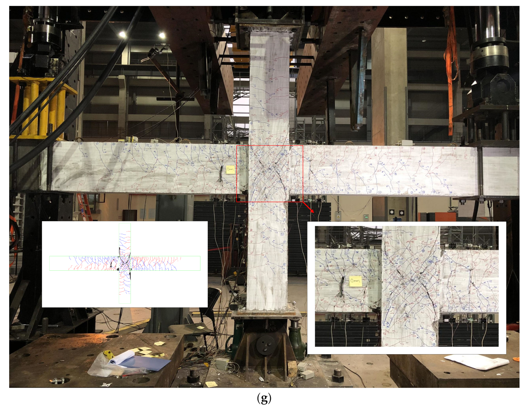
As for the monolithic RC specimen RI1, the crack pattern was different. The distribution of cracks at the beam bottom was broad and the crack number was a lot larger than that in the precast joints as seen in
Figure 5f. This is because the bond performance between concrete and rebars is better than strands. Moreover, the crack pattern in the joint zone was different for specimen RI1. When the displacement reached 75 mm, the evident diagonal crack showed up in the joint zone and the maximum crack width was 1.7 mm. As seen in the right bottom of
Figure 5f, the failure mode of RI1 exhibited a typical joint shear failure after yielding of the beam longitudinal rebars. Even though the reinforcement details in the joint zone followed the requirements of code standards, the strong members–weak joint philosophy was not fully achieved in the test. Nevertheless, the shear failure occurred at the displacement drift ratio of 3.6%, which already exceeded the required value of 2%. Thus, the seismic performance of specimen RI1 was satisfied in some way. Anyhow, the differences of failure modes between UHPC joint and RC joint showed the advantage of the application of UHPC.


