A wide variety of arrangements and utilizations of atmospheric-pressure cold plasmas has currently been reported. Among these, nonthermal atmospheric-pressure jet plasmas have obtained increasing attention as a result of their great merits in application as an analytical tool or as a photonic device [
1,
2], for material modifications [
3,
4,
5,
6], for bacterial inactivations [
7], and for biomedical applications [
8,
9,
10]. Generation of these types of plasma jets was shown to be possible via sinusoidal voltage excitation at various frequencies from the Hz to MHz ranges in previous articles [
11,
12,
13,
14]. These types of jets were characterized by high electron density (
ne up to 10
15 cm
−3), low gas temperature (
Tg near 300 K), and low power consumption. The jet-type plasmas produce plasma flames in open air rather than in restricted discharge electrode gaps. In terms of their applications, therefore, cold atmospheric-pressure jet plasmas provide the valuable practicality of dividing the plasma forming zone from the utilization area and thus accelerating an approach associated with an extensive range of surface chemistry. From the standpoint of economics, utilizing less expensive gases such as nitrogen and air for practical applications of cold atmospheric-pressure jet plasmas may be favorable. For this cause, a specially designed jet plasma device acting with air is investigated. A grounded electrode is utilized to discharge the air jet plasma into atmospheric air. The ground electrode has a 0.7 mm hole. This design reveals several good characteristics, which includes the generation of very high levels of reactive oxygen-related species and extremely lesser power consumption in connection with a compact structure and ease of handling. A striated discharge pattern is made from the air jet plasma at high gas flow rate. A striated discharge pattern is known as a phenomenon of an ordered macroscopic structure that results from a nonlinear interaction. In particular, dielectric barrier discharges have shown such striations in the form of hexagons, spirals, strips, and concentric rings [
15,
16,
17,
18] that are created between two electrodes arranged in reduced gas-pressure. In the present work, the striated discharge patterns are observed along the air plasma jet length at atmospheric-pressure, demonstrating that a series of alternating light and diffuse-style columns along the plasma jet are gradually damped out.
Figure 1 displays an illustration of the device utilized to generate the air plasma jet. The jet plasma system is composed of a dielectric tube, electrodes, and a power supply that runs at high voltages. The alternating voltage source shown in
Figure 1 is a commercial transformer maintained at 20 kHz (maximum voltage of V
rms = 15 kV) and is combined with two electrodes. The stainless steel inner electrode is 1.2 mm in inner diameter with 0.2 mm thickness and 100 mm length. It is wrapped with a quartz tube and a dielectric one with 3.2 mm outer diameter and 80 mm length. The outer ground-electrode is designed with a pencil-type. It is machined for the inner electrode with a dielectric tube to be interpolated. The centrally perforated outer electrode with 0.7 mm hole emits the jet plasma into surrounding ambient air. In the area of plasma production, in addition to being in contact with the external electrode, the end of the dielectric tube protrudes 1 mm as a gap for discharge against the end of the inner electrode. The distance between the tips of the dielectric tube and the internal electrode is adjusted to control the discharge gap.
The jet plasma in the present study is generated from a discharge inside the 1 mm distance. The discharge gas and air enters the device through the inner electrode and is expelled into open air via the discharge zone. The inset in
Figure 1 reveals that when the internal electrode is exposed to air and high voltage power is supplied, a discharge is initiated in the gap between the electrodes. This results in a long jet plasma in length in the order of several centimeters, which is expelled to the ambient air. This non-thermal plasma jet can be applied to the surface treatment of thermally sensitive materials.
Jet plasma generated at 5 lpm (liters per minute) dried-air in the inset of
Figure 1 is ejected at a velocity of around 216 m/s causing an afterglow discharge, which subsequently cools around room temperature. Since the temperature of the air micro-jet plasma shown in
Figure 1 is low, it can be handled by naked hands or scrutinized over human or animal skin without initiating a pathway for conduction. According to the simplest biological equivalent model [
19], the general resistance and capacitance of a human being are about 1 MΩ and 60 pF, respectively. The effective capacitance in the discharge region of
Figure 1 was calculated as approximately 0.018 pF. Therefore, this reactance is 447 MΩ for an applied voltage of 20 kHz. In the worst case (reported in Ref. 11), the total reactance of a human is approximately 133 kΩ for 20 kHz, which is much less than the reactance in the discharge region. Therefore, the voltage drop for a human is approximately 0.53 V. Most of the voltage drop occurs between electrodes. This explains why a human can touch the plasma jet or can be treated without receiving electrical shock.
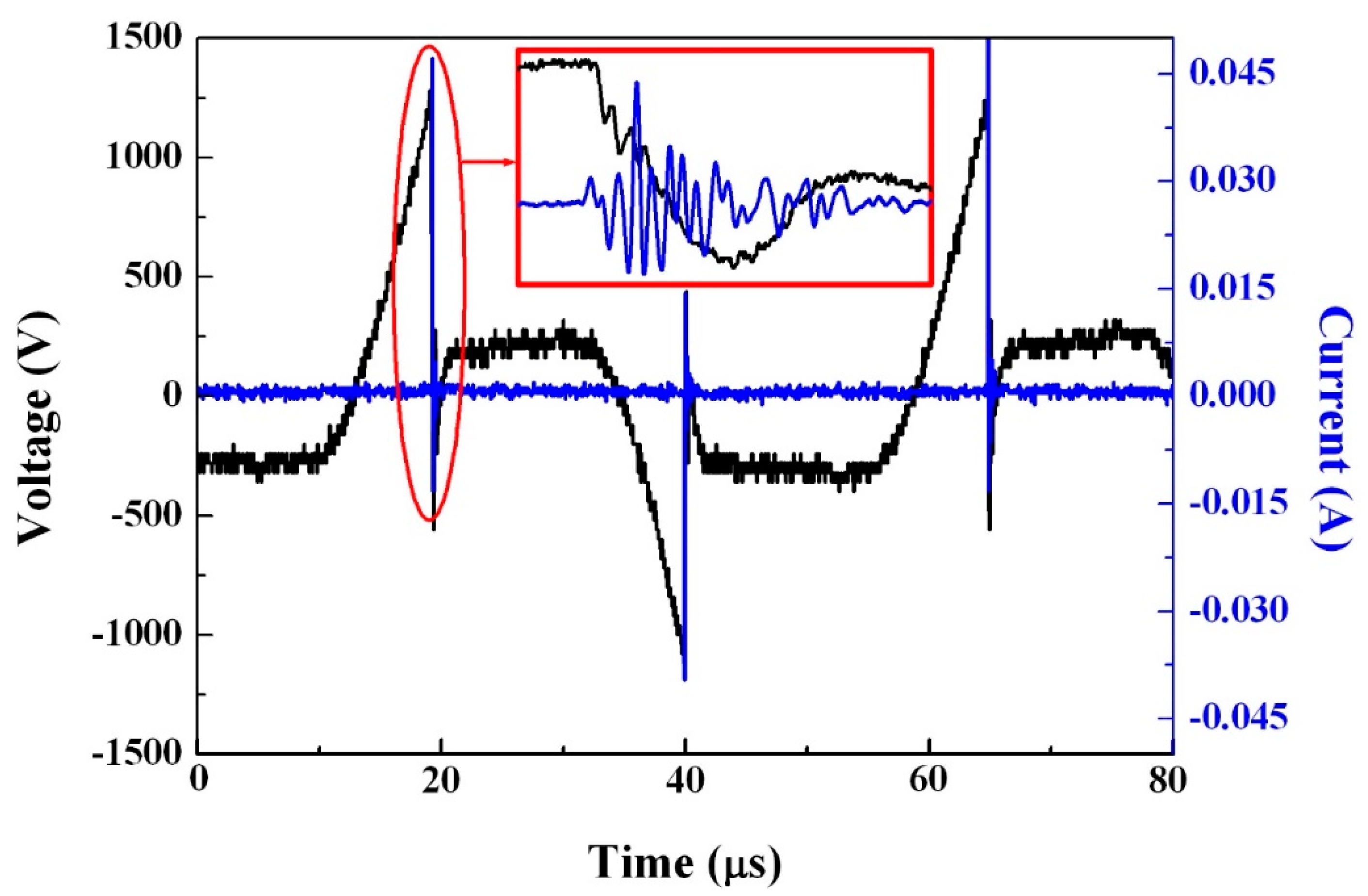
The waveforms of the jet plasma, corresponding to current and voltage, are operated at V
p = 1.25 ± 0.1 kV at an airflow rate of 5 lpm and are displayed in
Figure 2. The measurements of voltage and current were carried out using high-voltage and current probes via an oscilloscope (TDS 201, Tektronix, Beaverton, OR, USA). As shown in
Figure 2, the current waveform resembles the general dielectric barrier discharge (DBD) as it occurs in the form of a sharp current spike for every half cycle. At the intermediate plane that is formed between two electrodes, the mean value of the peak current between two consecutive cycles was recorded as 15 ± 1 mA or 1.6 A/cm
2. The current waveforms of
Figure 2 revealed positive or negative values irrespective of the positive or negative voltage values. This is attributed to the attenuating oscillation of the current signal, which is captured at random by the oscilloscope. The inset in
Figure 2 displays that the total time span of the current oscillation is less than 0.5 µs.
Figure 3 reveals the optical emission lines emitted over wavelengths of 200 to 900 nm, which are used to identify the different excited plasma species occurring in the air jet plasma. The optical emission lines were acquired from the micro-jet plasma at an air-flow of 5 lpm. As shown in
Figure 3, the plasma emission lines comprise excited nitrogen species containing N
2 second and first positive systems at a range of 300–390 nm and 700–950 nm, respectively. Moreover, ionized nitrogen molecules at a range of 390–480 nm [
20], ionized nitrogen at 649 and 661 nm, and atomic nitrogen at 747 nm [
21] were shown in
Figure 3. This clearly shows that very reactive atomic oxygen-species at 777 and 844 nm exist in the plasma jet [
10]. The reactive oxygen and nitrogen species can play a pivotal role in the treatment and modification of various surfaces [
22].
The occurrence of the micro-plasma jet in the experiment was revealed to be sensitive to the airflow rate at a steadily applied voltage (V
p = 1.25 kV). The appearance of the micro-plasma jet for a given flow rate value, as shown in
Figure 4, was imaged by employing a digital camera (Cannon DSLR 400 D, Canon, Ohtaku, Japan) with an exposure time of 15 s. The transformation of the plasma structure from the general glow to striation mode as a function of the rate of airflow is displayed in
Figure 4a–c. The gas ejection speed (
vg) from the 0.7 mm hole at 5 lpm recorded a high value of 216 m/s. Nevertheless, the micro-plasma jet in
Figure 4a shows a diffuse and continuous afterglow. With further increases in the airflow rate to 6 lpm (
vg = 259 m/s), however, a transformation in the diffuse afterglow discharge mode (
Figure 4a) into a multiple plasma glow with discrete bright plasma spots appears, as shown in
Figure 4b. The white arrows in
Figure 4b,c indicate the striations. Striated discharge patterns in the experiment and electrode configuration appeared when a flow rate of 6 lpm was used. As shown in
Figure 4b, it is possible to observe them using the naked eye. The striated plasma emissions gradually damp out with the plasma jet and differs in terms of size, brightness, and distance. With an increment in the gas flow rate to 7 lpm (
vg = 302 m/s), although the image in
Figure 4c is not clear due to the weak intensity of the plasma plume, the distance between striations is longer than it is at 6 lpm as a result of the high gas speed. The gas temperatures of the plasma jets, measured using a thermocouple, as a function of air flow rates and matching with the input power in
Figure 1 are shown in
Figure 4d. The distance from the outer electrode is denoted by the axial position z in
Figure 4d. When the airflows increase from 5 to 7 lpm, the gas temperature at z = 2 mm shows a noticeable decrement to 45 °C. With an air flow of 5 lpm, the plasma jet reaches room temperature for positions higher than 15 mm. Even at the position of z = 10 mm, the gas temperature records a low value of 40 °C. The plasma controlled at 6 lpm of air is ejected at a speed of approximately 259 m/s through the outer electrode, which initially produces a high-pressure afterglow and further cools to near room temperature. Since the plasma jet at 7 lpm of air occurs at a low temperature for z = 8 mm, touching the jet using bare hands or exposing it over human skin fails to create a path for conduction [
23].
The plasma volume generated during each electrical discharge is the discharge space of πr
2d at the tip of the inner electrode, where r is the outer radius of the inner electrode and d = 1 mm is the distance of separation of the inner and outer electrodes. Therefore, the plasma volume generated at each electrical discharge was determined to be 1.54 mm
3. The cross-section S of the hole in the outer electrode is given by S = 0.385 mm
2. The plasma column length L in the plasma jet is obtained from L = πr
2d/S, assuming that the plasma volume generated at each discharge is swept away by the jet. It is estimated to be 4 mm. However, the plasma column length may in fact be longer than 4 mm due to the plasma density trailing. The electrical discharge occurs 40,000 times per second, as shown in
Figure 2. The distance
ζ between the centers of consecutive plasma columns in the plasma jet is expressed as
ζ =
vg/40,000, where
vg is the air speed in the jet. For example, the distance between the plasma columns for the air speed of 216 m/s corresponding to
Figure 4a was determined as
ζ = 5.4 mm, which is slightly longer than the column length L = 4 mm, indicating that the plasma jet may be connected continuously by plasma columns with the plasma density trailing of each column. On the other hand, the distance between the plasma columns for the air speed of 259 m/s corresponding to
Figure 4b was found to be
ζ = 6.5 mm, showing that the plasma columns in the jet may discretely occur. The distance between the plasma columns for the air speed of 302 m/s corresponding to
Figure 4c was found to be
ζ = 7.55 mm, which is far longer than the plasma column length. The plasma column length in the jet can be changed by readjusting the ratio of the discharge space volume to the hole cross-section in the outer electrode, which is a function of the electrode gap distance d, the hole size of the outer electrode, the outer radius of the inner electrode, and the airflow rate. Therefore, a continuous plasma jet can be generated for a specified frequency of the high-power module by readjusting the aforementioned system parameters.
The outer electrode is connected to the ground but is not completely grounded for a variety of reasons. Its voltage was in effect determined to be approximately 50 V. The capacitance of the outer electrode was estimated to be C = 2 × 10
−11 F. The electrical energy stored in the outer electrode, W = (1/2) CV, is discharged through the plasma jet whenever the plasma column passes through the tip of the outer electrode, which initiates an ion acoustic wave [
24,
25]
, where
k is the wavenumber,
K is the Boltzmann constant,
Te is the electron temperature, and
M is the ion mass. It is difficult to estimate the wave speed
without knowing the correct electron temperature. Assuming the electron temperature
Te is 1 eV, the wave speed is expressed as
vs = 1820 m/s. The wavelength shall be close to the density modulation in the jet of approximately 6.5 mm, corresponding to a wavenumber of
k = 9.66/cm. The frequency
f =
ω/2π =
kvs/2π of the ion acoustic wave was calculated to be 280 kHz. For example, an ion acoustic wave initiated at the plasma column leaving the tip of the outer electrode excites again 1/
f second later when this column advances 0.93 mm for the plasma jet in
Figure 4b. The observation in
Figure 4b is nearly 1 ± 0.1 mm, which is slightly longer than 0.93 mm. In addition to experimental measurement errors, the discrepancy between the estimation and the observation may be caused by such factors as an inaccurate estimation of the electron temperature or of the plasma density modulation.
In summary, an air micro-plasma jet device at atmospheric pressure composed of an injection needle and micro-hollow electrode was presented in this study. The plasma jet was as long as 3 cm. Additionally, the presence of striated discharge patterns in the afterglow of micro-plasma in highly dynamic gas flow was reported, presenting a mechanism of striation. The produced micro-plasma jet mainly contains excited nitrogen molecules, ionized nitrogen molecules, ionized nitrogen atoms, and atomic nitrogen as well as highly reactive atomic and molecular oxygen. Moreover, further investigation showed the influence of the airflow rate on the evolution of the afterglow plasma into a striated discharge. The characteristics of the micro-plasma jet indicates that the jet device is likely applicable for treatment of fragile items, delicate biological materials, and dental gums in addition to human skin [
26,
27]. Furthermore, the characteristics of the striated discharge patterns will be useful to comprehend the pattern formation in the micro-plasma jet and will provide helpful information for further development of the micro-plasma jet in future.


