Sizing CMOS Amplifiers by PSO and MOL to Improve DC Operating Point Conditions

 ,
, 
Abstract
:1. Introduction
2. Problem Formulation and Handling of Constraints
Search for the widths () and lengths () of each MOS transistor in a CMOS OTA, such that:
Maximize the GBW product of the OTA,
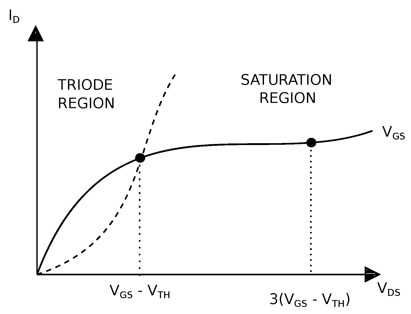
subject to: , for each MOS transistor, and amplifier’s DC gain ≥ 60 dB, phase margin (PM) , common-mode rejection ratio (CMRR) ≥ 60 dB, power supply rejection ratio (PSRR) dB, and slew rate (SR) .
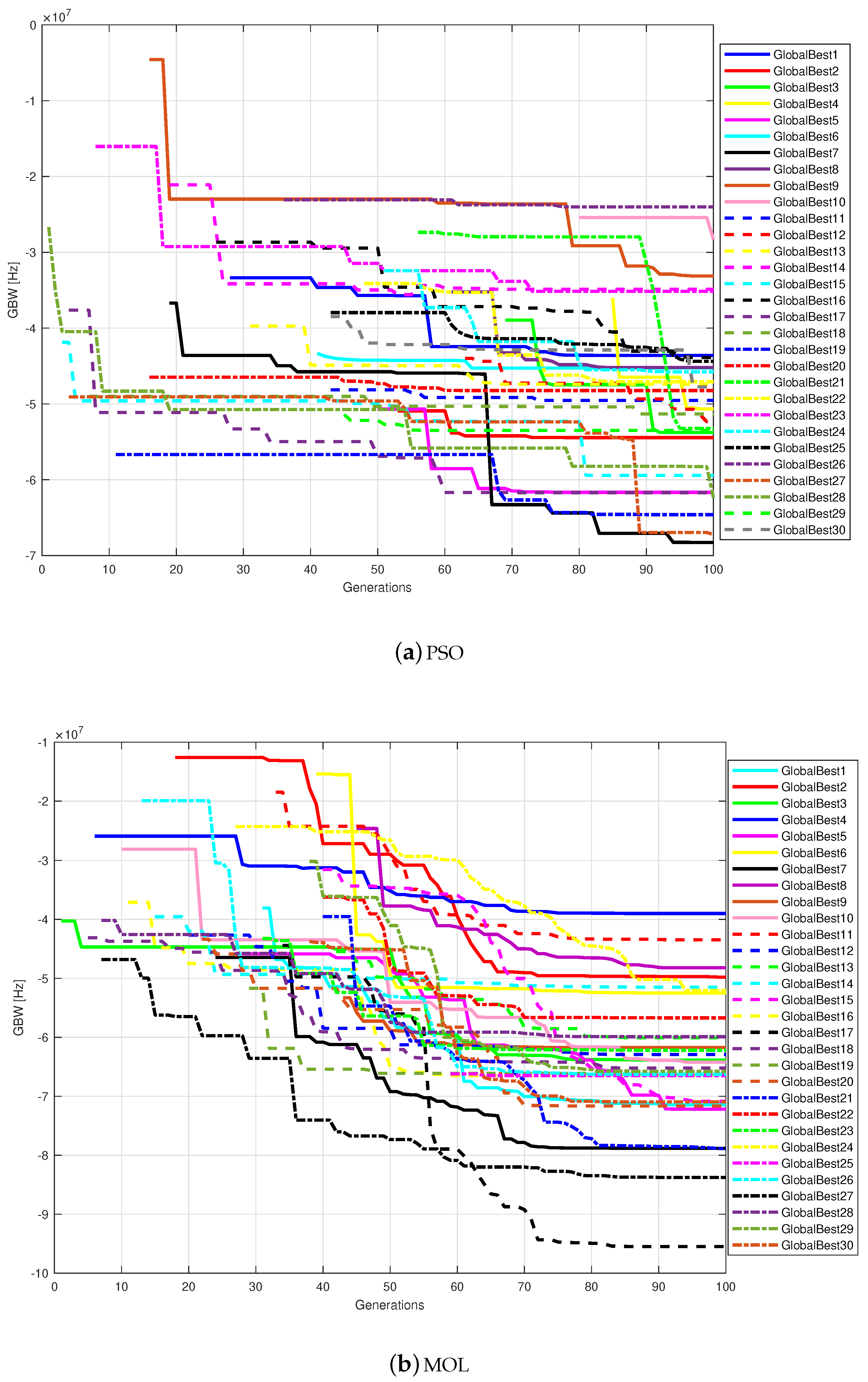
3. PSO and MOL Algorithms
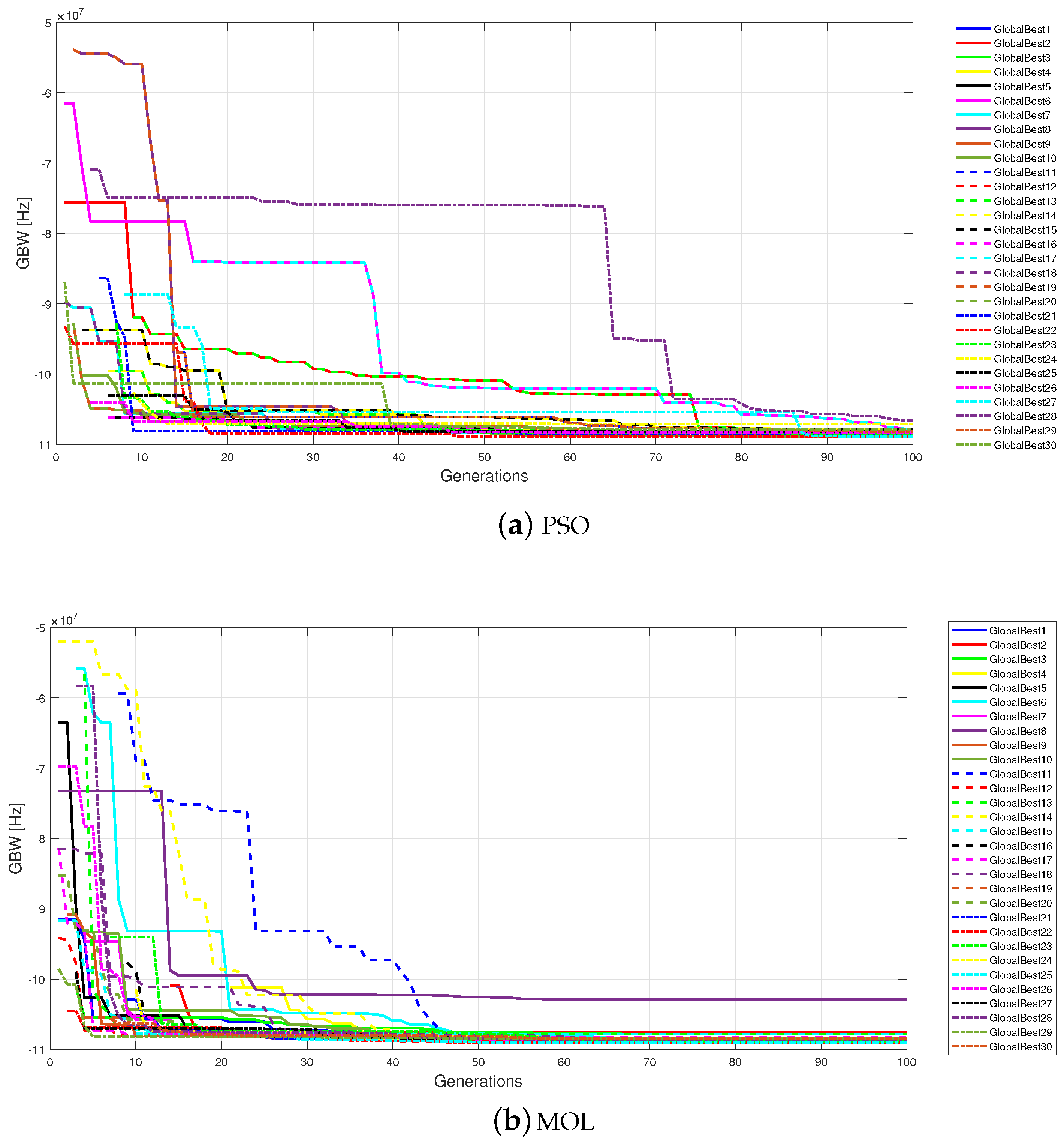
3.1. Particle Swarm Optimization Algorithm
3.2. Many Optimizing Liaisons Algorithm
4. Sizing OTAs by PSO and MOL to Improve DCOP Conditions
| Algorithm 1 PSO |
|
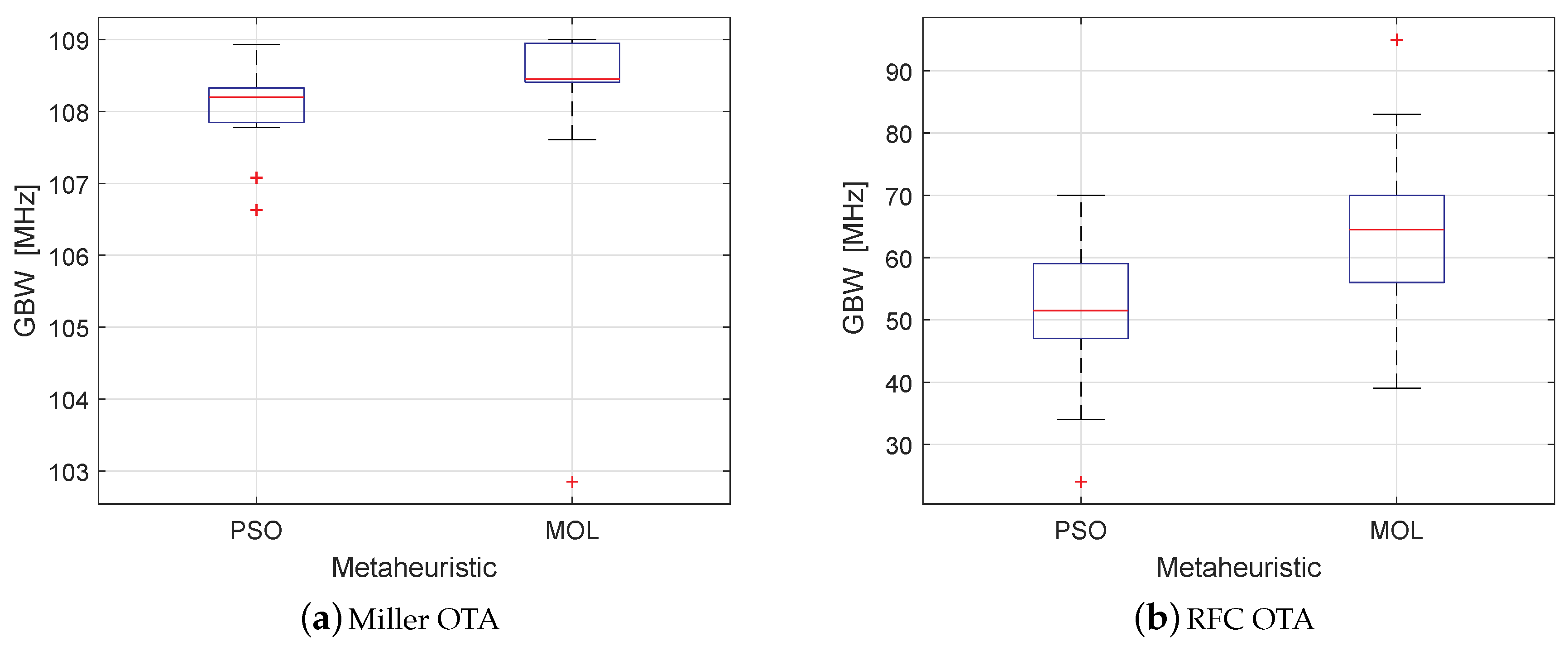
5. Feasible Sized Solutions Provided by PSO and MOL
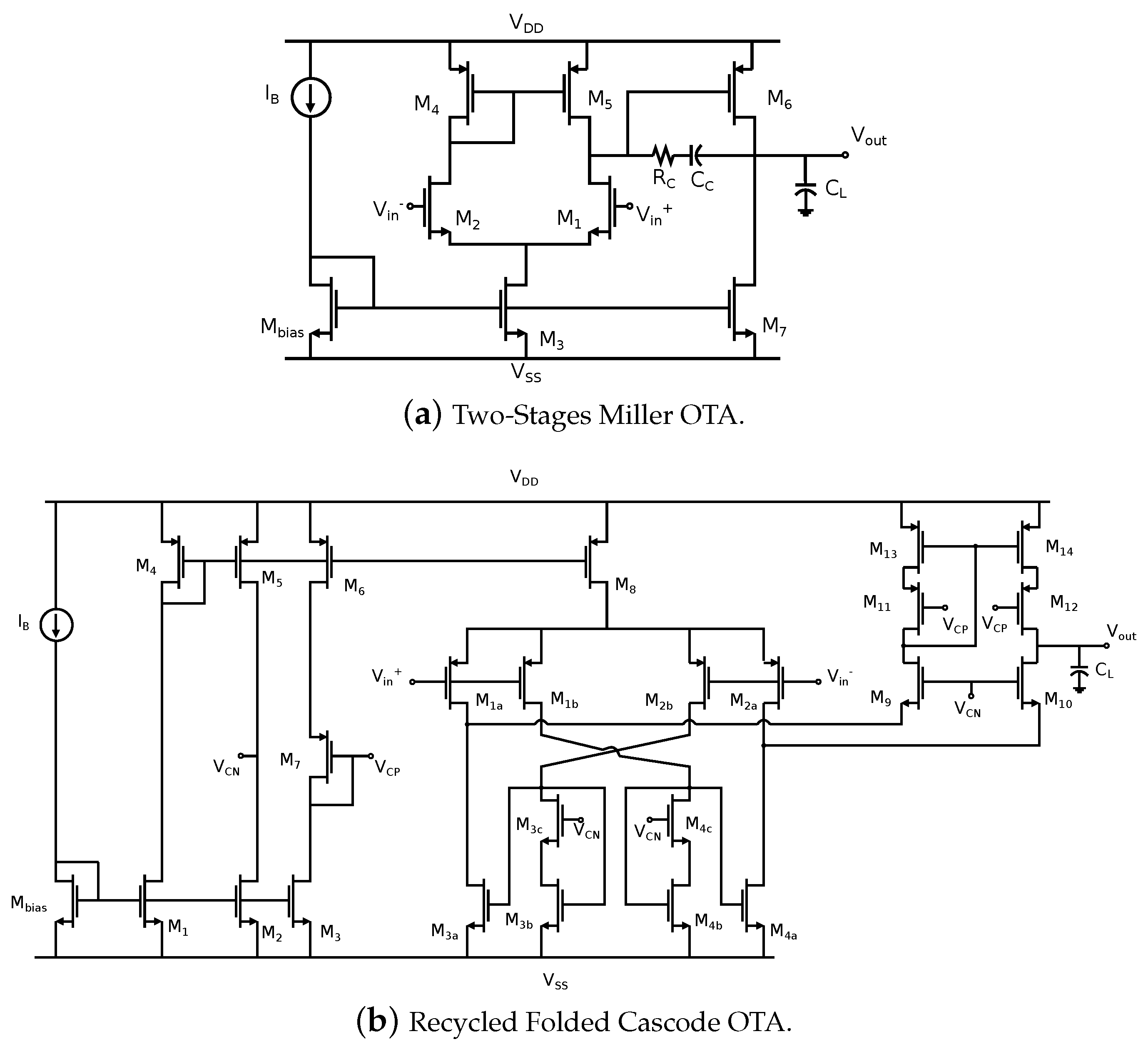
5.1. Sizing the Two-Stage Miller Amplifier
5.2. Recycled Folded Cascode Operational Transconductance Amplifier
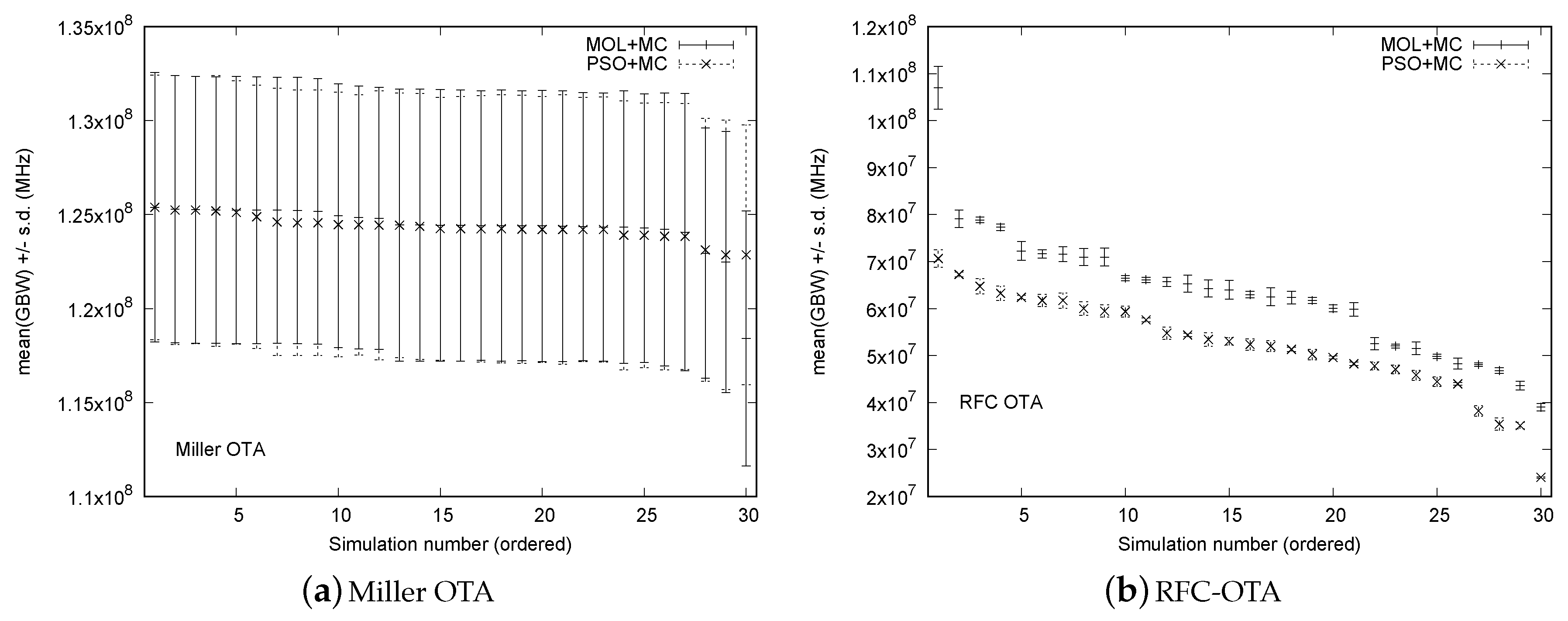
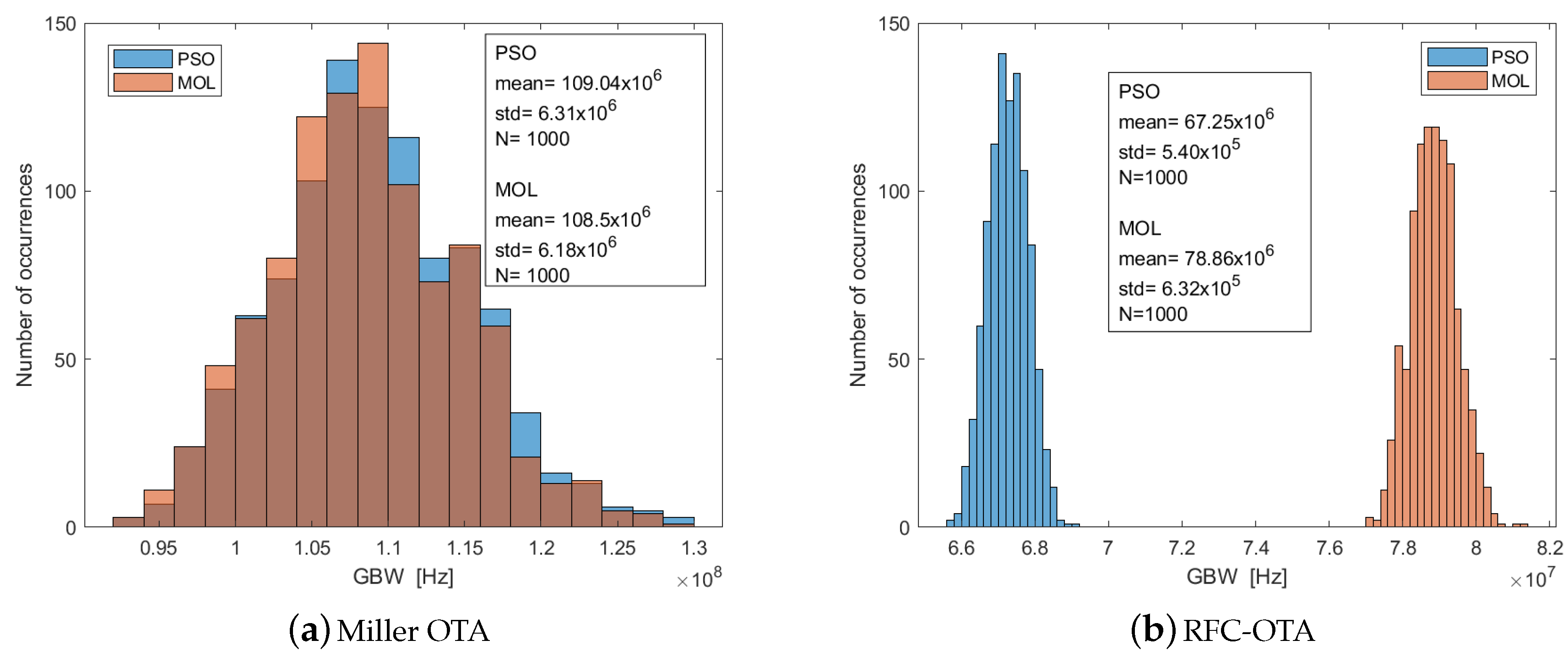
5.3. Monte Carlo and PVT Analyses
5.3.1. Monte Carlo Analysis
5.3.2. PVT Analysis
6. Conclusions
Author Contributions
Funding
Conflicts of Interest
References
- Ramos, F.G.R.; Mussolini, T.P.; Moreno, R.L.; Pimenta, T.C. A CMOS temperature-independent current reference optimized for mixed-signal applications. Integration 2019, 66, 88–95. [Google Scholar] [CrossRef]
- Afacan, E. Inversion coefficient optimization based Analog/RF circuit design automation. Microelectron. J. 2019, 83, 86–93. [Google Scholar] [CrossRef]
- Feizbakhsh, S.V.; Yosefi, G. An enhanced fast slew rate recycling folded cascode Op-Amp with general improvement in 180 nm CMOS process. AEU-Int. J. Electron. Commun. 2019, 101, 200–217. [Google Scholar] [CrossRef]
- Jomehei, M.G.; Sheikhaei, S. A low-power low-noise CMOS bio-potential amplifier for multi-channel neural recording with active DC-rejection and current sharing. Microelectron. J. 2019, 83, 197–211. [Google Scholar] [CrossRef]
- Ghosh, S.; De, B.P.; Kar, R.; Mal, A.K. Symbiotic organisms search algorithm for optimal design of CMOS two-stage op-amp with nulling resistor and robust bias circuit. IET Circuits Devices Syst. 2019, 13, 679–688. [Google Scholar] [CrossRef]
- Hemmati, M.J.; Dehghani, R.; Hakimi, A. A low-voltage swing-enhanced Colpitts CMOS LC-QVCO based on first-harmonics coupling. Microelectron. J. 2019, 85, 6–16. [Google Scholar] [CrossRef]
- Passos, F.; Martins, R.; Lourenço, N.; Roca, E.; Póvoa, R.; Canelas, A.; Castro-López, R.; Horta, N.; Fernández, F.V. Enhanced systematic design of a voltage controlled oscillator using a two-step optimization methodology. Integration 2018, 63, 351–361. [Google Scholar] [CrossRef] [Green Version]
- Kote, V.; Kubacak, A.; Vacula, P.; Jakovenko, J.; Husak, M. Automated pre-placement phase as a part of robust analog-mixed signal physical design flow. Integration 2018, 63, 18–30. [Google Scholar] [CrossRef]
- Maji, K.; De, B.; Kar, R.; Mandal, D.; Ghoshal, S. CMOS analog amplifier circuits design using seeker optimization algorithm. IETE J. Res. 2019, 1–10. [Google Scholar] [CrossRef]
- Shokouhifar, M.; Jalali, A. Simplified symbolic transfer function factorization using combined artificial bee colony and simulated annealing. Appl. Soft Comput. 2017, 55, 436–451. [Google Scholar] [CrossRef]
- De Venuto, D.; Mezzina, G.; Rabaey, J. Automatic 3D Design for Efficiency Optimization of a Class E Power Amplifier. IEEE Trans. Circuits Syst. II Express Briefs 2018, 65, 201–205. [Google Scholar] [CrossRef]
- Boni, A.; Giuffredi, L.; Pietrini, G.; Magnanini, A.; Tonelli, M. Design-oriented model for power-driven design optimization of SC Sigma-Delta modulators. Int. J. Circuit Theory Appl. 2018, 46, 707–728. [Google Scholar] [CrossRef]
- Castejón, F.; Carmona, E.J. Automatic design of analog electronic circuits using grammatical evolution. Appl. Soft Comput. 2018, 62, 1003–1018. [Google Scholar] [CrossRef]
- Moreto, R.; Thomaz, C.; Gimenez, S. Impact of designer knowledge in the interactive evolutionary optimisation of analogue CMOS ICs by using iMTGSPICE. Electron. Lett. 2018, 55, 16–18. [Google Scholar] [CrossRef]
- Martins, R.; Lourenco, N.; Horta, N.; Yin, J.; Mak, P.I.; Martins, R.P. Many-Objective Sizing Optimization of a Class-C/D VCO for Ultralow-Power IoT and Ultralow-Phase-Noise Cellular Applications. IEEE Trans. Large Scale Integr. (VLSI) Syst. 2019, 27, 69–82. [Google Scholar] [CrossRef]
- Passos, F.; Gonzalez-Echevarria, R.; Roca, E.; Castro-López, R.; Fernandez, F. A two-step surrogate modeling strategy for single-objective and multi-objective optimization of radiofrequency circuits. Soft Comput. 2019, 23, 4911–4925. [Google Scholar] [CrossRef] [Green Version]
- De, B.P.; Maji, K.B.; Kar, R.; Mandal, D.; Ghoshal, S.P. Design of Optimal CMOS Analog Amplifier Circuits Using a Hybrid Evolutionary Optimization Technique. J. Circuits Syst. Comput. 2018, 27, 1850029. [Google Scholar] [CrossRef]
- Sanabria-Borbón, A.; Tlelo-Cuautle, E. Sizing analogue integrated circuits by integer encoding and NSGA-II. IETE Tech. Rev. 2018, 35, 237–243. [Google Scholar] [CrossRef]
- Garde, M.P.; Lopez-Martin, A.; Carvajal, R.G.; Ramírez-Angulo, J. Super Class-AB Recycling Folded Cascode OTA. IEEE J. Solid-State Circuits 2018, 53, 2614–2623. [Google Scholar] [CrossRef]
- Aminzadeh, H.; Dashti, M.A. Dual loop cascode-Miller compensation with damping factor control unit for three-stage amplifiers driving ultralarge load capacitors. Int. J. Circuit Theory Appl. 2019, 47, 1–18. [Google Scholar] [CrossRef] [Green Version]
- Yosefi, G. The high recycling folded cascode (HRFC): A general enhancement of the recycling folded cascode operational amplifier. Microelectron. J. 2019, 89, 70–90. [Google Scholar] [CrossRef]
- Khade, A.S.; Vyas, V.; Sutaone, M. Performance enhancement of advanced recycling folded cascode operational transconductance amplifier using an unbalanced biased input stage. Integration 2019, 69, 242–250. [Google Scholar] [CrossRef]
- Lv, X.; Zhao, X.; Wang, Y.; Wen, B. An improved non-linear current recycling folded cascode OTA with cascode self-biasing. AEU-Int. J. Electron. Commun. 2019, 101, 182–191. [Google Scholar] [CrossRef]
- Garde, M.P.; Lopez-Martin, A.; Algueta, J.M.; Carvajal, R.G.; Ramirez-Angulo, J. Class AB amplifier with enhanced slew rate and GBW. Int. J. Circuit Theory Appl. 2019, 47, 1199–1210. [Google Scholar] [CrossRef]
- Cellucci, D.; Centurelli, F.; Di Stefano, V.; Monsurrò, P.; Pennisi, S.; Scotti, G.; Trifiletti, A. 0.6-V CMOS cascode OTA with complementary gate-driven gain-boosting and forward body bias. Int. J. Circuit Theory Appl. 2020, 48, 15–27. [Google Scholar] [CrossRef]
- Centurelli, F.; Monsurrò, P.; Trifiletti, A. High-gain, high-CMRR class AB operational transconductance amplifier based on the flipped voltage follower. Int. J. Circuit Theory Appl. 2019, 47, 499–512. [Google Scholar] [CrossRef]
- Veldandi, H.; Shaik, R.A. Low-voltage PVT-insensitive bulk-driven OTA with enhanced DC gain in 65-nm CMOS process. AEU-Int. J. Electron. Commun. 2018, 90, 88–96. [Google Scholar] [CrossRef]
- Carbajal-Gomez, V.H.; Tlelo-Cuautle, E.; Muñoz-Pacheco, J.M.; de la Fraga, L.G.; Sanchez-Lopez, C.; Fernandez-Fernandez, F.V. Optimization and CMOS design of chaotic oscillators robust to PVT variations. Integration 2019, 65, 32–42. [Google Scholar] [CrossRef]
- Guerra-Gomez, I.; Tlelo-Cuautle, E. Sizing analog integrated circuits by current-branches-bias assignments with heuristics. Elektron. Ir Elektrotechnika 2013, 19, 81–86. [Google Scholar] [CrossRef]
- Mallick, S.; Kar, R.; Ghoshal, S.; Mandal, D. Optimal sizing and design of CMOS analogue amplifier circuits using craziness-based particle swarm optimization. Int. J. Numer. Model. Electron. Netw. Devices Fields 2016, 29, 943–966. [Google Scholar] [CrossRef]
- Razavi, B. Fundamentals of Microelectronics; Wiley: Hoboken, NJ, USA, 2008. [Google Scholar]
- Asaithambi, S.; Rajappa, M. Swarm intelligence-based approach for optimal design of CMOS differential amplifier and comparator circuit using a hybrid salp swarm algorithm. Rev. Sci. Instrum. 2018, 89, 054702. [Google Scholar] [CrossRef] [PubMed]
- Maji, K.B.; Kar, R.; Mandal, D.; Ghoshal, S. Optimal design of low power high gain and high speed CMOS circuits using fish swarm optimization algorithm. Int. J. Mach. Learn. Cybern. 2018, 9, 771–786. [Google Scholar] [CrossRef]
- Singh, C.L.; Anandini, C.; Gogoi, A.J.; Baishnab, K. Automated sizing of low-noise CMOS analog amplifier using ALCPSO optimization algorithm. J. Inf. Optim. Sci. 2018, 39, 99–111. [Google Scholar] [CrossRef]
- Wang, D.; Tan, D.; Liu, L. Particle swarm optimization algorithm: An overview. Soft Comput. 2018, 22, 387–408. [Google Scholar] [CrossRef]
- Saha, N.; Panda, A.; Panda, S. Speed control with torque ripple reduction of switched reluctance motor by many optimizing liaison technique. J. Electr. Syst. Inf. Technol. 2018, 5, 829–842. [Google Scholar] [CrossRef]
- Kaveh, A. Advances in Metaheuristic Algorithms for Optimal Design of Structures; Springer: Berlin/Heidelberg, Germany, 2014. [Google Scholar]
- Particle Swarm Optimization in MATLAB. Available online: http://yarpiz.com/50/ypea102-particle-swarm-optimization (accessed on 22 May 2019).
- Cabrera, J.C.F.; Coello, C.A.C. Handling constraints in particle swarm optimization using a small population size. In Proceedings of the Mexican International Conference on Artificial Intelligence, Aguascalientes, Mexico, 4–10 November 2007; pp. 41–51. [Google Scholar]
- Mojarad, M.; Kamarei, M. Low-voltage high-gain large-capacitive-load amplifiers in 90-nm CMOS technology. AEU-Int. J. Electron. Commun. 2015, 69, 666–672. [Google Scholar] [CrossRef]
- Riad, J.; Estrada-López, J.J.; Sánchez-Sinencio, E. Classification and Design Space Exploration of Low-Power Three-Stage Operational Transconductance Amplifier Architectures for Wide Load Ranges. Electronics 2019, 8, 1268. [Google Scholar] [CrossRef] [Green Version]
- Zhang, Q.; Zhao, X.; Zhang, X.; Zhang, Q. Multipath recycling method for transconductance enhancement of folded cascade amplifier. AEU-Int. J. Electron. Commun. 2017, 72, 1–7. [Google Scholar] [CrossRef]
- Ragheb, A.; Kim, H. Ultra-low power OTA based on bias recycling and subthreshold operation with phase margin enhancement. Microelectron. J. 2017, 60, 94–101. [Google Scholar] [CrossRef]
- Wang, Y.; Zhang, Q.; Yu, S.S.; Zhao, X.; Trinh, H.; Shi, P. A Robust Local Positive Feedback Based Performance Enhancement Strategy for Non-Recycling Folded Cascode OTA. IEEE Trans. Circuits Syst. I Regul. Pap. 2020, 1–12. [Google Scholar] [CrossRef]
- Yan, Z.; Mak, P.I.; Martins, R. Double recycling technique for folded-cascode OTA. Analog Integr. Circuits Signal Process. 2012, 71, 137–141. [Google Scholar] [CrossRef]
- Sanabria-Borbón, A.C.; Soto-Aguilar, S.; Estrada-López, J.J.; Allaire, D.; Sánchez-Sinencio, E. Gaussian-Process-Based Surrogate for Optimization-Aided and Process-Variations-Aware Analog Circuit Design. Electronics 2020, 9, 685. [Google Scholar] [CrossRef] [Green Version]
- Zhao, X.; Zhang, Q.; Wang, Y.; Deng, M. Transconductance and slew rate improvement technique for current recycling folded cascode amplifier. AEU-Int. J. Electron. Commun. 2016, 70, 326–330. [Google Scholar] [CrossRef]


| Topology | Miller OTA | Recycled-Folded-Cascode OTA |
|---|---|---|
| UMC CMOS technology | 0.18 m | 0.18 m |
| Voltage supply (V) | ±0.9 | ±0.9 |
| (pF) | 5 | 5 |
| DC Gain (dB) | ≥60 | ≥60 |
| GBW (MHz) | >100 | >20 |
| PM () | >45 | >45 |
| CMRR (dB) | ≥60 | ≥60 |
| SR+ (V/s) | ≥10 | ≥10 |
| SR− (V/s) | ≥10 | ≥10 |
| PSRR+ (dB) | ≥60 | ≥60 |
| PSRR− (dB) | ≥60 | ≥60 |
| Power Dissipation (mW) | <5 | <10 |
| MOS AREA (m) | ≤1500 | ≤4500 |
| SAT | ≥3 | ≥3 |
| Solution | 1 | 2 | 3 | 4 | 5 | 6 | 7 | 8 | 9 | 10 |
|---|---|---|---|---|---|---|---|---|---|---|
| GBW (MHz) | 108.93 | 108.88 | 108.26 | 108.32 | 107.85 | 107.85 | 108.41 | 108.37 | 108.19 | 108.16 |
| DC GAIN (dB) | 60.597 | 60.884 | 60.827 | 62.273 | 60.463 | 60.463 | 62.214 | 62.373 | 62.579 | 62.589 |
| PM () | 52.46 | 51.8 | 53.34 | 51.72 | 54.06 | 54.06 | 51.45 | 51.78 | 51.53 | 51.6 |
| CMRR (dB) | 70.865 | 72.584 | 74.884 | 72.005 | 66.5559 | 66.5559 | 73.557 | 72.005 | 71.1141 | 67.7927 |
| SR+ (v/s) | 45 | 45 | 45 | 45 | 45 | 44 | 45 | 45 | 45 | 45 |
| SR− (v/s) | 26 | 26 | 26 | 26 | 26 | 24 | 26 | 26 | 26 | 26 |
| PSRR+ (dB) | 67.549 | 67.715 | 67.391 | 67.777 | 67.15 | 67.15 | 67.822 | 67.777 | 67.845 | 67.831 |
| PSRR− (dB) | 72.903 | 73.566 | 73.428 | 75.072 | 72.605 | 72.605 | 74.939 | 75.072 | 75.793 | 75.818 |
| Power dissipation (mW) | 3.68 | 3.73 | 3.72 | 3.75 | 3.81 | 3.81 | 3.73 | 3.74 | 3.83 | 3.73 |
| MOS AREA (m) | 1306.77 | 1255.58 | 1049.35 | 1179.94 | 1075.95 | 1075.95 | 1255.85 | 1183.72 | 1085.83 | 1073.07 |
| 5446.5 | 5444 | 5413 | 5416 | 5392.5 | 5392.5 | 5420.5 | 5416 | 5409.5 | 5408 | |
| 1300 | 1300 | 1300 | 1300 | 1300 | 1200 | 1300 | 1300 | 1300 | 1300 | |
| W1 (M1,M2) (m) | 49.5 | 49.32 | 49.14 | 49.77 | 49.23 | 49.23 | 49.86 | 50.77 | 49.68 | 49.68 |
| W2 (M4,M5,M6) (m) | 63.72 | 55.35 | 43.02 | 49.77 | 49.23 | 49.23 | 55.71 | 49.77 | 40.14 | 39.33 |
| W3 (Mb,M3,M7) (m) | 67.5 | 72.45 | 60.57 | 66.69 | 55.26 | 55.26 | 68.67 | 66.69 | 67.68 | 67.05 |
| L1 (M1,M2) (m) | 0.45 | 0.45 | 0.45 | 0.45 | 0.45 | 0.45 | 0.45 | 0.45 | 0.45 | 0.45 |
| L2 (M4,M5,M6) (m) | 0.36 | 0.36 | 0.36 | 0.45 | 0.36 | 0.36 | 0.45 | 0.45 | 0.45 | 0.45 |
| L3 (Mb,M3,M7) (m) | 0.27 | 0.27 | 0.27 | 0.27 | 0.27 | 0.27 | 0.27 | 0.27 | 0.27 | 0.27 |
| Ib (A) | 88 | 100 | 100 | 100 | 100 | 100 | 100 | 100 | 100 | 100 |
| Solution | 1 | 2 | 3 | 4 | 5 | 6 | 7 | 8 | 9 | 10 |
|---|---|---|---|---|---|---|---|---|---|---|
| GBW (MHz) | 107.82 | 108.57 | 108.92 | 108.95 | 108.98 | 109 | 108.98 | 108.98 | 109 | 109 |
| DC GAIN (dB) | 61.3 | 61.192 | 60.77 | 60.778 | 60.719 | 60.617 | 60.659 | 60.66 | 60.592 | 60.57 |
| PM () | 52.69 | 52.01 | 51.26 | 51.79 | 51.85 | 51.8 | 51.87 | 51.9 | 51.89 | 52.02 |
| CMRR (dB) | 70.02 | 67.716 | 67.07 | 73.052 | 70.5329 | 68.235 | 68.759 | 74.41 | 67.652 | 74.42 |
| SR+ (v/s) | 45 | 45 | 45 | 45 | 45 | 45 | 45 | 45 | 45 | 45 |
| SR− (v/s) | −26 | −26 | −26 | −27 | −27 | −27 | −26 | −26 | −26 | −26 |
| PSRR+ (dB) | 67.759 | 67.716 | 67.785 | 67.7 | 67.68 | 67.671 | 67.668 | 67.662 | 67.652 | 67.626 |
| PSRR− (dB) | 74.337 | 74.293 | 73.314 | 73.324 | 73.187 | 72.96 | 73.053 | 73.064 | 72.902 | 72.864 |
| Power dissipation (mW) | 3.8 | 3.8 | 3.85 | 3.84 | 3.84 | 3.85 | 3.85 | 3.85 | 3.85 | 3.85 |
| MOS AREA (m) | 697.03 | 686.11 | 966.24 | 893.59 | 922.47 | 997.59 | 958.66 | 950.21 | 1003.26 | 994.03 |
| 5429.5 | 5428.5 | 5446 | 5447.5 | 5449 | 5450 | 5449 | 5449 | 5450 | 5450 | |
| 1300 | 1300 | 1300 | 1350 | 1350 | 1350 | 1300 | 1300 | 1300 | 1300 | |
| W1 (M1,M2) (m) | 49.14 | 49.14 | 49.5 | 49.41 | 49.5 | 49.59 | 49.5 | 49.5 | 49.59 | 49.59 |
| W2 (M4,M5,M6) (m) | 41.76 | 40.86 | 67.86 | 61.11 | 63.99 | 71.37 | 67.59 | 66.78 | 72 | 71.19 |
| W3 (Mb,M3,M7) (m) | 72 | 70.29 | 76.41 | 72.45 | 72 | 72.36 | 71.91 | 71.64 | 71.73 | 70.74 |
| L1 (M1,M2) (m) | 0.45 | 0.45 | 0.45 | 0.45 | 0.45 | 0.45 | 0.45 | 0.45 | 0.45 | 0.45 |
| L2 (M4,M5,M6) (m) | 0.36 | 0.36 | 0.36 | 0.36 | 0.36 | 0.36 | 0.36 | 0.36 | 0.36 | 0.36 |
| L3 (Mb,M3,M7) (m) | 0.27 | 0.27 | 0.27 | 0.27 | 0.27 | 0.27 | 0.27 | 0.27 | 0.27 | 0.27 |
| Ib (A) | 88 | 100 | 100 | 100 | 100 | 100 | 100 | 100 | 100 | 100 |
| Solution | 1 | 2 | 3 | 4 | 5 | 6 | 7 | 8 | 9 | 10 |
|---|---|---|---|---|---|---|---|---|---|---|
| GBW (MHz) | 67 | 53 | 54 | 47 | 51 | 49 | 48 | 43 | 47 | 44 |
| DC GAIN (dB) | 68 | 67 | 70 | 68 | 67 | 64 | 71 | 72 | 69 | 64 |
| PM () | 66.51 | 62.92 | 62.45 | 65.88 | 56.88 | 61.93 | 50.06 | 59.83 | 65.42 | 69.8 |
| CMRR (dB) | 106.2 | 103 | 107.606 | 99.932 | 106.952 | 99.225 | 109.857 | 105.176 | 107.558 | 99.235 |
| SR+ (v/s) | 17 | 18 | 17 | 14 | 16 | 17 | 16 | 11 | 11 | 10 |
| SR− (v/s) | −28 | −42 | −48 | −52 | −40 | −41 | −35 | −37 | −35 | −33 |
| PSRR+ (dB) | 67 | 67 | 70 | 68 | 67 | 65 | 71 | 72 | 70 | 64 |
| PSRR− (dB) | 99 | 90 | 106 | 99 | 91 | 85 | 111 | 119 | 90 | 88 |
| Power dissipation | 7 | 6 | 6 | 2 | 6 | 5 | 6 | 5 | 6 | 6 |
| MOS AREA (m) | 3293.53 | 3501.53 | 3482.8 | 3605.79 | 4076.81 | 3345.75 | 4217.65 | 4081.78 | 4012.82 | 3536.89 |
| 3361.9 | 3050 | 2718 | 3651.23 | 2566.4 | 2477.3 | 2411.85 | 3013.25 | 2449.32 | 2463.54 | |
| 850 | 900 | 850 | 1076 | 800 | 850 | 800 | 753 | 572 | 555 | |
| W1 (m) | 90 | 90 | 90 | 11.79 | 70.56 | 37.26 | 47.34 | 49.77 | 90 | 90 |
| W2 (m) | 75.69 | 71.64 | 90 | 90 | 90 | 90 | 90 | 88.56 | 71.46 | 55.17 |
| W3 (m) | 71.1 | 90 | 48.6 | 90 | 90 | 90 | 90 | 90 | 90 | 90 |
| W4 (m) | 13.05 | 0.99 | 7.65 | 55.26 | 26.91 | 0.99 | 49.32 | 22.23 | 0.99 | 0.99 |
| W5 (m) | 0.99 | 28.62 | 39.51 | 0.99 | 90 | 33.96 | 19.17 | 0.99 | 6.57 | 29.61 |
| W6 (m) | 41.4 | 27.09 | 36.99 | 13.95 | 14.4 | 11.45 | 90 | 27.72 | 90 | 87.66 |
| W7 (m) | 27.81 | 36.36 | 33.48 | 90 | 90 | 27.15 | 41.49 | 90 | 72.09 | 90 |
| W8 (m) | 90 | 89.73 | 90 | 57.06 | 33.84 | 90 | 89.37 | 90 | 64.35 | 10.08 |
| L1 (m) | 0.54 | 0.63 | 0.9 | 0.18 | 0.9 | 0.9 | 0.72 | 0.9 | 0.9 | 0.63 |
| L2 (m) | 0.27 | 0.27 | 0.36 | 0.72 | 0.36 | 0.36 | 0.36 | 0.36 | 0.18 | 0.18 |
| L3 (m) | 0.45 | 0.45 | 0.36 | 0.36 | 0.54 | 0.54 | 0.72 | 0.9 | 0.9 | 0.9 |
| L4 (m) | 0.45 | 0.18 | 0.81 | 0.72 | 0.63 | 0.18 | 0.72 | 0.54 | 0.27 | 0.18 |
| L5 (m) | 0.72 | 0.27 | 0.18 | 0.27 | 0.36 | 0.27 | 0.9 | 0.9 | 0.9 | 0.18 |
| L6 (m) | 0.81 | 0.63 | 0.54 | 0.18 | 0.27 | 0.45 | 0.72 | 0.9 | 0.9 | 0.72 |
| L7 (m) | 0.18 | 0.36 | 0.18 | 0.54 | 0.63 | 0.18 | 0.27 | 0.9 | 0.54 | 0.45 |
| L8 (m) | 0.36 | 0.63 | 0.45 | 0.18 | 0.27 | 0.9 | 0.54 | 0.54 | 0.45 | 0.18 |
| Ib (A) | 100 | 91 | 100 | 65 | 100 | 100 | 100 | 73 | 96 | 90 |
| Solution | 1 | 2 | 3 | 4 | 5 | 6 | 7 | 8 | 9 | 10 |
|---|---|---|---|---|---|---|---|---|---|---|
| GBW (MHz) | 78 | 95 | 71 | 66 | 66 | 65 | 62 | 61 | 60 | 62 |
| DC GAIN (dB) | 64 | 62 | 65 | 69 | 69 | 62 | 62 | 68 | 63 | 70 |
| PM () | 65.07 | 67.08 | 68.08 | 63.59 | 64.22 | 82.7 | 64.36 | 64.38 | 56.55 | 54.71 |
| CMRR (dB) | 100 | 98 | 101 | 104 | 105 | 97 | 111 | 100 | 104 | 87 |
| SR+ (v/s) | 21 | 24 | 20 | 20 | 20 | 12 | 18 | 24 | 19 | 15 |
| SR− (v/s) | 75 | 24 | 50 | 51 | 51 | 59 | 17 | 46 | 43 | 17 |
| PSRR+ (dB) | 63 | 62 | 65 | 70 | 70 | 63 | 61 | 68 | 63 | 68 |
| PSRR− (dB) | 87 | 84 | 94 | 93 | 93 | 84 | 90 | 104 | 85 | 94 |
| Power dissipation | 7 | 7 | 6 | 6 | 6 | 6 | 6 | 6 | 6 | 8 |
| MOS AREA (m) | 3701.18 | 4284.09 | 4007.16 | 4284.09 | 4251.3 | 2726.97 | 2642.06 | 3779.43 | 4036.81 | 3808.75 |
| 3900 | 4750 | 3550 | 3300 | 3300 | 3250 | 3100 | 3050 | 3000 | 3100 | |
| 1050 | 1200 | 1000 | 1000 | 1000 | 600 | 900 | 1200 | 950 | 750 | |
| W1 (m) | 90 | 90 | 90 | 90 | 90 | 90 | 90 | 90 | 90 | 25.83 |
| W2 (m) | 90 | 76.59 | 90 | 90 | 90 | 90 | 51.66 | 90 | 90 | 90 |
| W3 (m) | 90 | 90 | 90 | 90 | 90 | 21.15 | 72.9 | 19.8 | 90 | 90 |
| W4 (m) | 22.86 | 8.19 | 7.2 | 0.99 | 0.99 | 0.99 | 17.82 | 18.72 | 18.27 | 25.29 |
| W5 (m) | 0.99 | 0.99 | 0.99 | 0.99 | 0.99 | 1.8 | 0.99 | 0.99 | 90 | 0.99 |
| W6 (m) | 59.94 | 83.97 | 90 | 90 | 90 | 29.52 | 14.22 | 90 | 90 | 54.99 |
| W7 (m) | 14.13 | 21.96 | 90 | 90 | 90 | 90 | 15.58 | 90 | 16.2 | 90 |
| W8 (m) | 90 | 57.33 | 22.23 | 90 | 90 | 19.08 | 21.51 | 90 | 38.61 | 90 |
| L1 (m) | 0.63 | 0.45 | 0.9 | 0.9 | 0.9 | 0.54 | 0.9 | 0.9 | 0.9 | 0.18 |
| L2 (m) | 0.27 | 0.27 | 0.36 | 0.36 | 0.36 | 0.27 | 0.27 | 0.36 | 0.36 | 0.18 |
| L3 (m) | 0.36 | 0.36 | 0.36 | 0.36 | 0.36 | 0.18 | 0.36 | 0.18 | 0.36 | 0.9 |
| L4 (m) | 0.36 | 0.18 | 0.18 | 0.18 | 0.18 | 0.18 | 0.9 | 0.36 | 0.45 | 0.9 |
| L5 (m) | 0.9 | 0.18 | 0.18 | 0.18 | 0.18 | 0.54 | 0.9 | 0.18 | 0.18 | 0.9 |
| L6 (m) | 0.54 | 0.63 | 0.9 | 0.9 | 0.9 | 0.36 | 0.18 | 0.9 | 0.9 | 0.9 |
| L7 (m) | 0.18 | 0.18 | 0.63 | 0.54 | 0.36 | 0.45 | 0.18 | 0.45 | 0.18 | 0.63 |
| L8 (m) | 0.27 | 0.27 | 0.18 | 0.27 | 0.27 | 0.18 | 0.18 | 0.54 | 0.18 | 0.27 |
| Ib (A) | 100 | 100 | 100 | 100 | 100 | 100 | 100 | 100 | 100 | 100 |
© 2020 by the authors. Licensee MDPI, Basel, Switzerland. This article is an open access article distributed under the terms and conditions of the Creative Commons Attribution (CC BY) license (http://creativecommons.org/licenses/by/4.0/).
Share and Cite
Tlelo-Cuautle, E.; Valencia-Ponce, M.A.; de la Fraga, L.G. Sizing CMOS Amplifiers by PSO and MOL to Improve DC Operating Point Conditions. Electronics 2020, 9, 1027. https://doi.org/10.3390/electronics9061027
Tlelo-Cuautle E, Valencia-Ponce MA, de la Fraga LG. Sizing CMOS Amplifiers by PSO and MOL to Improve DC Operating Point Conditions. Electronics. 2020; 9(6):1027. https://doi.org/10.3390/electronics9061027
Chicago/Turabian StyleTlelo-Cuautle, Esteban, Martín Alejandro Valencia-Ponce, and Luis Gerardo de la Fraga. 2020. "Sizing CMOS Amplifiers by PSO and MOL to Improve DC Operating Point Conditions" Electronics 9, no. 6: 1027. https://doi.org/10.3390/electronics9061027
APA StyleTlelo-Cuautle, E., Valencia-Ponce, M. A., & de la Fraga, L. G. (2020). Sizing CMOS Amplifiers by PSO and MOL to Improve DC Operating Point Conditions. Electronics, 9(6), 1027. https://doi.org/10.3390/electronics9061027