Input Shaping Based on an Experimental Transfer Function for an Electrostatic Microscanner in a Quasistatic Mode

Abstract
:1. Introduction
2. Quasistatic Microscanner
2.1. Characteristics of the Microscanner
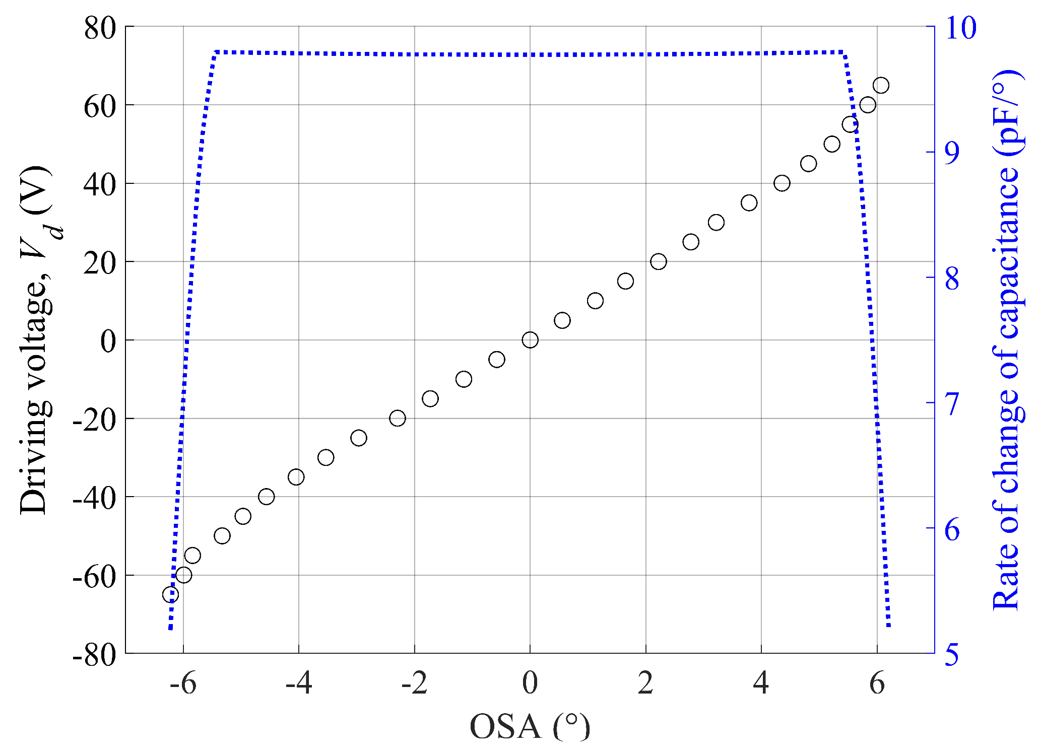
2.2. Linearized Actuation
2.3. Residual Oscillation
3. ISETF Procedure
3.1. Experimental Conditions
3.2. Experimental Setup
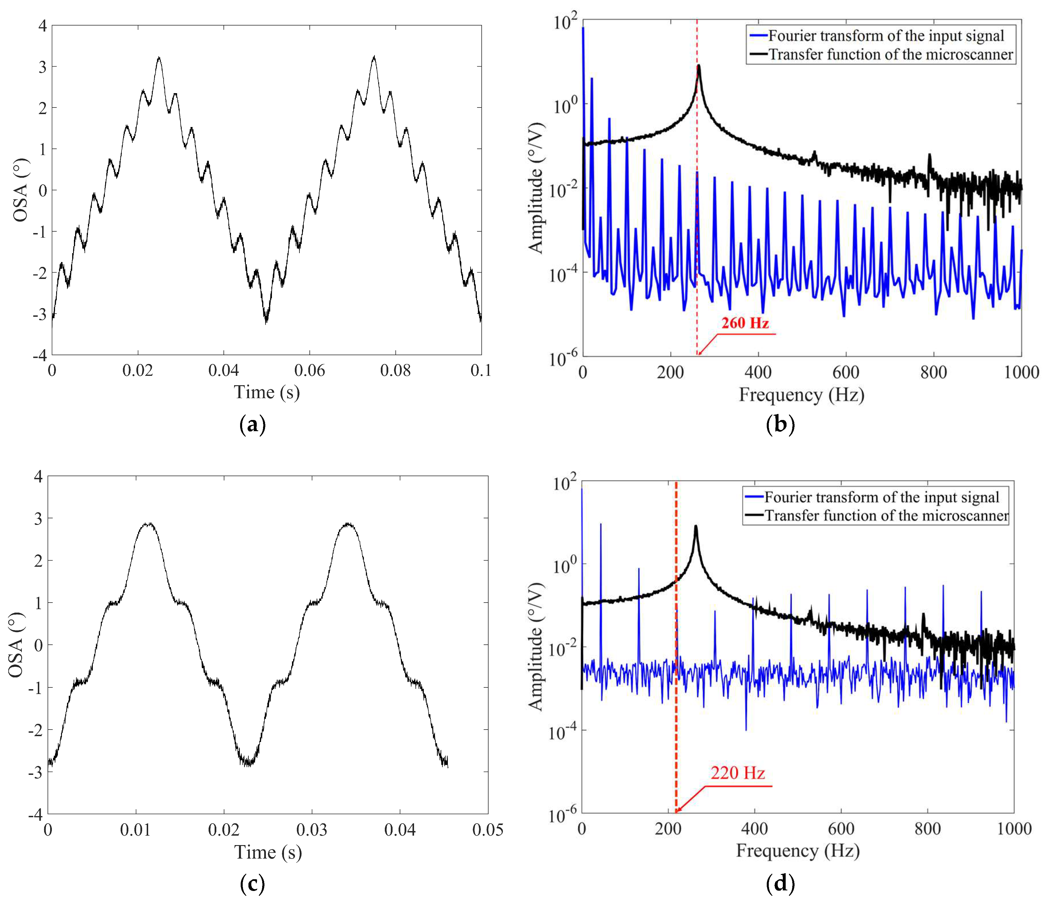
3.3. Extraction of the Experimental Transfer Function
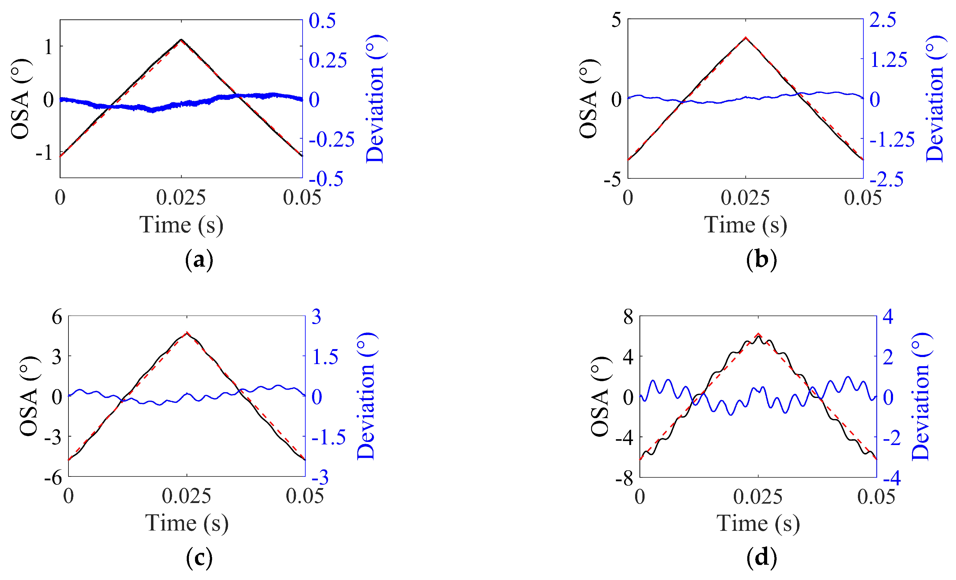
3.4. Input Shaping for Triangular Output
- (1)
- The ideal triangular output, d(t), is Fourier-transformed to obtain D(f) in the frequency domain by using Matlab software.
- (2)
- D(f) is divided by H(f) to acquire the input signal in the frequency domain, V(f), as shown in Equation (5).
- (3)
- The shaped input signal in the time domain, v(t), is obtained through inverse fast Fourier transform (inverse FFT).
- (4)
- The calculated shaped input signal in the time domain, v(t), is converted to the filename extension ‘.tfw’ using ArbExpress Application software so that it can be recognized in the function generator.
- (5)
- The converted shaped input signal is stored in the function generator through a universal serial bus (USB) memory so that it can be applied to the microscanner.
4. Application Limits of ISETF
4.1. Optical Scan Angle (OSA)
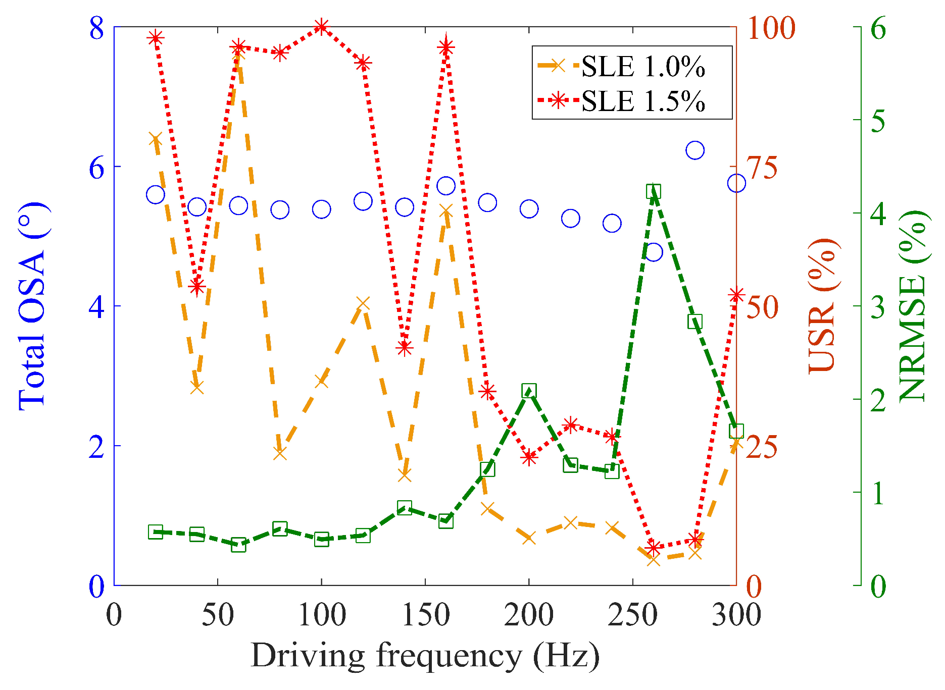
4.2. Driving Frequency
4.3. Comparison to Other Methods
5. Conclusions
Author Contributions
Funding
Conflicts of Interest
Abbreviations
| ETF | Experimental transfer function |
| ISETF | Input shaping method based on an experimental transfer function |
| NRMSE | Normalized root-mean-square error |
| OSA | Optical scan angle |
| SLE | Scan line error |
| USR | Usable scan range |
References
- Jung, W.; McCormick, D.T.; Zhang, J.; Wang, L.; Tien, N.C.; Chen, Z. Three-dimensional endoscopic optical coherence tomography by use of a two-axis microelectromechanical scanning mirror. Appl. Phys. Letters 2006, 88. [Google Scholar] [CrossRef]
- Hofmann, U.; Janes, J.; Quenzer, H.-J. High-Q MEMS resonators for laser beam scanning displays. Micromachines 2012, 3, 509–528. [Google Scholar] [CrossRef]
- Milanović, V.; Kasturi, A.; Yang, J.; Hu, F. Closed-loop control of gimbal-less MEMS mirrors for increased bandwidth in LiDAR applications. In Proceedings of the Laser Radar Technology and Applications XXII 2017, Anaheim, CA, USA, 9–13 April 2017; p. 101910N. [Google Scholar]
- Iyer, V.; Losavio, B.E.; Saggau, P. Compensation of spatial and temporal dispersion for acousto-optic multiphoton laser-scanning microscopy. J. Biomed. Opt. 2003, 8, 460–471. [Google Scholar] [CrossRef]
- Lu, C.D.; Kraus, M.F.; Potsaid, B.; Liu, J.J.; Choi, W.; Jayaraman, V.; Cable, A.E.; Hornegger, J.; Duker, J.S.; Fujimoto, J.G. Handheld ultrahigh speed swept source optical coherence tomography instrument using a MEMS scanning mirror. Biomed. Opt. Expr. 2013, 5, 293–311. [Google Scholar] [CrossRef] [PubMed] [Green Version]
- Schroedter, R.; Janschek, K.; Sandner, T. Jerk and current limited flatness-based open loop control of foveation scanning electrostatic micromirrors. Proc. IFAC Vol. 2014, 47, 2685–2690. [Google Scholar] [CrossRef]
- Cogliati, A.; Canavesi, C.; Hayes, A.; Tankam, P.; Duma, V.F.; Santhanam, A.; Thompson, K.P.; Rolland, J.P. MEMS-based handheld scanning probe with pre-shaped input signals for distortion-free images in Gabor-domain optical coherence microscopy. Opt. Expr. 2016, 24, 13365–13374. [Google Scholar] [CrossRef]
- Mohammadi, A.; Fowler, A.G.; Yong, Y.K.; Moheimani, S.O.R. A feedback controlled MEMS nanopositioner for on-chip high-speed AFM. J. Microelectromech. Syst. 2014, 23, 610–619. [Google Scholar] [CrossRef]
- Schroedter, R.; Roth, M.; Janschek, K.; Sandner, T. Flatness-based open-loop and closed-loop control for electrostatic quasi-static microscanners using jerk-limited trajectory design. Mechatronics 2018, 56, 318–331. [Google Scholar] [CrossRef]
- Borovic, B.; Liu, A.Q.; Popa, D.; Cai, H.; Lewis, F.L. Open-loop versus closed-loop control of MEMS devices: choices and issues. J. Microelectromech. Microeng. 2005, 15, 1917–1924. [Google Scholar] [CrossRef]
- Pal, S.; Xie, H. Pre-shaped open loop drive of electrothermal micromirror by continuous and pulse width modulated waveforms. IEEE J. Quantum Electron. 2010, 46, 1254–1260. [Google Scholar] [CrossRef]
- Krylov, S.; Maimon, R. Pull-in dynamics of an elastic beam actuated by continuously distributed electrostatic force. J. Vib. Acoust. 2004, 126, 332–342. [Google Scholar] [CrossRef]
- Yu, S.; Piyabongkarn, D.; Sezen, A.; Nelson, B.J.; Rajamani, R.; Schoch, R.; Potasek, D.P. A novel dual-axis electrostatic microactuation system for micromanipulation. In Proceedings of the IEEE/RSJ International Conference on Intelligent Robots and System, Lausanne, Switzerland, 30 September–4 October 2002; pp. 1796–1801. [Google Scholar]
- Horsley, D.A.; Wongkomet, N.; Horowitz, R.; Pisano, A.P. Precision positioning using a microfabricated electrostatic actuator. IEEE T Magn. 1999, 35, 993–999. [Google Scholar] [CrossRef]
- Bazaei, A.; Maroufi, M.; Mohammadi, A.; Moheimani, S.O.R. Displacement sensing with silicon flexures in MEMS nanopositioners. J. Microelectromech. Syst. 2014, 23, 502–504. [Google Scholar] [CrossRef]
- Moon, S.; Lee, J.; Yun, J.; Lim, J.; Gwak, M.-J.; Kim, K.-S.; Lee, J.-H. Two-axis electrostatic gimbaled mirror scanner with self-aligned tilted stationary combs. IEEE Photon. Technol. Letters 2016, 28, 557–560. [Google Scholar] [CrossRef]
- Milanović, V. Linearized gimbal-less two-axis MEMS mirrors. In Proceedings of the Optical Fiber Communication Conference and National Fiber Optic Engineers Conference, San Diego, CA, USA, 22–26 March 2009; p. JThA19. [Google Scholar]


| Parameters | Values |
|---|---|
| Number of fingers per pair of electrodes, N | 126 |
| Thickness of the electrode, t | 50 μm |
| Length of the electrode, le | 175 μm |
| Width of the electrode, we | 5 μm |
| Distance to the rotation axis, lr | 475 μm |
| Electrode gap, g | 5 μm |
| Control method | Open-loop control [9] | This paper | |
| Frequency of fundamental torsional mode (FTM) | 120 Hz | 264 Hz | |
| Total optical scan angle (total OSA) | 20° | 5.6° | |
| 20–40 Hz | Peak-to-peak error | 66.0 m° | 31.9 m° |
| Normalized peak-to-peak error | 0.33 % | 0.57% | |
| 60–220 Hz | Peak-to-peak error | 500.0 m° | 50.4 m° |
| Normalized peak-to-peak error | 2.50% | 0.90% | |
| Control method | Closed-loop control [9] | This paper | |
| 20–140 Hz | Peak-to-peak error | 46.0 m° | 31.4 m° |
| Normalized peak-to-peak error | 0.23 % | 0.56% | |
| 160–220 Hz | Peak-to-peak error | 790.0 m° | 73.9 m° |
| Normalized peak-to-peak error | 3.95 % | 1.32 % | |
© 2019 by the authors. Licensee MDPI, Basel, Switzerland. This article is an open access article distributed under the terms and conditions of the Creative Commons Attribution (CC BY) license (http://creativecommons.org/licenses/by/4.0/).
Share and Cite
Kim, K.; Moon, S.; Kim, J.; Park, Y.; Lee, J.-H. Input Shaping Based on an Experimental Transfer Function for an Electrostatic Microscanner in a Quasistatic Mode. Micromachines 2019, 10, 217. https://doi.org/10.3390/mi10040217
Kim K, Moon S, Kim J, Park Y, Lee J-H. Input Shaping Based on an Experimental Transfer Function for an Electrostatic Microscanner in a Quasistatic Mode. Micromachines. 2019; 10(4):217. https://doi.org/10.3390/mi10040217
Chicago/Turabian StyleKim, Kwanghyun, Seunghwan Moon, Jinhwan Kim, Yangkyu Park, and Jong-Hyun Lee. 2019. "Input Shaping Based on an Experimental Transfer Function for an Electrostatic Microscanner in a Quasistatic Mode" Micromachines 10, no. 4: 217. https://doi.org/10.3390/mi10040217
APA StyleKim, K., Moon, S., Kim, J., Park, Y., & Lee, J.-H. (2019). Input Shaping Based on an Experimental Transfer Function for an Electrostatic Microscanner in a Quasistatic Mode. Micromachines, 10(4), 217. https://doi.org/10.3390/mi10040217