Article

Stable Stacking Faults Bounded by Frank Partial Dislocations in Al7075 Formed through Precipitate and Dislocation Interactions

1
Key Laboratory of Aerospace Materials and Performance (Ministry of Education), School of Materials Science and Engineering, Beijing University of Aeronautics and Astronautics, Beijing 100191, China
2
The Collaborative Innovation Center for Advanced Aero-Engine (CICAAE), Beijing University of Aeronautics and Astronautics, Beijing 100191, China
3
Beijing Key Laboratory of Advanced Nuclear Materials and Physics, Beijing University of Aeronautics and Astronautics, Beijing 100191, China
*
Author to whom correspondence should be addressed.
Crystals 2017, 7(12), 375; https://doi.org/10.3390/cryst7120375
Submission received: 9 November 2017 / Revised: 10 December 2017 / Accepted: 11 December 2017 / Published: 13 December 2017
(This article belongs to the Special Issue Crystal Dislocations: Their Impact on Physical Properties of Crystals)

Abstract

:
Through high-resolution electron microscopy, stacking faults (SFs) due to Frank partial dislocations were found in an aluminum alloy following deformation with low strain and strain rate, while also remaining stable during artificial aging. Extrinsic stacking faults were found surrounded by dislocation areas and precipitates. An intrinsic stacking fault was found between two Guinier-Preston II (GP II) zones when the distance of the two GP II zones was 2 nm. Defects (precipitates and dislocations) are considered to have an influence on the formation of the SFs, as their appearance may cause local strain and promote the gathering of vacancies to lower the energy.

Graphical Abstract

1. Introduction

As is well known, with high stacking-fault energy (SFE) and twin-boundary energy, aluminum and its alloys rarely produce stacking faults (SFs) or microtwins. Producing SFs in high-SFE metals, which could potentially improve the ductility of the metals, has raised considerable interest among scholars [1,2,3,4,5,6,7]. For example, SFs and twins were found in nanocrystal aluminum powders produced by ball milling [5]. Twins were produced in Al-Mg alloy [3] at a high strain rate (102–106 s−1). Most of these findings were made under very extreme conditions, such as high strain and high strain rate.
The SFs and microtwins mentioned above are commonly explained by the generation of Shockley partial dislocation [8,9] (a perfect dislocation divided into two Shockley partial dislocations), while SFs caused by Frank partial dislocations are seldom investigated. Although some SFs led by Frank loop have been found [10,11,12], unfortunately, these SFs were unstable during heating or irradiation.
Alternatively, another effective and widely researched way of improving the performance of aluminum alloys is to produce precipitates [13,14,15]. However, the correlation between the precipitates and SFs has also rarely been investigated.
In our former investigation, we discovered SFs in aluminum alloys; however, these were not discussed in detail [16]. This paper shall focus on stable SFs with Frank partial dislocations that were found, as well as their formation process.

2. Experimental Details

The experiment used an Al7075 alloy, with a chemical composition of (wt %): Zn-5.35, Mg-2.3, Cu-1.41. A bulk sample was solution-treated at 500 °C for 2 h, and immediately quenched in water. Subsequently, it was rolled from 15 mm to 7.5 mm (50% reduction, with a strain rate <1 s−1). The rolling direction–transverse direction plane was observed, showing {111} <112> orientation, as determined in our former research [16], which is in line with findings in [6]. Artificial aging was carried out at 70 °C for up to 75 and 175 h after rolling. Figure 1 shows the XRD patterns of the aluminum alloy before (SST) and after deformation treatment (50%), as well as after aging for 175 h (50%-175 h). The sample maintains its (111) preferred orientation during the rolling and aging process. Microstructures were characterized using a JEOL 2100 F transmission electron microscope (TEM), and were observed from the <110> axis. The samples for TEM characterization were prepared by mechanically grinding to 75 μm–95 μm, before punching them into discs. Subsequently, the 3 mm diameter discs were thinned using an ion beam thinner (Gatan691, V = 2.5–3.5 KV, Time = 10–30 min).

3. Results and Discussion

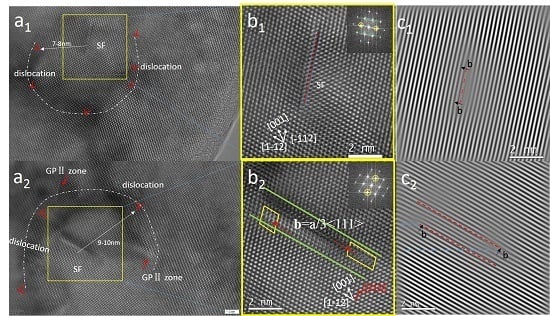
Figure 2(a1,a2) shows the high-resolution electron microscopy (HREM) images of rolled 7075 Al alloys after artificial aging at 70 °C for 75 h. In Figure 2(a1), the dislocations, marked with ‘T’, form a circle, as shown by the white dotted line. Interestingly, a stacking fault is found in the center of the circle, highlighted by the yellow frame. An enlarged image of the yellow square of Figure 2(a1) is shown in Figure 2 (b1), and the insert image shows the Fast Fourier Transformation (FFT) of Figure 2 (b1). An inserted atomic plane along the [−112] direction in the (111) plane is observed at the red spots. The insert plane (red spots), along with the two rows around it (green lines), forms a stacking fault with three layers of atoms. Moreover, emanative lines in the insert FFT spectrum could indicate the emergence of SF. Figure 2 (c1) is the Inverse Fast Fourier Transformation (IFFT) image of the (111) reflections. Every stripe represents a (111) plane, and there is an inserted (111) plane at the red dotted line, further confirming our viewpoint. Each end of the inserted plane is a Frank partial dislocation.
Similarly, in Figure 2(a2), a stacking fault with several rows of atoms emerges in the center of a circle, which has a radius of about 9–10 nm formed by precipitates and dislocations. Figure 2(b2) is the magnified picture of Figure 2(a2), in which two inserted atomic planes marked with red spots can be observed. Through Burgers circuits (made up of the yellow lines), it is confirmed that the partial dislocations in this paper are Frank partial dislocations with b = a/3<111>. Figure 2(c2), the IFFT of the (111) reflections, also clearly shows two inserted atomic planes. As the two partial dislocations are not on a straight line, the stacking fault in Figure 2(b1) is regarded as precursory, before one or both Frank partial climbs along the direction perpendicular to the (111) plane. As a result, the SF broadens to eight layers.
Figure 3a shows an HREM image with longer artificial aging (175 h). Figure 3b shows the magnified image of Figure 3a, with the insert picture as the corresponding FFT. The morphology and the diffraction patterns of the two GP II zones can be clearly observed (the arrows’ points). Interestingly, there is an intrinsic stacking fault between the two GP II zones. The atoms by the lines are well arranged, except for a little distortion (the green curve), while a layer of atoms seems to be drawn out between the lines. Similarly, the IFFT image shows that there is an absence of a (111) plane, which, in this case, is an intrinsic stacking fault.
A phenomenon worth mentioning is that the SFs nucleate around dislocations or precipitates (Figure 2 shows 7–10 nm and Figure 3 shows 2 nm). Hence, the precipitates and dislocations here are speculated to have effects on the formation of SFs.
The formation process of stacking faults will be analyzed using, as an example, an intrinsic stacking fault, the formation model of which is shown in Figure 4. The smaller red spheres are Zn atoms, while the larger blue spheres represent Al atoms. To simplify the model, only Zn atoms are taken into consideration, as the GP II zone is the aggregation of Zn atoms [15] on {111}Al. Moreover, the motion of the atoms during deformation is not considered in this paper. Figure 4a is the atomic arrangement of solid solution state along a <110> axis, and Zn distributes uniformly. Vacancies and dislocations are induced after deformation, as shown in Figure 4b. Dislocation cores act as fast paths for diffusing atoms, since the disorder in the core region effectively lowers the activation energy for diffusion [14]. Hence, Zn atoms diffuse rapidly through defects, and accumulate near the dislocation. During the aging process, vacancies migrate towards the dislocations to release the stress caused by dislocations [17]. Once the vacancies approach, Zn-vacancy clusters form and grow into GP II zones on {111}Al, and the vacancies left are usually absorbed by dislocations or grain boundaries [18]. However, in this paper, two GP II zones formed very closely (2 nm) in Figure 4c and, as a result, high strain may be produced between them. In this case, the vacancies left tended to gather together (an intrinsic stacking fault formed) to release the strain and lower the energy. In other words, two GP II zones and the SF in the middle formed a stable GP II-SF group. On one hand, the emergence of SF reduces the free energy of the system. On the other hand, the two GP regions play a role in the pinning of the SF formed by the migration and coalescence of the vacancies. This is why, in this paper, it was able to stably exist during heating, while some other SFs with Frank partial dislocations have tended to disappear during heating [10] or irradiation [11].
A stacking fault is the destruction of the normal stacking sequence of close-packed planes. For aluminum, the plane is {111}, indicating that the stacking faults in aluminum always occur in {111}. GP II zones also generate in this plane, and influence atomic arrangement, which may increase the possibility of stacking faults. This is another important reason for the GP II zones in this paper promoting SFs to emerge.
The formation of extrinsic SFs in this paper is considered to have a similar mechanism to that of intrinsic SFs. As shown in Figure 2 (a1), a large number of dislocations are produced after deformation. Interestingly, these dislocations form a radius of about 9 nm, as shown in the white line of the figure. In this case, vacancies migrate towards dislocations, since the stress field caused by dislocations readily affects vacancies [17], and stacking faults are formed as the vacancies gather. However, this kind of stacking fault is not stable, as it is not observed after aging for 175 h. This is predominantly because, under the influence of heat, the Frank partial dislocation at both ends of the fault continuously absorbs more vacancies [10], making it climb along the direction perpendicular to the (111) plane (as shown in Figure 2(b1,b2)), thus widening the stacking fault.

4. Conclusions

In summary, stabled SFs with Frank partial dislocations are found in rolled (50% reduction, with a strain rate <1 s−1) aluminum alloy after aging. Precipitates and dislocations have a great effect on the formation of the SFs, which offers a new perspective for SFs in high stacking-fault energy alloys. However, the critical conditions necessary for precipitates to influence SFs, such as how close the precipitates should be or how much strain they will produce, need to be further investigated, as not all precipitates produce SFs.

Acknowledgments

This work was financially supported by National Key Technology R&D Program of China (2015BAG20B04 and 2015BAF06B01-3), the National Key Research and Development Program of China (2016YFC0801903 and 2016YFF0203301) and National Natural Science Foundation of China (No. 51175023 and No. U1537212).

Author Contributions

Sijie Li and Hongyun Luo conceived and designed the experiments; Sijie Li performed the experiments; Sijie Li, Hongyun Luo and Hui Wang analyzed the data; Pingwei Xu, Jun Luo, Chu Liu and Tao Zhang contributed materials and analysis tools; Sijie Li wrote the paper.

Conflicts of Interest

The authors declare no conflict of interest.

References

  1. Liao, X.Z.; Zhou, F.; Lavernia, E.J.; He, D.W.; Zhu, Y.T. Deformation twins in nanocrystalline Al. Appl. Phys. Lett. 2003, 83, 5062–5064. [Google Scholar] [CrossRef]
  2. Yamakov, V.; Wolf, D.; Phillpot, S.R.; Gleiter, H. Deformation twinning in nanocrystalline Al by molecular dynamics simulation. Acta Mater. 2002, 50, 5005–5020. [Google Scholar] [CrossRef]
  3. Jin, S.B.; Zhang, K.; Bjorge, R.; Tao, N.R.; Marthinsen, K.; Lu, K.; Li, Y.J. Formation of incoherent deformation twin boundaries in a coarse-grained Al-7Mg alloy. Appl. Phys. Lett. 2015, 107, 091901. [Google Scholar] [CrossRef]
  4. Cao, B.; Daphalapurkar, N.P.; Ramesh, K.T. Ultra-high-strain-rate shearing and deformation twinning in nanocrystalline aluminum. Meccanica 2015, 50, 561–574. [Google Scholar] [CrossRef]
  5. Li, B.Q.; Sui, M.L.; Li, B.; Ma, E.; Mao, S.X. Reversible Twinning in Pure Aluminum. Phys. Rev. Lett. 2009, 102, 205504. [Google Scholar] [CrossRef] [PubMed]
  6. Han, W.Z.; Cheng, G.M.; Li, S.X.; Wu, S.D.; Zhang, Z.F. Deformation induced microtwins and stacking faults in aluminum single crystal. Phys. Rev. Lett. 2008, 101, 115505. [Google Scholar] [CrossRef] [PubMed]
  7. Zhao, F.; Wang, L.; Fan, D.; Bie, B.X.; Zhou, X.M.; Suo, T.; Li, Y.L.; Chen, M.W.; Liu, C.L.; Qi, M.L.; et al. Macrodeformation Twins in Single-Crystal Aluminum. Phys. Rev. Lett. 2016, 116. [Google Scholar] [CrossRef] [PubMed]
  8. Wang, Y.B.; Sui, M.L. Atomic-scale in situ observation of lattice dislocations passing through twin boundaries. Appl. Phys. Lett. 2009, 94, 021909. [Google Scholar] [CrossRef]
  9. Liao, X.Z.; Zhou, F.; Lavernia, E.J.; Srinivasan, S.G.; Baskes, M.I.; He, D.W.; Zhu, Y.T. Deformation mechanism in nanocrystalline Al: Partial dislocation slip. Appl. Phys. Lett. 2003, 83, 632–634. [Google Scholar] [CrossRef]
  10. Wu, X.L.; Li, B.; Ma, E. Vacancy clusters in ultrafine grained Al by severe plastic deformation. Appl. Phys. Lett. 2007, 91, 141908. [Google Scholar] [CrossRef]
  11. Yang, W.; Dong, R.; Jiang, L.; Wu, G.; Hussain, M. Unstable stacking faults in submicron/micron Al grammins in multi-SiCp/multi-Al nanocomposite. Vacuum 2015, 122, 1–5. [Google Scholar] [CrossRef]
  12. Monnet, G. New insights into radiation hardening in face-centered cubic alloys. Scr. Mater. 2015, 100, 24–27. [Google Scholar] [CrossRef]
  13. Zheng, Y.; Luo, B.; Bai, Z.; Wang, J.; Yin, Y. Study of the Precipitation Hardening Behaviour and Intergranular Corrosion of Al-Mg-Si Alloys with Differing Si Contents. Metals 2017, 7, 387. [Google Scholar] [CrossRef]
  14. Hu, T.; Ma, K.; Topping, T.D.; Schoenung, J.M.; Lavernia, E.J. Precipitation phenomena in an ultrafine-grained Al alloy. Acta Mater. 2013, 61, 2163–2178. [Google Scholar] [CrossRef]
  15. Berg, L.K.; Gjonnes, J.; Hansen, V.; Li, X.Z.; Knutson-Wedel, M.; Waterloo, G.; Schryvers, D.; Wallenberg, L.R. GP-zones in Al-Zn-Mg alloys and their role in artificial aging. Acta Mater. 2001, 49, 3443–3451. [Google Scholar] [CrossRef]
  16. Xu, P.; Luo, H. Improving the ductility of nanostructured Al alloy using strongly textured nano-laminated structure combined with nano-precipitates. Mater. Sci. Eng. A Struct. 2016, 675, 323–337. [Google Scholar] [CrossRef]
  17. Sha, G.; Cerezo, A. Early-stage precipitation in Al-Zn-Mg-Cu alloy (7050). Acta Mater. 2004, 52, 4503–4516. [Google Scholar] [CrossRef]
  18. Kelly, A.; Nicholson, R.B. Precipitation hardening. Prog. Mater. Sci. 1963, 10, 151–391. [Google Scholar]
Figure 1. XRD patterns of the aluminum alloy before (SST) and after deformation treatment (50%), as well as the one after aging for 175 h (50%-175 h).
Crystals 07 00375 g001
Figure 2. HREM images of rolled 7075 Al alloys after aging at 70 °C for 75 h; (a1,a2) HREM images of stacking faults surrounded by dislocations and GP II zones; (b1,b2) the magnified pictures of the square in (a1,a2) show inserted atomic planes along [−112] direction; (c1,c2) IFFT images of (111) patterns show inserted (111) planes.
Crystals 07 00375 g002
Figure 3. HREM images of rolled 7075 Al alloys after aging at 70 °C for 175 h: (a) HREM image; (b) the magnified picture of the yellow square in (a) shows an intrinsic stacking fault between two GP II zones; (c) IFFT shows one drawn-out (111) plane.
Crystals 07 00375 g003
Figure 4. A schematic image showing the formation process of an intrinsic stacking fault: (a) atomic arrangement of solid solution state; (b) vacancies and dislocations induced by deformation; (c) a stacking fault emerges between two precipitates during aging through vacancies gathering to lower the energy.
Crystals 07 00375 g004